all SUZUKI SWIFT 2008 2.G Service Workshop Manual
[x] Cancel search | Manufacturer: SUZUKI, Model Year: 2008, Model line: SWIFT, Model: SUZUKI SWIFT 2008 2.GPages: 1496, PDF Size: 34.44 MB
Page 393 of 1496
Downloaded from www.Manualslib.com manuals search engine Ignition System: 1H-1
Engine
Ignition System
General Description
Ignition System ConstructionS7RS0B1801001
The ignition system is an electronic (distributorless) ignition system. It consists of the parts as described below.
• ECM
It detects the engine and vehicle conditions through the si gnals from the sensors, determines the most suitable
ignition timing and time for electricity to flow to the primar y coil and sends a signal to the ignitor (power unit) in the
ignition coil assembly.
• Ignition coil assembly (including an ignitor)
The ignition coil assembly has a built -in ignitor which turns ON and OFF the current flow to the primary coil
according to the signal from ECM. When the current flow to the primary coil is turned OFF, a high voltage is induced
in the secondary coil.
• High-tension cords and spark plugs
• CMP sensor (Camshaft position sensor) and CKP sensor (Crankshaft position sensor)
Using signals from these sensors, ECM identifies the specific cylinder whose piston is in the compression stroke,
detects the crank angle and adjusts in itial ignition timing automatically.
• TP sensor, ECT sensor, MAP sensor, MAF sensor, IAT sensor, knock sensor and other sensors / switches
Although this ignition system does not have a distributor, it has two ignition coil assemblies (one is for No.1 and No.4
spark plugs and the other is for No.2 and No.3 spark plugs). W hen an ignition signal is sent from ECM to the ignitor in
the ignition coil assembly for No.1 and No.4 spark plugs, a high voltage is induced in the secondary coil and that
passes through the high-tension cords and causes No.1 and No.4 spark plugs to spark simultaneously. Likewise,
when an ignition signal is sent to the ignitor in the ot her ignition coil assembly, No.2 and No.3 spark plugs spark
simultaneously.
Page 395 of 1496
Downloaded from www.Manualslib.com manuals search engine Ignition System: 1H-3
Component Location
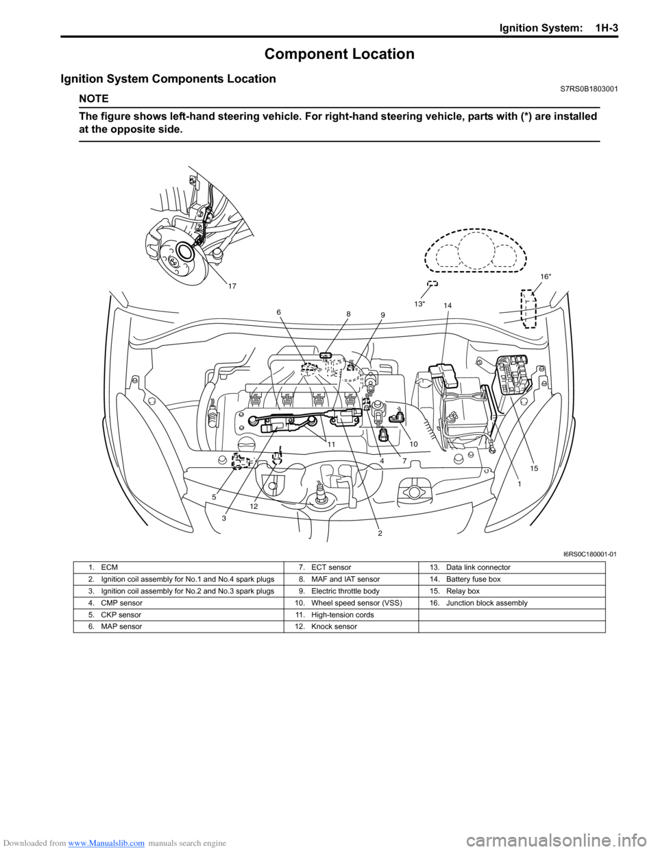
Ignition System Components LocationS7RS0B1803001
NOTE
The figure shows left-hand steering vehicle. For right-hand steering vehicle, parts with (*) are installed
at the opposite side.
16*
1
2
14
7
5 12 11
410
6
89
3 13*
15
17
I6RS0C180001-01
1. ECM 7. ECT sensor13. Data link connector
2. Ignition coil assembly for No.1 and No.4 spark plugs 8. MAF and IAT sensor 14. Battery fuse box
3. Ignition coil assembly for No.2 and No.3 spark plugs 9. Electric throttle body 15. Relay box
4. CMP sensor 10. Wheel speed sensor (VSS) 16. Junction block assembly
5. CKP sensor 11. High-tension cords
6. MAP sensor 12. Knock sensor
Page 396 of 1496
Downloaded from www.Manualslib.com manuals search engine 1H-4 Ignition System:
Diagnostic Information and Procedures
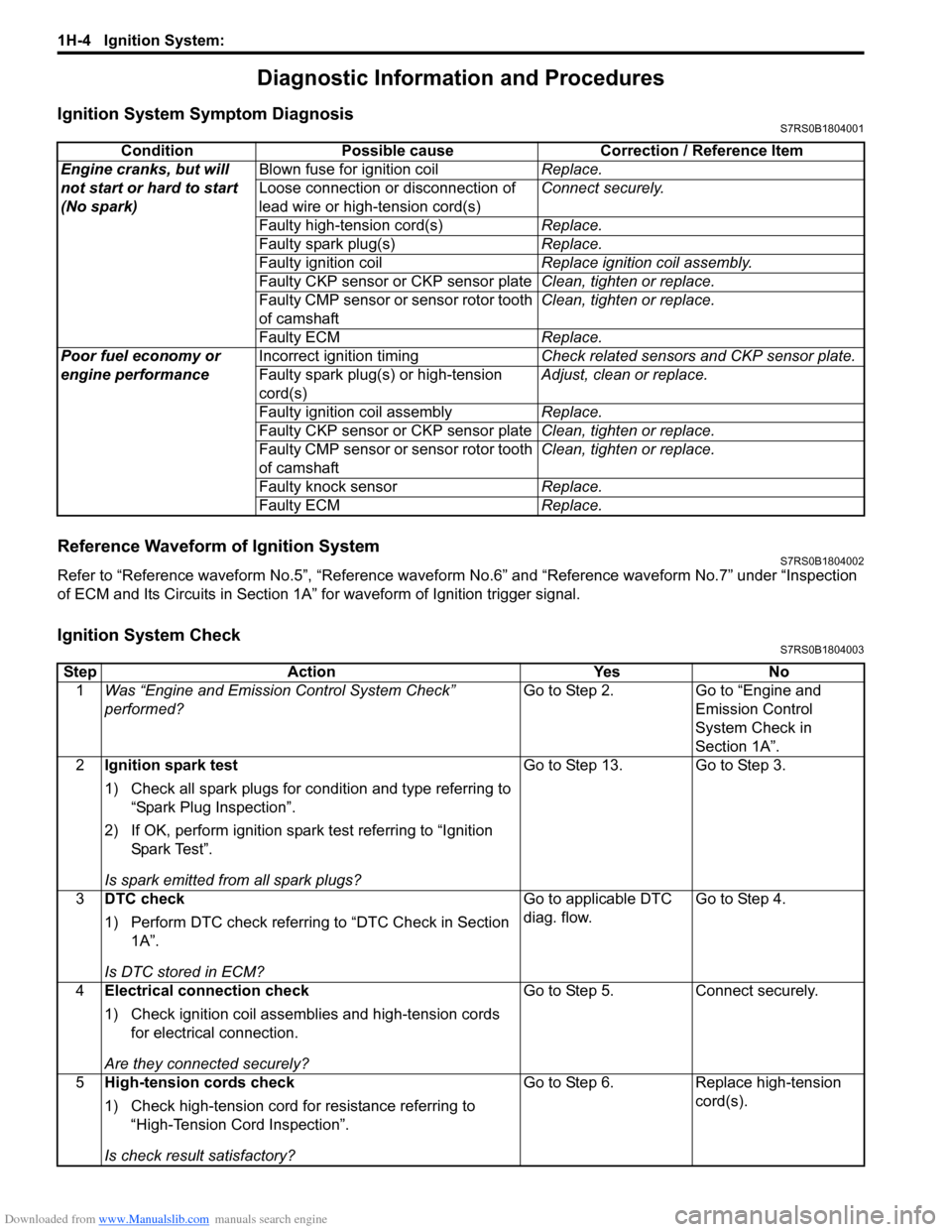
Ignition System Symptom DiagnosisS7RS0B1804001
Reference Waveform of Ignition SystemS7RS0B1804002
Refer to “Reference waveform No.5”, “Reference waveform No.6” and “Reference waveform No.7” under “Inspection
of ECM and Its Circuits in Section 1A” for waveform of Ignition trigger signal.
Ignition System CheckS7RS0B1804003
Condition Possible cause Correction / Reference Item
Engine cranks, but will
not start or hard to start
(No spark) Blown fuse for ignition coil
Replace.
Loose connection or disconnection of
lead wire or high-tension cord(s) Connect securely.
Faulty high-tension cord(s) Replace.
Faulty spark plug(s) Replace.
Faulty ignition coil Replace ignition coil assembly.
Faulty CKP sensor or CKP sensor plate Clean, tighten or replace.
Faulty CMP sensor or sensor rotor tooth
of camshaft Clean, tighten or replace.
Faulty ECM Replace.
Poor fuel economy or
engine performance Incorrect ignition timing
Check related sensors and CKP sensor plate.
Faulty spark plug(s) or high-tension
cord(s) Adjust, clean or replace.
Faulty ignition coil assembly Replace.
Faulty CKP sensor or CKP sensor plate Clean, tighten or replace.
Faulty CMP sensor or sensor rotor tooth
of camshaft Clean, tighten or replace.
Faulty knock sensor Replace.
Faulty ECM Replace.
StepAction YesNo
1 Was “Engine and Emission Control System Check”
performed? Go to Step 2.
Go to “Engine and
Emission Control
System Check in
Section 1A”.
2 Ignition spark test
1) Check all spark plugs for condition and type referring to
“Spark Plug Inspection”.
2) If OK, perform ignition spark test referring to “Ignition Spar k Tes t”.
Is spark emitted from all spark plugs? Go to Step 13. Go to Step 3.
3 DTC check
1) Perform DTC check referring to “DTC Check in Section
1A”.
Is DTC stored in ECM? Go to applicable DTC
diag. flow.
Go to Step 4.
4 Electrical connection check
1) Check ignition coil assemblies and high-tension cords
for electrical connection.
Are they connected securely? Go to Step 5.
Connect securely.
5 High-tension cords check
1) Check high-tension cord for resistance referring to
“High-Tension Cord Inspection”.
Is check result satisfactory? Go to Step 6.
Replace high-tension
cord(s).
Page 398 of 1496
Downloaded from www.Manualslib.com manuals search engine 1H-6 Ignition System:
Ignition Spark TestS7RS0B1804004
1) Remove air cleaner assembly with air intake pipe.
2) Disconnect all injector couplers from injectors.
WARNING!
Without disconnection of injector couplers,
combustible gas may come out from spark
plug holes during this test and may get
ignited in engine room.
3) Remove spark plug and check it for condition and
type referring to “Spark Plug Inspection”.
4) If OK, connect ignition coil coupler to ignition coil assembly and connect spark plug to ignition coil
assembly or high-tension cord. Ground spark plug. 5) Crank engine and check if each spark plug sparks.
6) If no spark is emitted, inspect the related parts as
described in “Ignition System Symptom Diagnosis”.
Repair Instructions
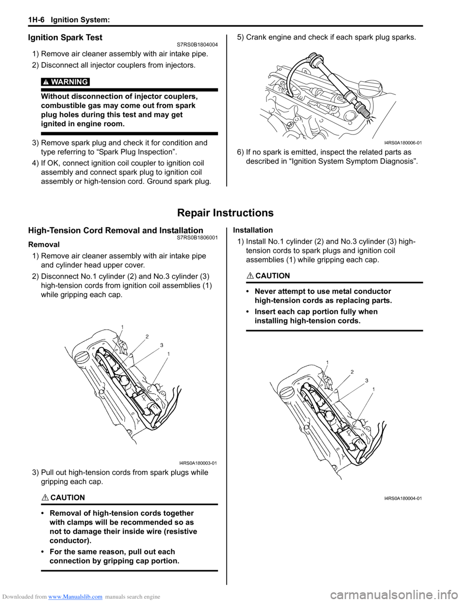
High-Tension Cord Removal and InstallationS7RS0B1806001
Removal
1) Remove air cleaner assembly with air intake pipe and cylinder head upper cover.
2) Disconnect No.1 cylinder (2) and No.3 cylinder (3)
high-tension cords from ignition coil assemblies (1)
while gripping each cap.
3) Pull out high-tension cords from spark plugs while gripping each cap.
CAUTION!
• Removal of high-tension cords together with clamps will be recommended so as
not to damage their inside wire (resistive
conductor).
• For the same reason, pull out each connection by gripping cap portion.
Installation
1) Install No.1 cylinder (2) and No.3 cylinder (3) high-
tension cords to spark plugs and ignition coil
assemblies (1) while gripping each cap.
CAUTION!
• Never attempt to use metal conductor high-tension cords as replacing parts.
• Insert each cap portion fully when installing high-tension cords.
I4RS0A180006-01
I4RS0A180003-01
I4RS0A180004-01
Page 399 of 1496
Downloaded from www.Manualslib.com manuals search engine Ignition System: 1H-7
High-Tension Cord InspectionS7RS0B1806002
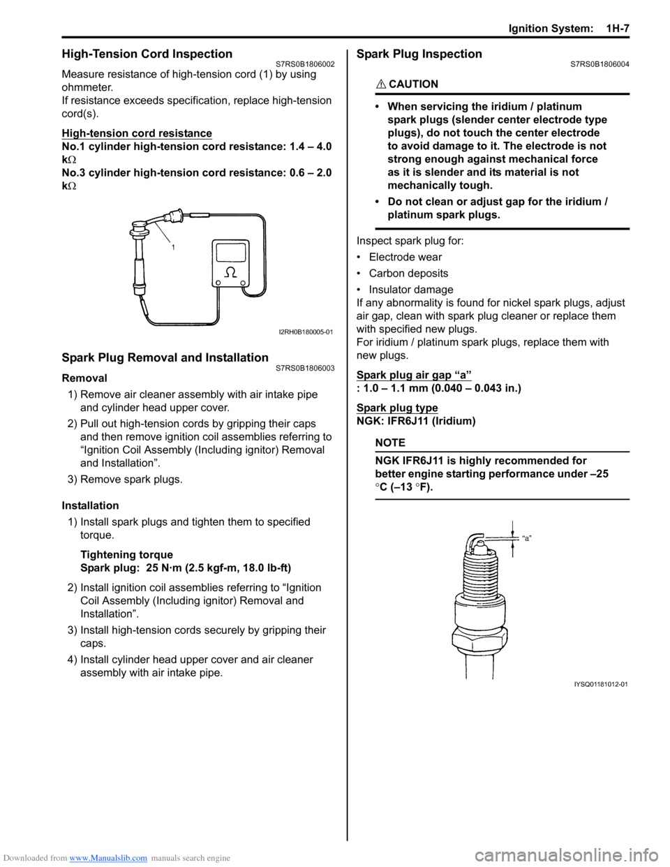
Measure resistance of high-tension cord (1) by using
ohmmeter.
If resistance exceeds specification, replace high-tension
cord(s).
High-tension cord resistance
No.1 cylinder high-tension cord resistance: 1.4 – 4.0
k Ω
No.3 cylinder high-tension cord resistance: 0.6 – 2.0
k Ω
Spark Plug Removal and InstallationS7RS0B1806003
Removal
1) Remove air cleaner assembly with air intake pipe and cylinder head upper cover.
2) Pull out high-tension cords by gripping their caps and then remove ignition coil assemblies referring to
“Ignition Coil Assembly (Inc luding ignitor) Removal
and Installation”.
3) Remove spark plugs.
Installation 1) Install spark plugs and tighten them to specified torque.
Tightening torque
Spark plug: 25 N·m (2.5 kgf-m, 18.0 lb-ft)
2) Install ignition coil assemblies referring to “Ignition Coil Assembly (Including ignitor) Removal and
Installation”.
3) Install high-tension cords securely by gripping their caps.
4) Install cylinder head upper cover and air cleaner assembly with air intake pipe.
Spark Plug InspectionS7RS0B1806004
CAUTION!
• When servicing the iridium / platinum
spark plugs (slender center electrode type
plugs), do not touch the center electrode
to avoid damage to it. The electrode is not
strong enough against mechanical force
as it is slender and its material is not
mechanically tough.
• Do not clean or adjust gap for the iridium / platinum spark plugs.
Inspect spark plug for:
• Electrode wear
• Carbon deposits
• Insulator damage
If any abnormality is found for nickel spark plugs, adjust
air gap, clean with spark plug cleaner or replace them
with specified new plugs.
For iridium / platinum spark plugs, replace them with
new plugs.
Spark plug air gap
“a”
: 1.0 – 1.1 mm (0.040 – 0.043 in.)
Spark plug type
NGK: IFR6J11 (Iridium)
NOTE
NGK IFR6J11 is highly recommended for
better engine starting performance under –25
°C (–13 °F).
I2RH0B180005-01
IYSQ01181012-01
Page 400 of 1496
Downloaded from www.Manualslib.com manuals search engine 1H-8 Ignition System:
Ignition Coil Assembly (Including ignitor)
Removal and Installation
S7RS0B1806005
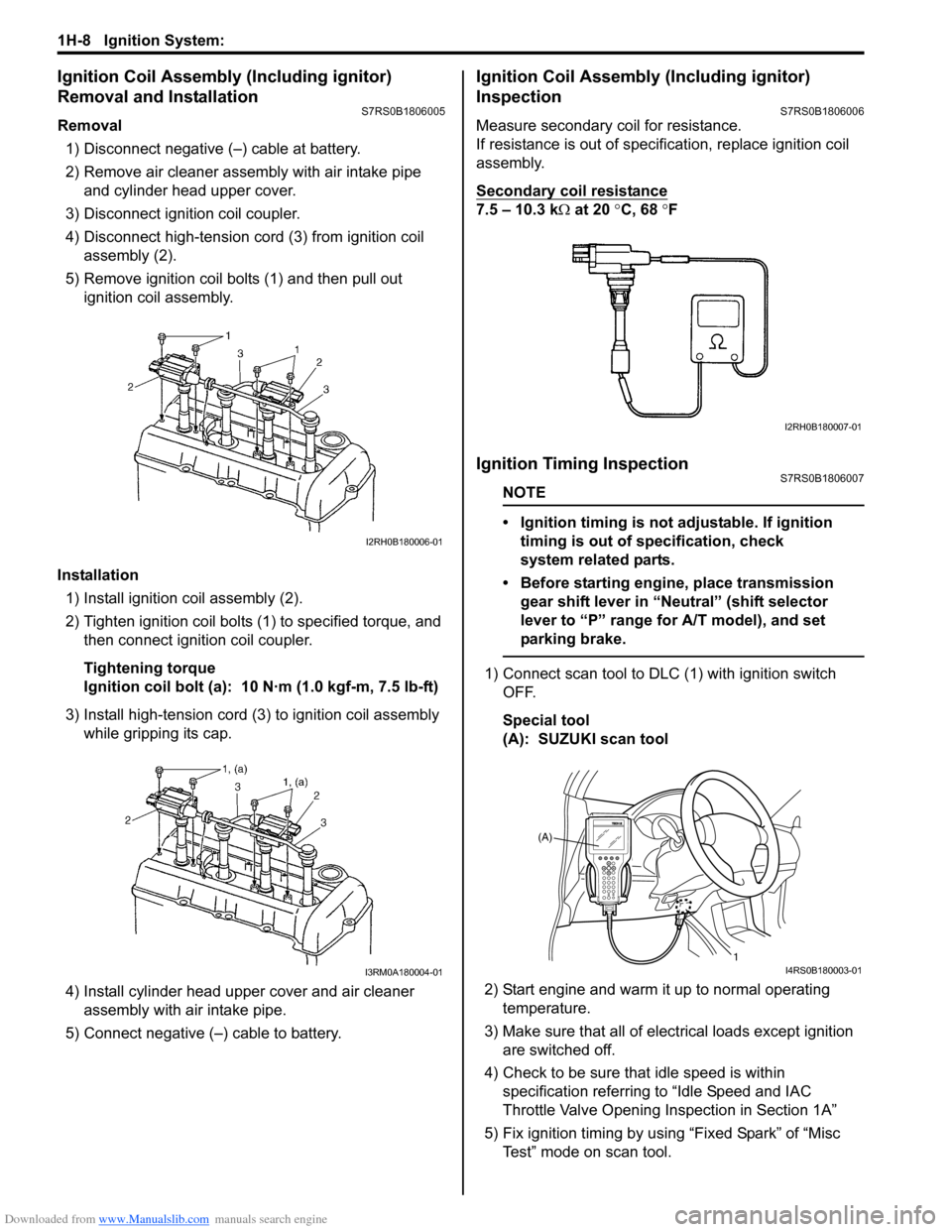
Removal1) Disconnect negative (–) cable at battery.
2) Remove air cleaner assembly with air intake pipe and cylinder head upper cover.
3) Disconnect ignition coil coupler.
4) Disconnect high-tension cord (3) from ignition coil assembly (2).
5) Remove ignition coil bolts (1) and then pull out ignition coil assembly.
Installation 1) Install ignition coil assembly (2).
2) Tighten ignition coil bolts (1) to specified torque, and then connect igni tion coil coupler.
Tightening torque
Ignition coil bolt (a): 10 N·m (1.0 kgf-m, 7.5 lb-ft)
3) Install high-tension cord (3) to ignition coil assembly while gripping its cap.
4) Install cylinder head upper cover and air cleaner assembly with air intake pipe.
5) Connect negative (–) cable to battery.
Ignition Coil Assembly (Including ignitor)
Inspection
S7RS0B1806006
Measure secondary coil for resistance.
If resistance is out of specification, replace ignition coil
assembly.
Secondary coil resistance
7.5 – 10.3 k Ω at 20 °C, 68 ° F
Ignition Timing InspectionS7RS0B1806007
NOTE
• Ignition timing is not adjustable. If ignition
timing is out of specification, check
system related parts.
• Before starting engine, place transmission gear shift lever in “Neutral” (shift selector
lever to “P” range for A/T model), and set
parking brake.
1) Connect scan tool to DLC (1) with ignition switch OFF.
Special tool
(A): SUZUKI scan tool
2) Start engine and warm it up to normal operating temperature.
3) Make sure that all of electrical loads except ignition are switched off.
4) Check to be sure that idle speed is within specification referring to “Idle Speed and IAC
Throttle Valve Opening Inspection in Section 1A”
5) Fix ignition timing by using “Fixed Spark” of “Misc Test” mode on scan tool.
I2RH0B180006-01
I3RM0A180004-01
I2RH0B180007-01
(A)
1
I4RS0B180003-01
Page 401 of 1496
Downloaded from www.Manualslib.com manuals search engine Ignition System: 1H-9
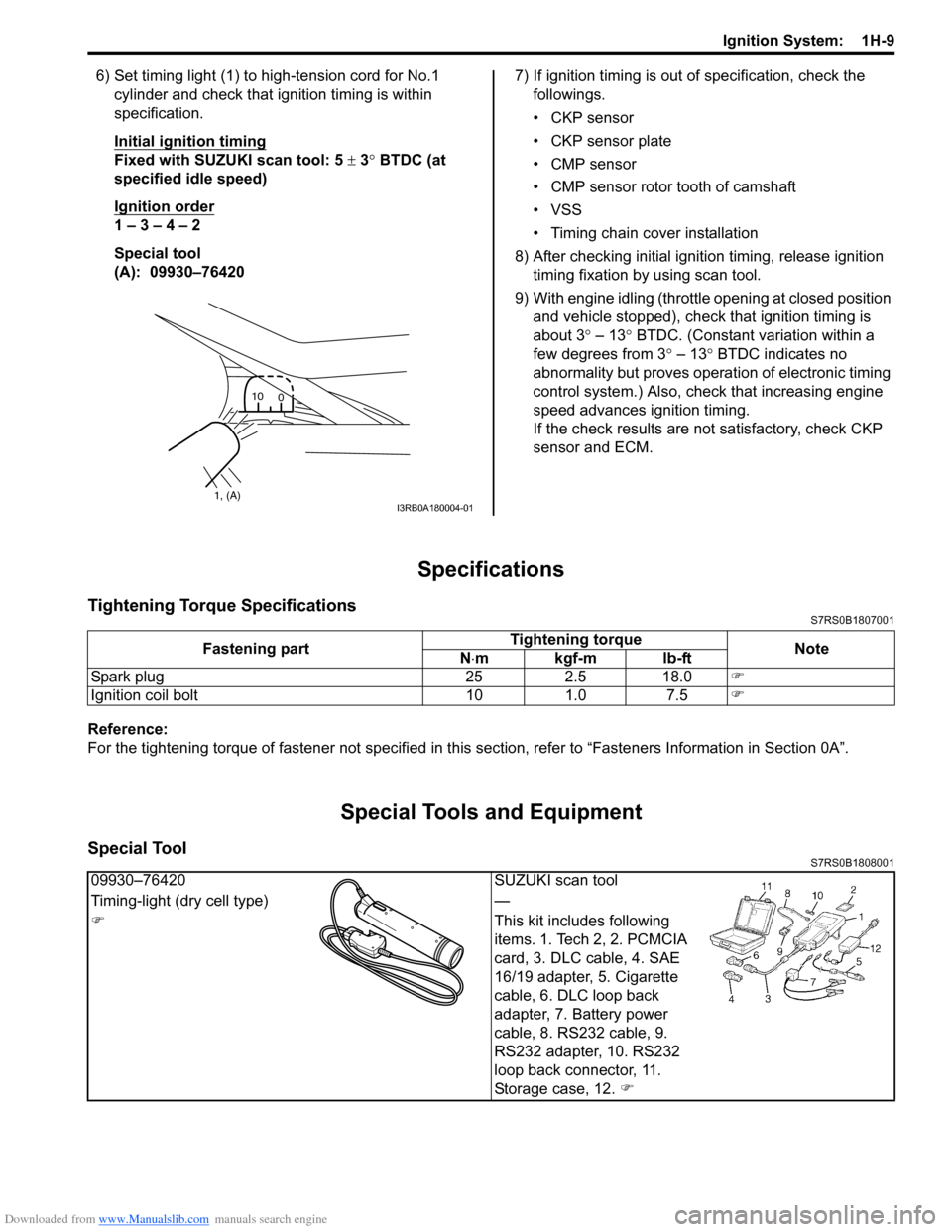
6) Set timing light (1) to high-tension cord for No.1 cylinder and check that ignition timing is within
specification.
Initial ignition timing
Fixed with SUZUKI scan tool: 5 ± 3° BTDC (at
specified idle speed)
Ignition order
1 – 3 – 4 – 2
Special tool
(A): 09930–76420 7) If ignition timing is out
of specification, check the
followings.
• CKP sensor
• CKP sensor plate
• CMP sensor
• CMP sensor rotor tooth of camshaft
• VSS
• Timing chain cover installation
8) After checking initial igniti on timing, release ignition
timing fixation by using scan tool.
9) With engine idling (throttl e opening at closed position
and vehicle stopped), check that ignition timing is
about 3 ° – 13° BTDC. (Constant variation within a
few degrees from 3 ° – 13° BTDC indicates no
abnormality but proves operation of electronic timing
control system.) Also, check that increasing engine
speed advances ignition timing.
If the check results are not satisfactory, check CKP
sensor and ECM.
Specifications
Tightening Torque SpecificationsS7RS0B1807001
Reference:
For the tightening torque of fastener not specified in this section, refer to “Fasteners Information in Section 0A”.
Special Tools and Equipment
Special ToolS7RS0B1808001
1, (A)10
0I3RB0A180004-01
Fastening part Tightening torque
Note
N ⋅mkgf-mlb-ft
Spark plug 25 2.5 18.0 )
Ignition coil bolt 10 1.0 7.5 )
09930–76420SUZUKI scan tool
Timing-light (dry cell type) —
) This kit includes following
items. 1. Tech 2, 2. PCMCIA
card, 3. DLC cable, 4. SAE
16/19 adapter, 5. Cigarette
cable, 6. DLC loop back
adapter, 7. Battery power
cable, 8. RS232 cable, 9.
RS232 adapter, 10. RS232
loop back connector, 11.
Storage case, 12. )
Page 403 of 1496
Downloaded from www.Manualslib.com manuals search engine Starting System: 1I-2
ConditionPossible cause Correction / Reference Item
Motor not running (No
operating sound of
magnetic switch) Shift lever switch is not in P or N, or not
adjusted (A/T)
Shift in P or N, or
adjust switch. (A/T)
Battery run down Recharge battery.
Battery voltage too low due to battery
deterioration Replace battery.
Poor contact in battery terminal
connection Retighten or replace.
Loose grounding cable connection Retighten.
Fuse set loose or blown off Tighten or replace.
Poor contacting action of ignition switch
and magnetic switch Replace.
Lead wire coupler loose in place Retighten.
Open-circuit between ignition switch and
magnetic switch Repair.
Open-circuit in pull-in coil Replace magnetic switch.
Brushes are seating poorly or worn
down Repair or replace.
Poor sliding of plunger and/or pinion Repair.
Faulty starting motor control relay “Main Relay, Fuel Pump Relay and Starting
Motor Control Relay Inspection in Section 1C”.
Faulty ECM and its circuit “Inspection of ECM and Its Circuits in Section
1A”.
Motor not running
(Operating sound of
magnetic switch heard) Battery run down
Recharge battery.
Battery voltage too low due to battery
deterioration Replace battery.
Loose battery cable connections Retighten.
Burnt main contact point, or poor
contacting action of magnetic switch Replace magnetic switch.
Brushes are seating poorly or worn
down Repair or replace.
Weakened brush spring Replace.
Burnt commutator Replace armature.
Layer short-circuit of armature Replace.
Crankshaft rotation obstructed Repair.
Starting motor running
but too slow (small
torque) (If battery and
wiring are satisfactory,
inspect starting motor) Insufficient contact
of magnetic switch
main contacts Replace magnetic switch.
Layer short-circuit of armature Replace.
Disconnected, burnt or worn
commutator Repair commutator or replace armature.
Worn brushes Replace brush.
Weakened brush springs Replace spring.
Burnt or abnormally worn end bush Replace bush.
Starting motor running,
but not cranking engine Worn pinion tip
Replace over-running clutch.
Poor sliding of over-running clutch Repair.
Over-running clutch slipping Replace over-running clutch.
Worn teeth of ring gear Replace flywheel (M/T) or drive plate (A/T).
Noise Abnormally worn bush Replace bush.
Worn pinion or worn teeth of ring gear Replace over-running clutch, flywheel (M/T) or
drive plate (A/T).
Poor sliding of pinion (failure in return
movement) Repair or replace.
Worn internal or planetary gear teeth Replace.
Lack of oil in each part Lubricate.
Starting motor does not
stop running Fused contact points of magnetic switch
Replace magnetic switch.
Short-circuit between turns of magnetic
switch coil (layer short-circuit) Replace magnetic switch.
Failure of returning action in ignition
switch Replace.
Page 406 of 1496
Downloaded from www.Manualslib.com manuals search engine 1I-5 Starting System:
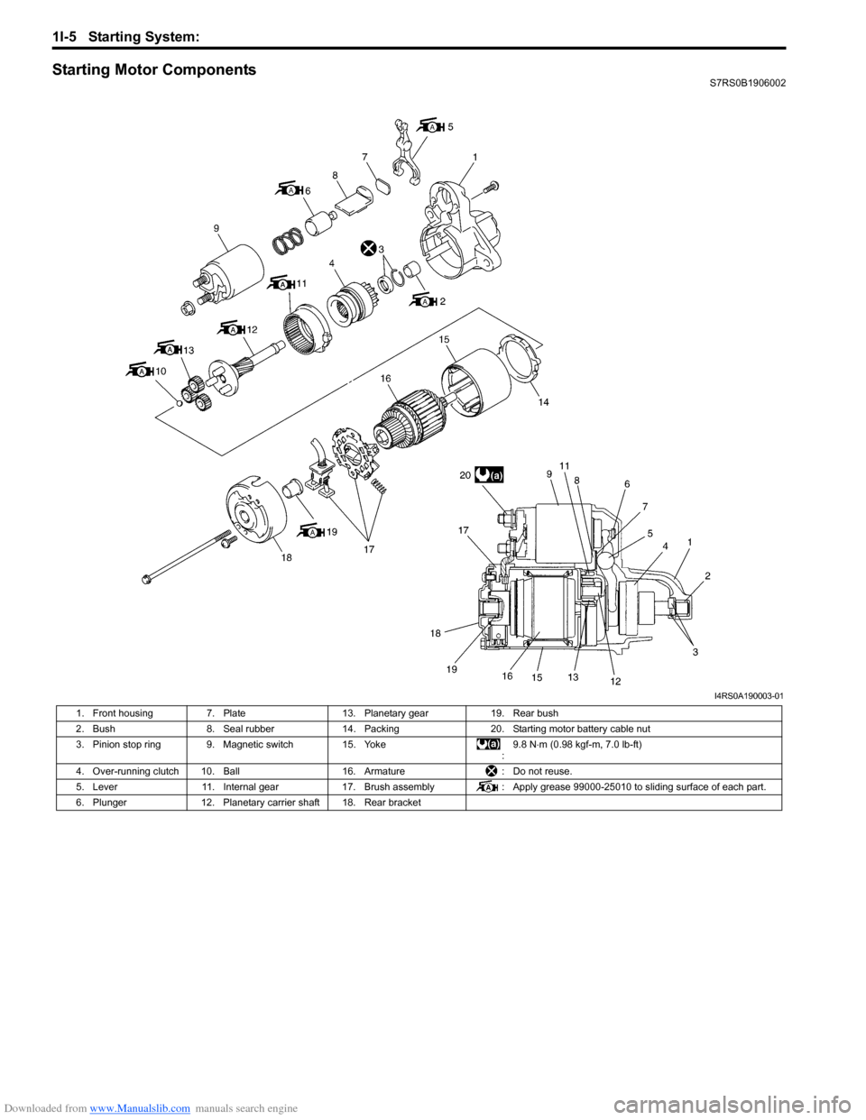
Starting Motor ComponentsS7RS0B1906002
I4RS0A190003-01
1. Front housing 7. Plate 13. Planetary gear 19. Rear bush
2. Bush 8. Seal rubber 14. Packing 20. Starting motor battery cable nut
3. Pinion stop ring 9. Magnetic switch 15. Yoke :9.8 N
⋅m (0.98 kgf-m, 7.0 lb-ft)
4. Over-running clutch 10. Ball 16. Armature: Do not reuse.
5. Lever 11. Internal gear 17. Brush assembly : Apply grease 99000-25010 to sliding surface of each part.
6. Plunger 12. Planetary carrier shaft 18. Rear bracket
Page 407 of 1496
Downloaded from www.Manualslib.com manuals search engine Starting System: 1I-6
Starting Motor InspectionS7RS0B1906003
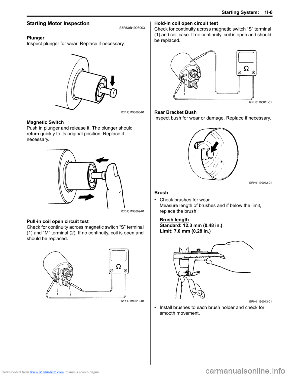
Plunger
Inspect plunger for wear. Replace if necessary.
Magnetic Switch
Push in plunger and release it. The plunger should
return quickly to its original position. Replace if
necessary.
Pull-in coil open circuit test
Check for continuity across magnetic switch “S” terminal
(1) and “M” terminal (2). If no continuity, coil is open and
should be replaced. Hold-in coil open circuit test
Check for continuity across ma
gnetic switch “S” terminal
(1) and coil case. If no continuity, coil is open and should
be replaced.
Rear Bracket Bush
Inspect bush for wear or damage. Replace if necessary.
Brush
• Check brushes for wear. Measure length of brushes and if below the limit,
replace the brush.
Brush length
Standard: 12.3 mm (0.48 in.)
Limit: 7.0 mm (0.28 in.)
• Install brushes to each brush holder and check for smooth movement.
I2RH01190008-01
I2RH01190009-01
I2RH01190010-01
I2RH01190011-01
I2RH01190012-01
I2RH01190013-01