troubleshooting SUZUKI SWIFT 2008 2.G Service Workshop Manual
[x] Cancel search | Manufacturer: SUZUKI, Model Year: 2008, Model line: SWIFT, Model: SUZUKI SWIFT 2008 2.GPages: 1496, PDF Size: 34.44 MB
Page 1119 of 1496
Downloaded from www.Manualslib.com manuals search engine Air Bag System: 8B-81
DTC Troubleshooting
NOTE
Upon completion of inspection and repair work, perform the following items.
• Reconnect all air bag system components and ensure all components are properly mounted.
• Clear DTCs referring to “DTC Clearance”, if any.
• Repeat “Air Bag Diagnostic System Check” to confirm that the trouble has been corrected.
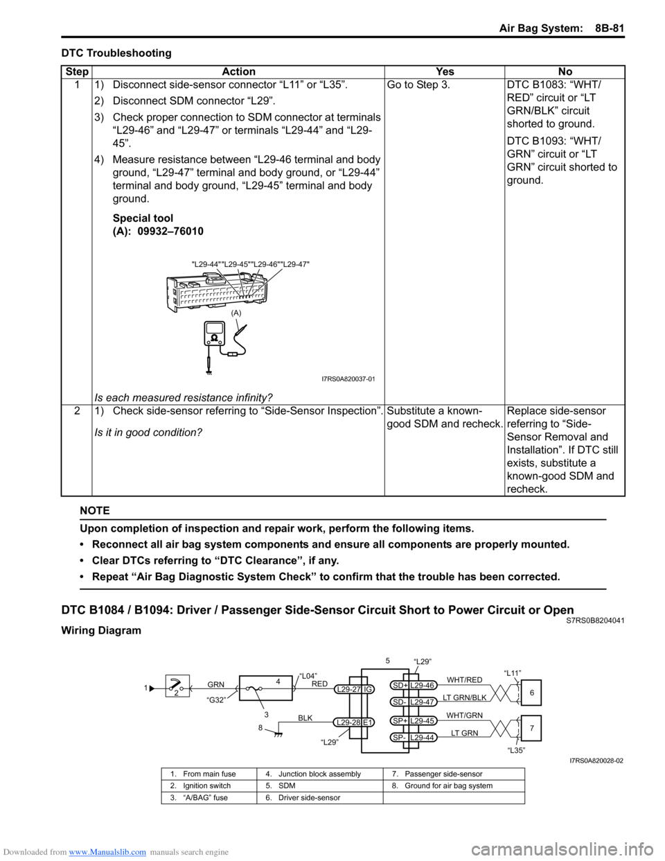
DTC B1084 / B1094: Driver / Passenger Side-Sensor Circuit Short to Power Circuit or OpenS7RS0B8204041
Wiring DiagramStep Action Yes No
1 1) Disconnect side-sensor connector “L11” or “L35”.
2) Disconnect SDM connector “L29”.
3) Check proper connection to SDM connector at terminals “L29-46” and “L29-47” or terminals “L29-44” and “L29-
45”.
4) Measure resistance between “L29-46 terminal and body ground, “L29-47” terminal and body ground, or “L29-44”
terminal and body ground, “L29-45” terminal and body
ground.
Special tool
(A): 09932–76010
Is each measured resistance infinity? Go to Step 3. DTC B1083: “WHT/
RED” circuit or “LT
GRN/BLK” circuit
shorted to ground.
DTC B1093: “WHT/
GRN” circuit or “LT
GRN” circuit shorted to
ground.
2 1) Check side-sensor referring to “Side-Sensor Inspection”. Is it in good condition? Substitute a known-
good SDM and recheck.
Replace side-sensor
referring to “Side-
Sensor Removal and
Installation”. If DTC still
exists, substitute a
known-good SDM and
recheck.
"L29-45""L29-46""L29-47"
"L29-44"
(A)
I7RS0A820037-01
12
3
GRN
RED
8
BLK
L29-27
L29-28 IG
E1
4
“L29”
“L04”
“G32”
“L29”5
WHT/RED
LT GRN/BLKL29-46
SD+
L29-47
SD-6
“L11”
WHT/GRN
LT GRNL29-45
SP+
L29-44
SP-7
“L35”
I7RS0A820028-02
1. From main fuse 4. Junction blo ck assembly 7. Passenger side-sensor
2. Ignition switch 5. SDM 8. Ground for air bag system
3. “A/BAG” fuse 6. Driver side-sensor
Page 1120 of 1496
Downloaded from www.Manualslib.com manuals search engine 8B-82 Air Bag System:
CAUTION!
• Be sure to perform “Air Bag Diagnostic System Check” before starting diagnosis according to flow.
• When measurement of resistance or voltage is required in this flow, use a tester along with a correct terminal adapter from special tool (Connector test adapter kit).
• When a check for proper connection is required, refer to “Inspection of Intermittent and Poor Connections”.
• If there is open circuit in the air bag wire harnes s, connector or terminal is found damaged, replace
the wire harness, connector and terminal as an assembly.
DTC Will Set when
The resistance measured between side-sensor circuit and power source circuit is below a specified value for specified
time.
Flow Test Description
Step 1: Check for open circuit in side-sensor circuit.
Step 2: Check for short circuit between side-sensor circuit and power supply circuit.
Step 3: Check if malfunction is in side-sensor.
DTC Troubleshooting
Step Action YesNo
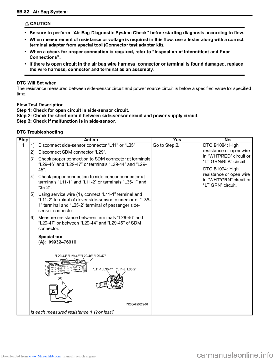
1 1) Disconnect side-sensor connector “L11” or “L35”.
2) Disconnect SDM connector “L29”.
3) Check proper connection to SDM connector at terminals “L29-46” and “L29-47” or terminals “L29-44” and “L29-
45”.
4) Check proper connection to side-sensor connector at terminals “L11-1” and “L11-2” or terminals “L35-1” and
“35-2”.
5) Using service wire (1), connect “L11-1” terminal and “L11-2” terminal of driver side-sensor connector or “L35-
1” terminal and “L35-2” terminal of passenger side-
sensor connector.
6) Measure resistance between terminals “L29-46” and “L29-47” or between “L29-44” and “L29-45” of SDM
connector.
Special tool
(A): 09932–76010
Is each measured resistance 1
Ω or less? Go to Step 2. DTC B1084: High
resistance or open wire
in “WHT/RED” circuit or
“LT GRN/BLK” circuit.
DTC B1094: High
resistance or open wire
in “WHT/GRN” circuit or
“LT GRN” circuit.
(A)
"L11-1, L35-1" "L11-2, L35-2"1
"L29-45" "L29-46" "L29-47"
"L29-44"
I7RS0A820029-01
Page 1121 of 1496
Downloaded from www.Manualslib.com manuals search engine Air Bag System: 8B-83
NOTE
Upon completion of inspection and repair work, perform the following items.
• Reconnect all air bag system components and ensure all components are properly mounted.
• Clear DTCs referring to “DTC Clearance”, if any.
• Repeat “Air Bag Diagnostic System Check” to confirm that the trouble has been corrected.
DTC B1085 / B1095: Wrong Side-Sensor (Driver Side / Passenger) IDS7RS0B8204042
DTC Will Set when
SDM receives wrong ID (Part No.) signal from side-sensor.
DTC Troubleshooting1) Turn ignition switch OFF.
2) Replace driver or passenger side-sensor referr ing to “Side-Sensor Removal and Installation”.
3) Repeat “Air Bag Diagnostic System Check”.
NOTE
Upon completion of inspection and repair work, perform the following items.
• Reconnect all air bag system components and ensure all components are properly mounted.
• Clear DTCs referring to “DTC Clearance”, if any.
• Repeat “Air Bag Diagnostic System Check” to confirm that the trouble has been corrected.
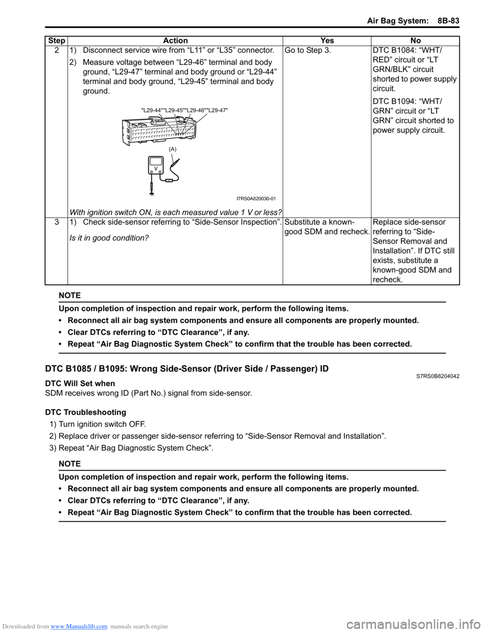
2 1) Disconnect service wire from “L11” or “L35” connector.
2) Measure voltage between “L29-46” terminal and body ground, “L29-47” terminal and body ground or “L29-44”
terminal and body ground, “L29-45” terminal and body
ground.
With ignition switch ON, is each measured value 1 V or less? Go to Step 3. DTC B1084: “WHT/
RED” circuit or “LT
GRN/BLK” circuit
shorted to power supply
circuit.
DTC B1094: “WHT/
GRN” circuit or “LT
GRN” circuit shorted to
power supply circuit.
3 1) Check side-sensor referring to “Side-Sensor Inspection”. Is it in good condition? Substitute a known-
good SDM and recheck.
Replace side-sensor
referring to “Side-
Sensor Removal and
Installation”. If DTC still
exists, substitute a
known-good SDM and
recheck.
Step Action Yes No
(A)
"L29-45""L29-46" "L29-47"
"L29-44"
I7RS0A820030-01
Page 1123 of 1496
Downloaded from www.Manualslib.com manuals search engine Air Bag System: 8B-85
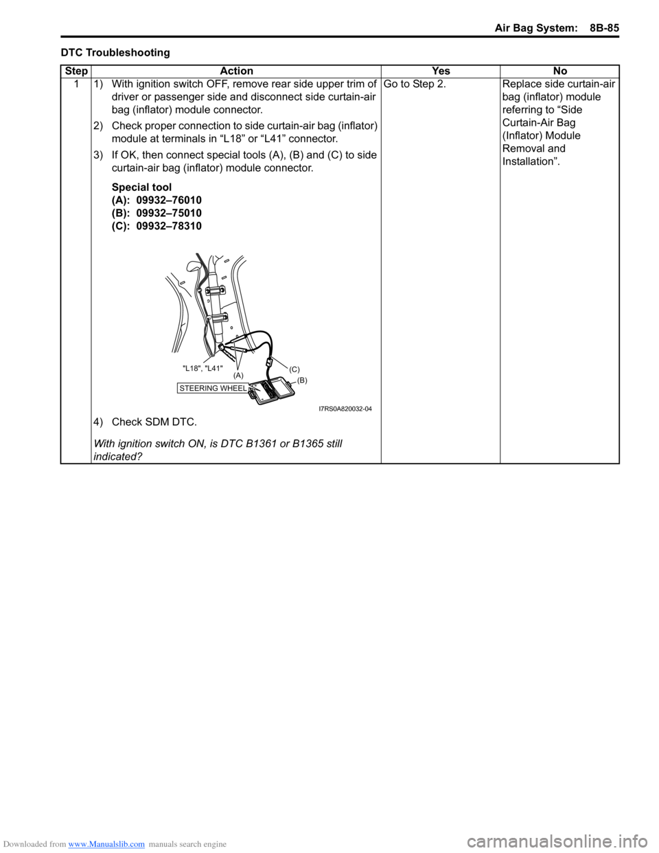
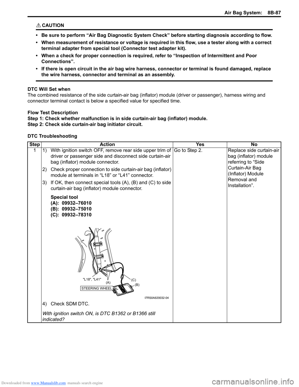
DTC TroubleshootingStep Action Yes No 1 1) With ignition switch OFF, remove rear side upper trim of driver or passenger side and disconnect side curtain-air
bag (inflator) module connector.
2) Check proper connection to side curtain-air bag (inflator) module at terminals in “L18” or “L41” connector.
3) If OK, then connect special tools (A), (B) and (C) to side curtain-air bag (inflator) module connector.
Special tool
(A): 09932–76010
(B): 09932–75010
(C): 09932–78310
4) Check SDM DTC.
With ignition switch ON, is DTC B1361 or B1365 still
indicated? Go to Step 2. Replace side curtain-air
bag (inflator) module
referring to “Side
Curtain-Air Bag
(Inflator) Module
Removal and
Installation”.
STEERING WHEEL(B)
(C)
(A)
"L18", "L41"
I7RS0A820032-04
Page 1125 of 1496
Downloaded from www.Manualslib.com manuals search engine Air Bag System: 8B-87
CAUTION!
• Be sure to perform “Air Bag Diagnostic System Check” before starting diagnosis according to flow.
• When measurement of resistance or voltage is required in this flow, use a tester along with a correct terminal adapter from special tool (Connector test adapter kit).
• When a check for proper connection is required, refer to “Inspection of Intermittent and Poor Connections”.
• If there is open circuit in the air bag wire harnes s, connector or terminal is found damaged, replace
the wire harness, connector and terminal as an assembly.
DTC Will Set when
The combined resistance of the side curtain-air bag (inflator) module (driver or passenger), harness wiring and
connector terminal contact is below a specified value for specified time.
Flow Test Description
Step 1: Check whether malfunction is in side curtain-air bag (inflator) module.
Step 2: Check side curtain-air bag initiator circuit.
DTC Troubleshooting
Step Action YesNo
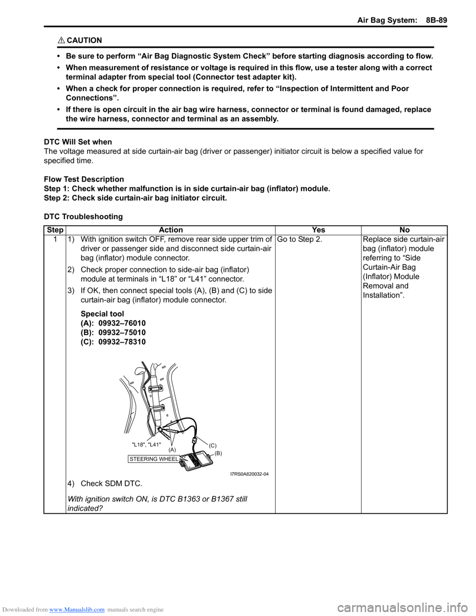
1 1) With ignition switch OFF, remove rear side upper trim of driver or passenger side and disconnect side curtain-air
bag (inflator) module connector.
2) Check proper connection to side curtain-air bag (inflator) module at terminals in “L18” or “L41” connector.
3) If OK, then connect special tools (A), (B) and (C) to side curtain-air bag (inflator) module connector.
Special tool
(A): 09932–76010
(B): 09932–75010
(C): 09932–78310
4) Check SDM DTC.
With ignition switch ON, is DTC B1362 or B1366 still
indicated? Go to Step 2.
Replace side curtain-air
bag (inflator) module
referring to “Side
Curtain-Air Bag
(Inflator) Module
Removal and
Installation”.
STEERING WHEEL(B)
(C)
(A)
"L18", "L41"
I7RS0A820032-04
Page 1127 of 1496
Downloaded from www.Manualslib.com manuals search engine Air Bag System: 8B-89
CAUTION!
• Be sure to perform “Air Bag Diagnostic System Check” before starting diagnosis according to flow.
• When measurement of resistance or voltage is required in this flow, use a tester along with a correct terminal adapter from special tool (Connector test adapter kit).
• When a check for proper connection is required, refer to “Inspection of Intermittent and Poor Connections”.
• If there is open circuit in the air bag wire harnes s, connector or terminal is found damaged, replace
the wire harness, connector and terminal as an assembly.
DTC Will Set when
The voltage measured at side curtain-air bag (driver or passenger) initiator circuit is below a specified value for
specified time.
Flow Test Description
Step 1: Check whether malfunction is in side curtain-air bag (inflator) module.
Step 2: Check side curtain-air bag initiator circuit.
DTC Troubleshooting
Step Action YesNo
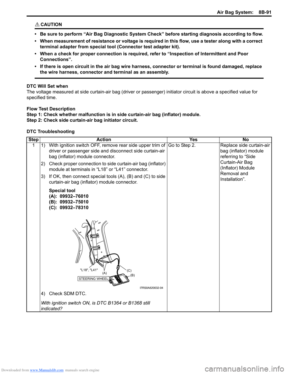
1 1) With ignition switch OFF, remove rear side upper trim of driver or passenger side and disconnect side curtain-air
bag (inflator) module connector.
2) Check proper connection to side-air bag (inflator) module at terminals in “L18” or “L41” connector.
3) If OK, then connect special tools (A), (B) and (C) to side curtain-air bag (inflator) module connector.
Special tool
(A): 09932–76010
(B): 09932–75010
(C): 09932–78310
4) Check SDM DTC.
With ignition switch ON, is DTC B1363 or B1367 still
indicated? Go to Step 2.
Replace side curtain-air
bag (inflator) module
referring to “Side
Curtain-Air Bag
(Inflator) Module
Removal and
Installation”.
STEERING WHEEL(B)
(C)
(A)
"L18", "L41"
I7RS0A820032-04
Page 1129 of 1496
Downloaded from www.Manualslib.com manuals search engine Air Bag System: 8B-91
CAUTION!
• Be sure to perform “Air Bag Diagnostic System Check” before starting diagnosis according to flow.
• When measurement of resistance or voltage is required in this flow, use a tester along with a correct terminal adapter from special tool (Connector test adapter kit).
• When a check for proper connection is required, refer to “Inspection of Intermittent and Poor Connections”.
• If there is open circuit in the air bag wire harnes s, connector or terminal is found damaged, replace
the wire harness, connector and terminal as an assembly.
DTC Will Set when
The voltage measured at side curtain-air bag (driver or passenger) initiator circuit is above a specified value for
specified time.
Flow Test Description
Step 1: Check whether malfunction is in side curtain-air bag (inflator) module.
Step 2: Check side curtain-air bag initiator circuit.
DTC Troubleshooting
Step Action YesNo
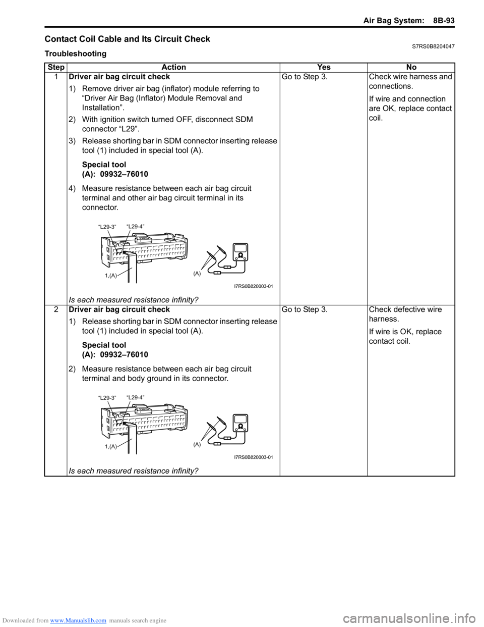
1 1) With ignition switch OFF, remove rear side upper trim of driver or passenger side and disconnect side curtain-air
bag (inflator) module connector.
2) Check proper connection to side curtain-air bag (inflator) module at terminals in “L18” or “L41” connector.
3) If OK, then connect special tools (A), (B) and (C) to side curtain-air bag (inflator) module connector.
Special tool
(A): 09932–76010
(B): 09932–75010
(C): 09932–78310
4) Check SDM DTC.
With ignition switch ON, is DTC B1364 or B1368 still
indicated? Go to Step 2.
Replace side curtain-air
bag (inflator) module
referring to “Side
Curtain-Air Bag
(Inflator) Module
Removal and
Installation”.
STEERING WHEEL(B)
(C)
(A)
"L18", "L41"
I7RS0A820032-04
Page 1131 of 1496
Downloaded from www.Manualslib.com manuals search engine Air Bag System: 8B-93
Contact Coil Cable and Its Circuit CheckS7RS0B8204047
TroubleshootingStep Action Yes No 1 Driver air bag circuit check
1) Remove driver air bag (inflator) module referring to
“Driver Air Bag (Inflator) Module Removal and
Installation”.
2) With ignition switch turned OFF, disconnect SDM connector “L29”.
3) Release shorting bar in SDM connector inserting release tool (1) included in special tool (A).
Special tool
(A): 09932–76010
4) Measure resistance between each air bag circuit terminal and other air bag circuit terminal in its
connector.
Is each measured resistance infinity? Go to Step 3. Check wire harness and
connections.
If wire and connection
are OK, replace contact
coil.
2 Driver air bag circuit check
1) Release shorting bar in SDM connector inserting release
tool (1) included in special tool (A).
Special tool
(A): 09932–76010
2) Measure resistance between each air bag circuit terminal and body ground in its connector.
Is each measured resistance infinity? Go to Step 3. Check defective wire
harness.
If wire is OK, replace
contact coil.
“L29-4”
“L29-3”
1,(A)(A)
I7RS0B820003-01
“L29-4”
“L29-3”
1,(A)(A)
I7RS0B820003-01
Page 1163 of 1496
Downloaded from www.Manualslib.com manuals search engine Air Bag System: 8B-125
Specifications
Tightening Torque SpecificationsS7RS0B8207001
NOTE
The specified tightening torque is also described in the following.
“Air Bag System Components, Wiring and Connectors Location”
Reference:
For the tightening torque of fastener not specified in this section, refer to “Fasteners Information in Section 0A”.
Special Tools and Equipment
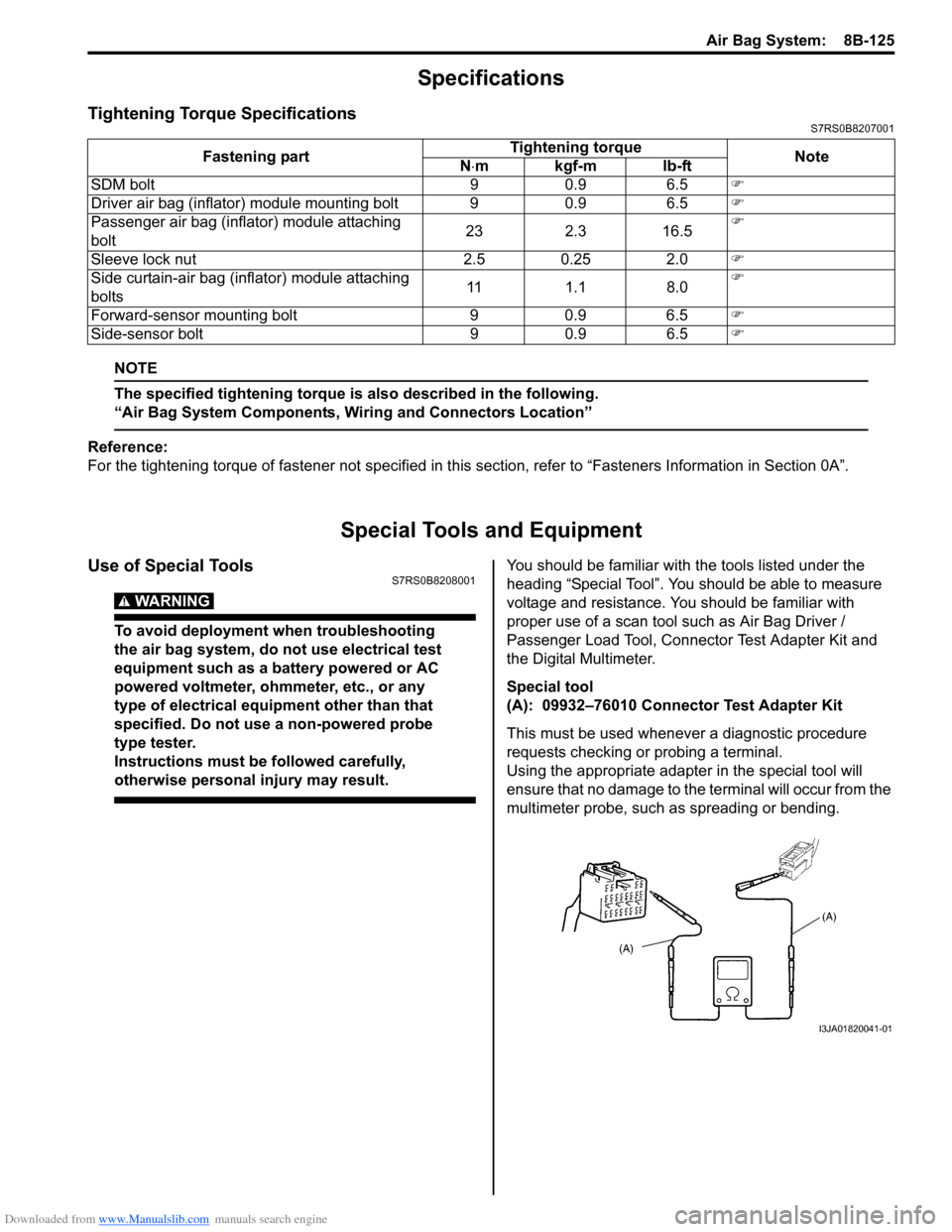
Use of Special ToolsS7RS0B8208001
WARNING!
To avoid deployment when troubleshooting
the air bag system, do not use electrical test
equipment such as a battery powered or AC
powered voltmeter, ohmmeter, etc., or any
type of electrical equipment other than that
specified. Do not use a non-powered probe
type tester.
Instructions must be followed carefully,
otherwise personal injury may result.
You should be familiar with the tools listed under the
heading “Special Tool”. You should be able to measure
voltage and resistance. You should be familiar with
proper use of a scan tool such as Air Bag Driver /
Passenger Load Tool, Connector Test Adapter Kit and
the Digital Multimeter.
Special tool
(A): 09932–76010 Connector Test Adapter Kit
This must be used whenever a diagnostic procedure
requests checking or probing a terminal.
Using the appropriate adapter in the special tool will
ensure that no damage to the terminal will occur from the
multimeter probe, such as spreading or bending.
Fastening part
Tightening torque
Note
N ⋅mkgf-mlb-ft
SDM bolt 9 0.9 6.5 �)
Driver air bag (inflator) module mounting bolt 9 0.9 6.5 �)
Passenger air bag (inflator) module attaching
bolt 23 2.3 16.5�)
Sleeve lock nut 2.5 0.25 2.0 �)
Side curtain-air bag (inflator) module attaching
bolts 11 1.1 8.0�)
Forward-sensor mounting bolt 9 0.9 6.5 �)
Side-sensor bolt 9 0.9 6.5 �)
I3JA01820041-01
Page 1296 of 1496
Downloaded from www.Manualslib.com manuals search engine 9C-1 Instrumentation / Driver Info. / Horn:
Body, Cab and Accessories
Instrumentation / Driver Info. / Horn
Precautions
Precautions in Diagnosing Troubles for Combination MeterS7RS0B9300001
Combination meter uses signals (information) from each control module by CAN communication to control
speedometer, tachometer, engine coolant temp meter, warning light and indicator light (other than air bag warning
light, high beam indicator light, EPS warn ing light and turn signal indicator light). Therefore, check that no DTC is
detected in each module before performing combination me ter symptom diagnosis. If any DTC is detected, correct
trouble indicated by that DTC troubleshooting first.
General Description
CAN Communication System DescriptionS7RS0B9301001
Refer to “CAN Communication System Description in Section 1A” for Can communication system description.
Combination meter communicates control data with each control module as follows.
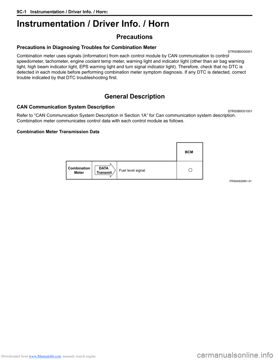
Combination Meter Transmission Data
BCM
Combination Meter DATA
TransmitFuel level signal
I7RS0A930001-01