ect removal SUZUKI SWIFT 2008 2.G Service Workshop Manual
[x] Cancel search | Manufacturer: SUZUKI, Model Year: 2008, Model line: SWIFT, Model: SUZUKI SWIFT 2008 2.GPages: 1496, PDF Size: 34.44 MB
Page 1325 of 1496
Downloaded from www.Manualslib.com manuals search engine Wipers / Washers: 9D-8
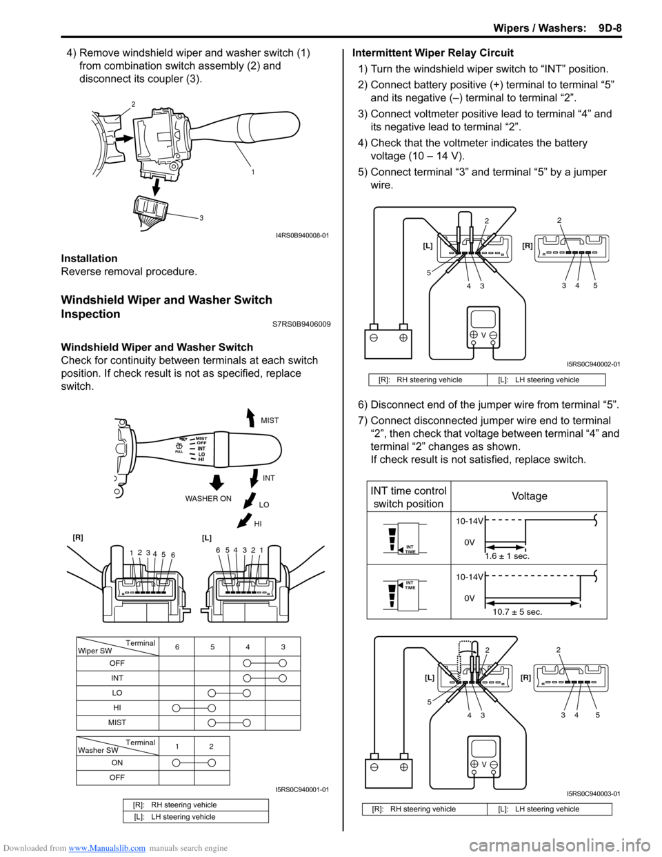
4) Remove windshield wiper and washer switch (1) from combination swit ch assembly (2) and
disconnect its coupler (3).
Installation
Reverse removal procedure.
Windshield Wiper and Washer Switch
Inspection
S7RS0B9406009
Windshield Wiper and Washer Switch
Check for continuity between terminals at each switch
position. If check result is not as specified, replace
switch. Intermittent Wiper Relay Circuit
1) Turn the windshield wiper switch to “INT” position.
2) Connect battery positive (+ ) terminal to terminal “5”
and its negative (–) terminal to terminal “2”.
3) Connect voltmeter positive lead to terminal “4” and its negative lead to terminal “2”.
4) Check that the voltmeter indicates the battery voltage (10 – 14 V).
5) Connect terminal “3” and terminal “5” by a jumper wire.
6) Disconnect end of the jumper wire from terminal “5”.
7) Connect disconnected jumper wire end to terminal “2”, then check that voltage between terminal “4” and
terminal “2” changes as shown.
If check result is not satisfied, replace switch.
[R]: RH steering vehicle
[L]: LH steering vehicle
1
2
3
I4RS0B940008-01
Terminal
Wiper SW
OFF
INT 6543
MIST
Terminal
Washer SW
OFF 12
ONLO
HI
654321
MIST
INT
LO
HI
WASHER ON
1
2
3
4 5 6
[R]
[L]
I5RS0C940001-01
[R]: RH steering vehicle [L]: LH steering vehicle
[R]: RH steering vehicle [L]: LH steering vehicle
V
2
34
52
34 5
[L] [R]
I5RS0C940002-01
V
INT
TIME
INT
TIME
INT time control
switch position Voltage
10-14V
0V 1.6 ± 1 sec.
10-14V
0V 10.7 ± 5 sec.
2
34
52
34 5
[L]
[R]
I5RS0C940003-01
Page 1326 of 1496
Downloaded from www.Manualslib.com manuals search engine 9D-9 Wipers / Washers:
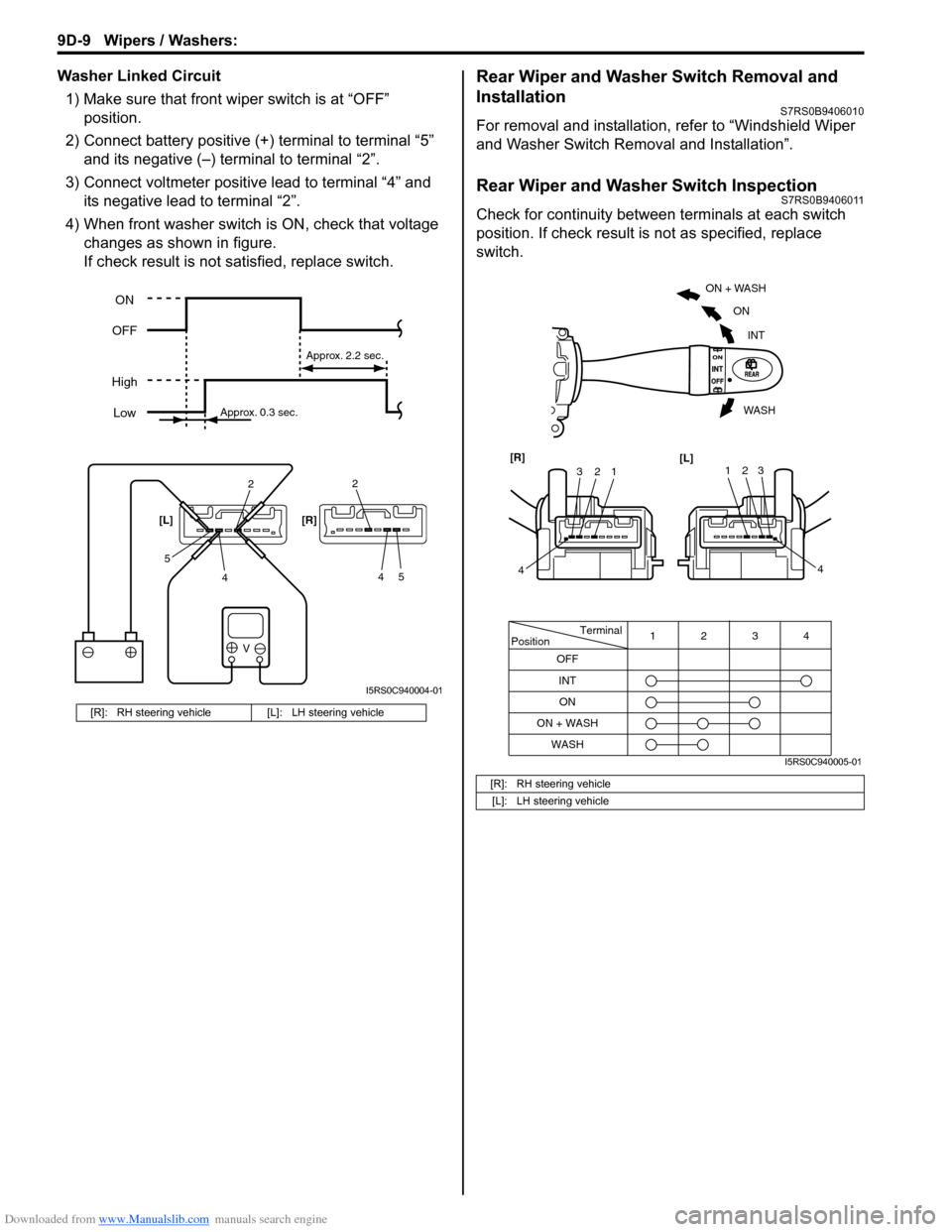
Washer Linked Circuit1) Make sure that front wiper switch is at “OFF” position.
2) Connect battery positive (+ ) terminal to terminal “5”
and its negative (–) terminal to terminal “2”.
3) Connect voltmeter positive lead to terminal “4” and its negative lead to terminal “2”.
4) When front washer switch is ON, check that voltage
changes as shown in figure.
If check result is not satisfied, replace switch.Rear Wiper and Washer Switch Removal and
Installation
S7RS0B9406010
For removal and installation, refer to “Windshield Wiper
and Washer Switch Removal and Installation”.
Rear Wiper and Washer Switch InspectionS7RS0B9406011
Check for continuity between terminals at each switch
position. If check result is not as specified, replace
switch.
[R]: RH steering vehicle [L]: LH steering vehicle
V
2
4
52
45
[L] [R]
ON
OFF
High Low
Approx. 0.3 sec. Approx. 2.2 sec.
I5RS0C940004-01
[R]: RH steering vehicle
[L]: LH steering vehicle
Terminal
Position
OFF
INT 4
3
12
WASH ON
ON + WASH
ON + WASH
INT
ON
WASH
123
4
[R]
[L]123
4
I5RS0C940005-01
Page 1327 of 1496
Downloaded from www.Manualslib.com manuals search engine Wipers / Washers: 9D-10
Rear Wiper Relay Removal and InstallationS7RS0B9406012
Removal1) Disconnect negative (–) cable at battery.
2) Remove junction block assembly referring to “BCM (Included in Junction Block Assembly) Removal and
Installation in Section 10B”.
3) Remove rear wiper relay.
Installation
Reverse removal procedure for installation.
Rear Wiper Relay InspectionS7RS0B9406013
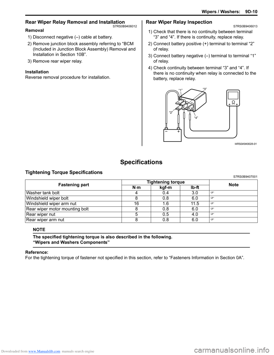
1) Check that there is no continuity between terminal “3” and “4”. If there is continuity, replace relay.
2) Connect battery positive (+ ) terminal to terminal “2”
of relay.
3) Connect battery negative (–) terminal to terminal “1” of relay.
4) Check continuity between terminal “3” and “4”. If
there is no continuity when relay is connected to the
battery, replace relay.
Specifications
Tightening Torque SpecificationsS7RS0B9407001
NOTE
The specified tightening torque is also described in the following.
“Wipers and Washers Components”
Reference:
For the tightening torque of fastener not specified in this section, refer to “Fasteners Information in Section 0A”.
“4”
“2” “1”
“3”
I4RS0A940028-01
Fastening part Tightening torque
Note
N ⋅mkgf-mlb-ft
Washer tank bolt 4 0.4 3.0 �)
Windshield wiper bolt 8 0.8 6.0 �)
Windshield wiper arm nut 16 1.6 11.5 �)
Rear wiper motor mounting bolt 8 0.8 6.0 �)
Rear wiper nut 5 0.5 4.0 �)
Rear wiper arm nut 8 0.8 6.0 �)
Page 1328 of 1496
Downloaded from www.Manualslib.com manuals search engine 9E-1 Glass / Windows / Mirrors:
Body, Cab and Accessories
Glass / Windows / Mirrors
General Description
Rear End Door Window Defogger System DescriptionS7RS0B9501001
The rear end door window defogger is controlled by BCM. For the BCM description refer to “BCM General Description
in Section 10B”.
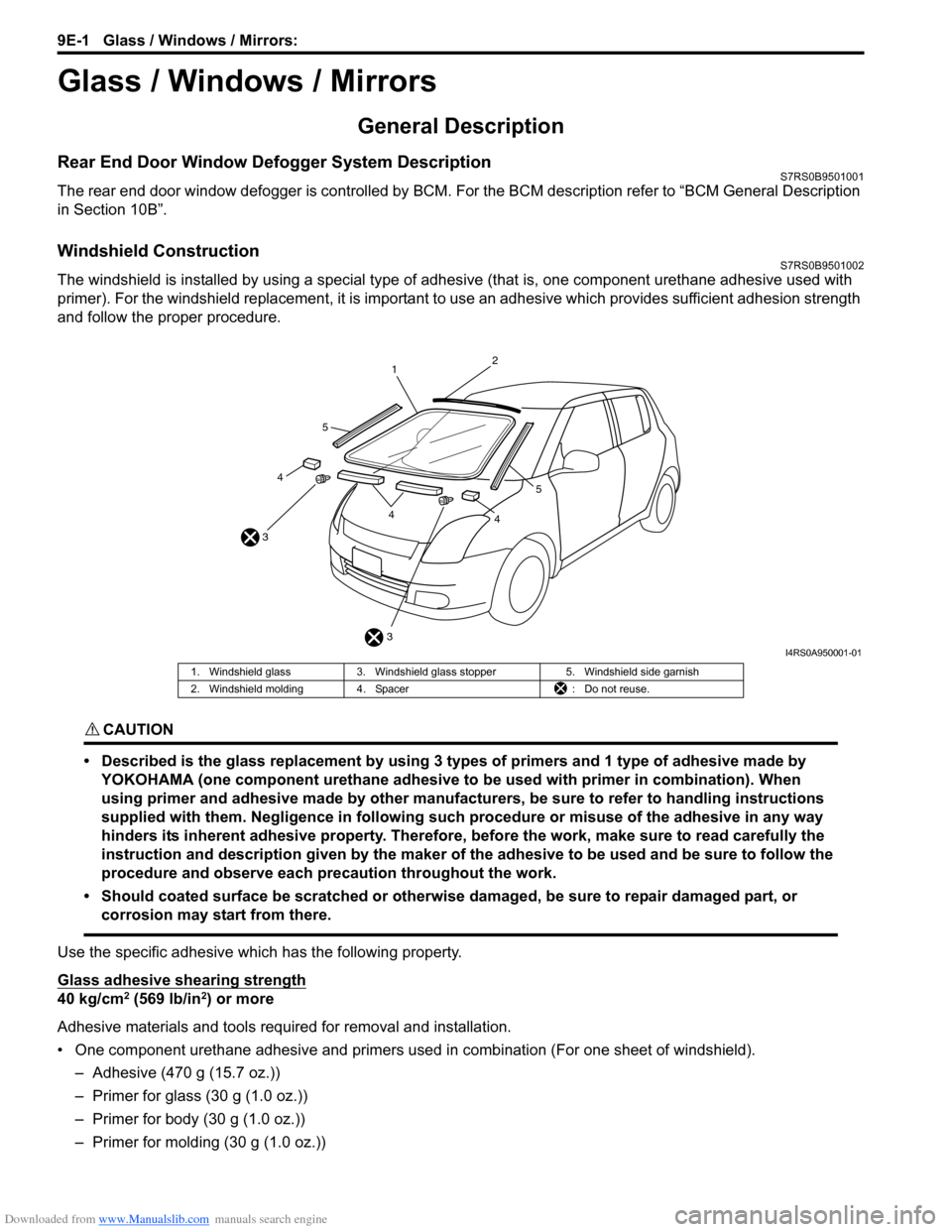
Windshield ConstructionS7RS0B9501002
The windshield is installed by using a special type of adhesive (that is, one component urethane adhesive used with
primer). For the windshield replacement, it is important to use an adhesive which provides sufficient adhesion strength
and follow the proper procedure.
CAUTION!
• Described is the glass replacement by using 3 types of primers and 1 type of adhesive made by YOKOHAMA (one component urethane adhesive to be used with primer in combination). When
using primer and adhesive made by other manufacturers, be sure to refer to handling instructions
supplied with them. Negligence in following such procedure or misuse of the adhesive in any way
hinders its inherent adhesive property. Therefore, before the work, make sure to read carefully the
instruction and description given by the maker of the adhesive to be used and be sure to follow the
procedure and observe each precaution throughout the work.
• Should coated surface be scratched or otherwise damaged, be sure to repair damaged part, or corrosion may start from there.
Use the specific adhesive which has the following property.
Glass adhesive shearing strength
40 kg/cm2 (569 lb/in2) or more
Adhesive materials and tools required for removal and installation.
• One component urethane adhesive and primers used in combination (For one sheet of windshield). – Adhesive (470 g (15.7 oz.))
– Primer for glass (30 g (1.0 oz.))
– Primer for body (30 g (1.0 oz.))
– Primer for molding (30 g (1.0 oz.))
3
3 1
2
44
4
5
5
I4RS0A950001-01
1. Windshield glass
3. Windshield glass stopper 5. Windshield side garnish
2. Windshield molding 4. Spacer : Do not reuse.
Page 1331 of 1496
Downloaded from www.Manualslib.com manuals search engine Glass / Windows / Mirrors: 9E-4
Repair Instructions
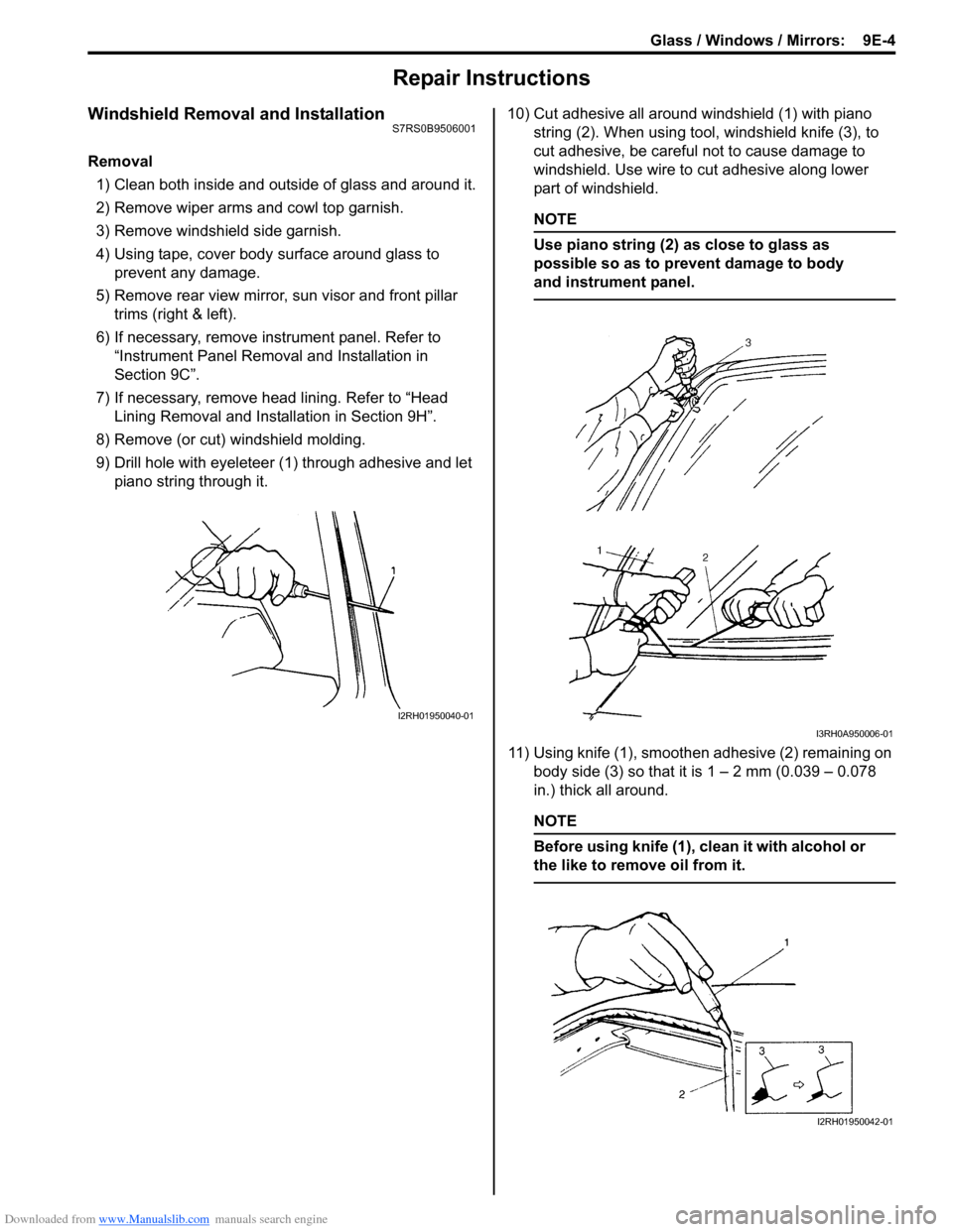
Windshield Removal and InstallationS7RS0B9506001
Removal1) Clean both inside and outside of glass and around it.
2) Remove wiper arms and cowl top garnish.
3) Remove windshield side garnish.
4) Using tape, cover body surface around glass to prevent any damage.
5) Remove rear view mirror , sun visor and front pillar
trims (right & left).
6) If necessary, remove instrument panel. Refer to “Instrument Panel Removal and Installation in
Section 9C”.
7) If necessary, remove he ad lining. Refer to “Head
Lining Removal and Installation in Section 9H”.
8) Remove (or cut) windshield molding.
9) Drill hole with eyeleteer (1 ) through adhesive and let
piano string through it. 10) Cut adhesive all around windshield (1) with piano
string (2). When using tool, windshield knife (3), to
cut adhesive, be careful not to cause damage to
windshield. Use wire to cut adhesive along lower
part of windshield.
NOTE
Use piano string (2) as close to glass as
possible so as to prevent damage to body
and instrument panel.
11) Using knife (1), smoothen adhesive (2) remaining on body side (3) so that it is 1 – 2 mm (0.039 – 0.078
in.) thick all around.
NOTE
Before using knife (1), clean it with alcohol or
the like to remove oil from it.
I2RH01950040-01
I3RH0A950006-01
I2RH01950042-01
Page 1335 of 1496
Downloaded from www.Manualslib.com manuals search engine Glass / Windows / Mirrors: 9E-8
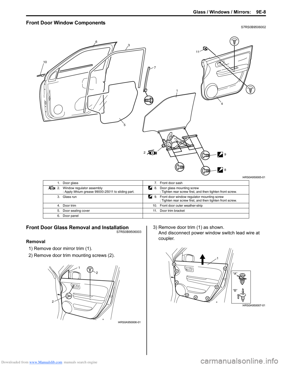
Front Door Window ComponentsS7RS0B9506002
Front Door Glass Removal and InstallationS7RS0B9506003
Removal1) Remove door mirror trim (1).
2) Remove door trim mounting screws (2). 3) Remove door trim (1) as shown.
And disconnect power window switch lead wire at
coupler.
10 6
3
1
7
11
5
2 9
8
4
I4RS0A950005-01
1. Door glass 7. Front door sash
2. Window regulator assembly : Apply lithium grease 99000-25011 to sliding part. 8. Door glass mounting screw
: Tighten rear screw first, and then tighten front screw.
3. Glass run 9. Front door window regulator mounting screw
: Tighten rear screw first, and then tighten front screw.
4. Door trim 10. Front door outer weather-strip
5. Door sealing cover 11. Door trim bracket
6. Door panel
2 2
1
I4RS0A950006-01
“B”
“A”
“B”
“A”
“B”“A”
“A”
“A”“A”“A”
1
I4RS0A950007-01
Page 1336 of 1496
Downloaded from www.Manualslib.com manuals search engine 9E-9 Glass / Windows / Mirrors:
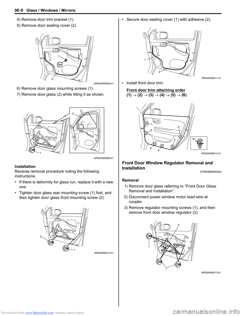
4) Remove door trim bracket (1).
5) Remove door sealing cover (2).
6) Remove door glass mounting screws (1).
7) Remove door glass (2) while tilting it as shown.
Installation
Reverse removal procedure noting the following
instructions.
• If there is deformity for glass run, replace it with a new one.
• Tighten door glass rear mounting screw (1) first, and then tighten door glass front mounting screw (2). • Secure door sealing cover (1) with adhesive (2).
• Install front door trim.
Front door trim attaching order
(1) → (2) → (3) → (4) → (5) → (6)
Front Door Window Regulator Removal and
Installation
S7RS0B9506004
Removal
1) Remove door glass referring to “Front Door Glass Removal and Installation”.
2) Disconnect power window motor lead wire at coupler.
3) Remove regulator mounting screws (1), and then remove front door window regulator (2).
1
2
I4RS0A950008-01
2
1
I4RS0A950009-01
1
2
I4RS0A950010-01
2
1
I4RS0A950011-01
“A”“A”
“A”
“A”
“A”“A”“A”
1 2
3
4
5 6
I4RS0A950012-01
1
1
2
I4RS0A950013-01
Page 1337 of 1496
Downloaded from www.Manualslib.com manuals search engine Glass / Windows / Mirrors: 9E-10
Installation
Reverse removal procedure noting the following
instruction.
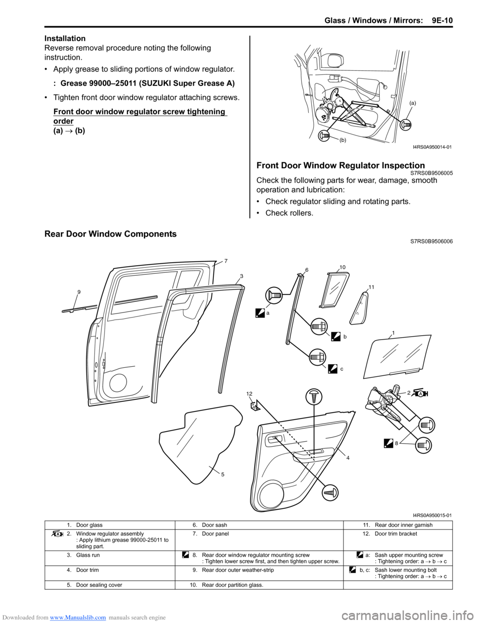
• Apply grease to sliding portions of window regulator.: Grease 99000–25011 (SUZUKI Super Grease A)
• Tighten front door window regulator attaching screws. Front door window regulator screw tightening
order
(a) → (b)
Front Door Window Regulator InspectionS7RS0B9506005
Check the following parts for wear, dama ge, smooth
operation and lubrication:
• Check regulator sliding and rotating parts.
• Check rollers.
Rear Door Window ComponentsS7RS0B9506006
(a)
(b)
I4RS0A950014-01
9
7
3610
11
b
c
12
5 2
8
4
a
1
I4RS0A950015-01
1. Door glass
6. Door sash 11. Rear door inner garnish
2. Window regulator assembly : Apply lithium grease 99000-25011 to
sliding part. 7. Door panel
12. Door trim bracket
3. Glass run 8. Rear door window regulator mounting screw
: Tighten lower screw first, and then tighten upper screw. a: Sash upper mounting screw
: Tightening order: a → b → c
4. Door trim 9. Rear door outer weather-strip b, c: Sash lower mounting bolt
: Tightening order: a → b → c
5. Door sealing cover 10. Rear door partition glass.
Page 1338 of 1496
Downloaded from www.Manualslib.com manuals search engine 9E-11 Glass / Windows / Mirrors:
Rear Door Glass Removal and InstallationS7RS0B9506007
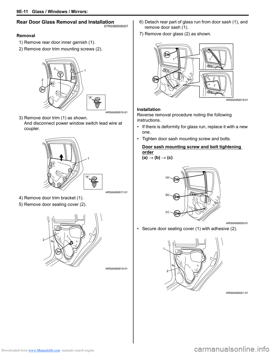
Removal1) Remove rear door inner garnish (1).
2) Remove door trim mounting screws (2).
3) Remove door trim (1) as shown. And disconnect power wi ndow switch lead wire at
coupler.
4) Remove door trim bracket (1).
5) Remove door sealing cover (2). 6) Detach rear part of glass run from door sash (1), and
remove door sash (1).
7) Remove door glass (2) as shown.
Installation
Reverse removal procedure noting the following
instructions.
• If there is deformity for glass run, replace it with a new one.
• Tighten door sash mounting screw and bolts.
Door sash mounting screw and bolt tightening
order
(a) → (b) → (c)
• Secure door sealing cover (1) with adhesive (2).
“A”
“A”
“A”
2
2 1
I4RS0A950016-01
“A”
“A”
“A”
“A”“A”
“A”
“A”
1
I4RS0A950017-01
1
2
I4RS0A950018-01
1
1
2
I4RS0A950019-01
(a)
(b)
(c)
I4RS0A950020-01
1
2
I4RS0A950021-01
Page 1339 of 1496
Downloaded from www.Manualslib.com manuals search engine Glass / Windows / Mirrors: 9E-12
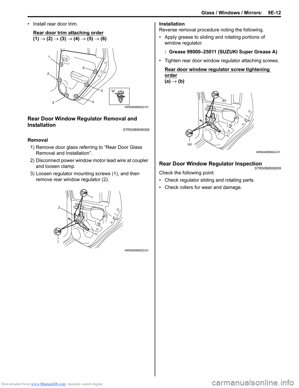
• Install rear door trim.Rear door trim attaching order
(1) → (2) → (3) → (4) → (5) → (6)
Rear Door Window Regulator Removal and
Installation
S7RS0B9506008
Removal
1) Remove door glass referring to “Rear Door Glass Removal and Installation”.
2) Disconnect power window mo tor lead wire at coupler
and loosen clamp.
3) Loosen regulator mounting screws (1), and then remove rear window regulator (2). Installation
Reverse removal procedure noting the following.
• Apply grease to sliding and rotating portions of
window regulator.
: Grease 99000–25011 (SUZUKI Super Grease A)
• Tighten rear door window regulator attaching screws. Rear door window regulator screw tightening
order
(a) → (b)
Rear Door Window Regulator InspectionS7RS0B9506009
Check the following point:
• Check regulator sliding and rotating parts.
• Check rollers for wear and damage.
“A”
1
2
3 45
6
“A”
“A”
“A”“A”
“A”
“A”
I4RS0A950022-01
1
1 2
I4RS0A950023-01
(a) (b)
I4RS0A950024-01