123 SUZUKI SWIFT 2008 2.G Service Owner's Manual
[x] Cancel search | Manufacturer: SUZUKI, Model Year: 2008, Model line: SWIFT, Model: SUZUKI SWIFT 2008 2.GPages: 1496, PDF Size: 34.44 MB
Page 595 of 1496
Downloaded from www.Manualslib.com manuals search engine Electronic Stability Program: 4F-21
Stability control (ACTIVE, INACTIVE): This indicates
stability control in acti vation / deactivation.
TCS control (brake) ( ACTIVE, INACTIVE): This
indicates brake function of TCS in activation /
deactivation.
TCS control (engine) (ACTIVE, INACTIVE): This
indicates torque control of TCS in activation /
deactivation. ESP®
off state (cont) (ESP ® ON, ESP ® OFF): State
of ESP ® OFF switch.
Steering angle Sen (Neutral, NON newtral): This
indicates steering wheel angle measured by steering
angle sensor is in straight-ahead or not.
Visual InspectionS7RS0B4604059
Check the following parts and systems visually.
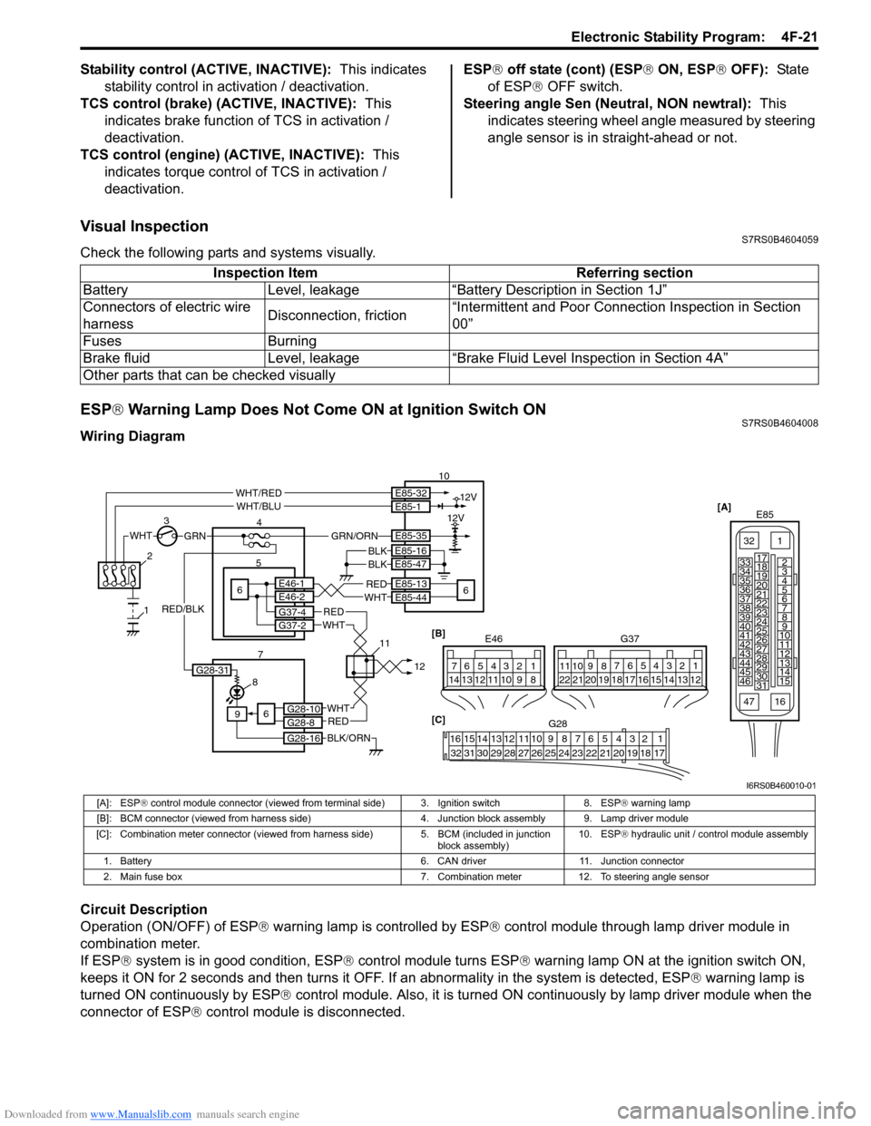
ESP ® Warning Lamp Does Not Come ON at Ignition Switch ONS7RS0B4604008
Wiring Diagram
Circuit Description
Operation (ON/OFF) of ESP ® warning lamp is controlled by ESP ® control module through lamp driver module in
combination meter.
If ESP ® system is in good condition, ESP ® control module turns ESP ® warning lamp ON at the ignition switch ON,
keeps it ON for 2 seconds and then turns it OFF. If an abnormality in the system is detected, ESP ® warning lamp is
turned ON continuously by ESP ® control module. Also, it is turned ON continuously by lamp driver module when the
connector of ESP ® control module is disconnected.Inspection Item Referring section
Battery Level, leakage “Battery Description in Section 1J”
Connectors of electric wire
harness Disconnection, friction“Intermittent and Poor Connec
tion Inspection in Section
00”
Fuses Burning
Brake fluid Level, leakage “Brake Fluid Level Inspection in Section 4A”
Other parts that can be checked visually
[A] E85
161
15
2
3
4
5
6
7
8
9
10
11
12
13
14
17
18
19
20
21
22
23
24
25
26
27
28
29
30
31
3233
34
35
36
37
38
39
40
41
42
43
44
45
46
47
WHTGRN
3
E85-13
E85-44REDWHT6 5E46-1E46-2
4 10
6
E85-16
E85-47BLKBLK
8
9
BLK/ORN
REDWHT
REDWHT
G37-4G37-2
G28-10G28-8
G28-16
12V
12VE85-32E85-1
E85-35
WHT/REDWHT/BLU
GRN/ORN
6
2
1
7 1112[B]
G37
E46124
53
67
891011121314124
53
67
891011
1213141516171819202122
[C] G28
12345678910111213141516
17181920212223242526272829303132
G28-31
RED/BLK
I6RS0B460010-01
[A]: ESP ® control module connector (viewed from terminal side) 3. Ignition switch 8. ESP ® warning lamp
[B]: BCM connector (viewed from harness side) 4. Junction block assembly 9. Lamp driver module
[C]: Combination meter connector (viewed from harness side) 5. BCM (included in junction
block assembly) 10. ESP
® hydraulic unit / control module assembly
1. Battery 6. CAN driver 11. Junction connector
2. Main fuse box 7. Combination meter 12. To steering angle sensor
Page 597 of 1496
Downloaded from www.Manualslib.com manuals search engine Electronic Stability Program: 4F-23
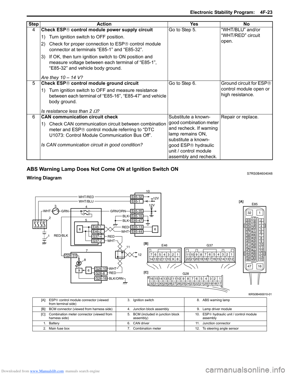
ABS Warning Lamp Does Not Come ON at Ignition Switch ONS7RS0B4604048
Wiring Diagram4
Check ESP ® control module power supply circuit
1) Turn ignition switch to OFF position.
2) Check for proper connection to ESP ® control module
connector at terminals “E85-1” and “E85-32”.
3) If OK, then turn ignition switch to ON position and measure voltage between each terminal of “E85-1”,
“E85-32” and vehicle body ground.
Are they 10 – 14 V? Go to Step 5. “WHT/BLU” and/or
“WHT/RED” circuit
open.
5 Check ESP ® control module ground circuit
1) Turn ignition switch to OFF and measure resistance between each terminal of “E85-16”, “E85-47” and vehicle
body ground.
Is resistance less than 2
Ω? Go to Step 6.
Ground circuit for ESP®
control module open or
high resistance.
6 CAN communication circuit check
1) Check CAN communication circuit between combination
meter and ESP ® control module referring to “DTC
U1073: Control Module Communication Bus Off”.
Is CAN communication circuit in good condition? Substitute a known-
good combination meter
and recheck. If warning
lamp remains ON,
substitute a known-
good ESP
® hydraulic
unit / control module
assembly and recheck. Repair or replace.
Step
Action YesNo
[A]
E85
161
15
2
3
4
5
6
7
8
9
10
11
12
13
14
17
18
19
20
21
22
23
24
25
26
27
28
29
30
31
3233
34
35
36
37
38
39
40
41
42
43
44
45
46
47
WHTGRN
3
E85-13
E85-44REDWHT6 5E46-1E46-2
4 10
6
E85-16
E85-47BLKBLK
8
9
BLK/ORN
REDWHT
REDWHT
G37-4G37-2
G28-10G28-8
G28-16
12V
12VE85-32E85-1
E85-35
WHT/REDWHT/BLU
GRN/ORN
6
2
1
7 1112[B]
G37
E46124
53
67
891011121314124
53
67
891011
1213141516171819202122
[C] G28
12345678910111213141516
17181920212223242526272829303132
G28-31
RED/BLK
I6RS0B460010-01
[A]: ESP ® control module connector (viewed
from terminal side) 3. Ignition switch 8. ABS warning lamp
[B]: BCM connector (viewed from harness side) 4. Junction block assembly 9. Lamp driver module
[C]: Combination meter connector (viewed from harness side) 5. BCM (included in junction block
assembly) 10. ESP
® hydraulic unit / control module
assembly
1. Battery 6. CAN driver11. Junction connector
2. Main fuse box 7. Combination meter12. To steering angle sensor
Page 598 of 1496
Downloaded from www.Manualslib.com manuals search engine 4F-24 Electronic Stability Program:
Circuit Description
Operation (ON/OFF) of ABS warning lamp is controlled by ESP® control module through lamp driver module in
combination meter.
If antilock brake system is in good condition, ESP ® control module turns ABS warning lamp ON at the ignition switch
ON, keeps it ON for 2 seconds and then turns it OFF. If an abnormality in the system is detected, ABS warning lamp is
turned ON continuously by ESP ® control module. Also, it is turned ON continuously by lamp driver module when the
connector of ESP ® control module is disconnected.
Troubleshooting
Refer to “Troubleshooting” under “ESP ® Warning Lamp Does Not Come ON at Ignition Switch ON”.
ABS Warning Lamp Comes ON SteadyS7RS0B4604049
Wiring Diagram
Refer to “Wiring Diagram” under “ABS Warning Lamp Does Not Come ON at Ignition Switch ON”.
Circuit Description
Refer to “Circuit Description” u nder “ABS Warning Lamp Does Not Co me ON at Ignition Switch ON”.
Troubleshooting
Refer to “Troubleshooting” under “ESP ® Warning Lamp Comes ON Steady”.
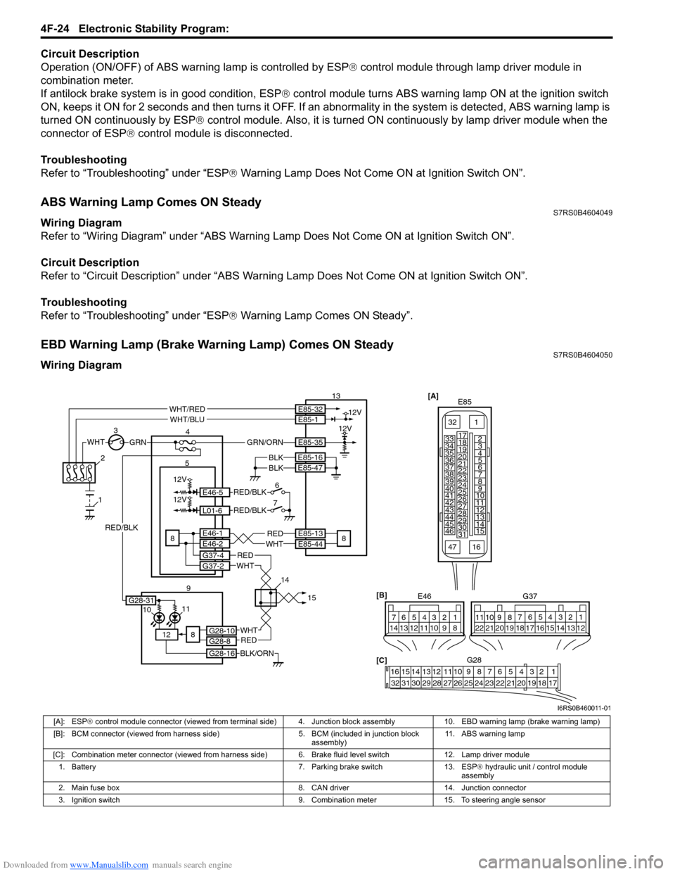
EBD Warning Lamp (Brake Warning Lamp) Comes ON SteadyS7RS0B4604050
Wiring Diagram
[A]
E85
161
15
2
3
4
5
6
7
8
9
10
11
12
13
14
17
18
19
20
21
22
23
24
25
26
27
28
29
30
31
3233
34
35
36
37
38
39
40
41
42
43
44
45
46
47WHTGRN
3
E85-13
E85-44REDWHT8 5E46-1E46-2
4
13
8
E85-16
E85-47BLKBLK
1110
12
BLK/ORN
REDWHT
REDWHT
G37-4G37-2
G28-10G28-8
G28-16
12V
12VE85-32E85-1
E85-35
WHT/REDWHT/BLU
GRN/ORN
8
2
1
9 1415
[B]
G37
E46
124
53
67
891011121314124
53
67
891011
1213141516171819202122
[C] G28
12345678910111213141516
17181920212223242526272829303132
12V
12V
6
7E46-5
L01-6
RED/BLK
RED/BLK
G28-31
RED/BLK
I6RS0B460011-01
[A]: ESP ® control module connector (viewed from terminal side) 4. Junction block assembly 10. EBD warning lamp (brake warning lamp)
[B]: BCM connector (viewed from harness side) 5. BCM (included in junction block
assembly) 11. ABS warning lamp
[C]: Combination meter connector (viewed from harness side) 6. Brake fluid level switch 12. Lamp driver module 1. Battery 7. Parking brake switch 13. ESP ® hydraulic unit / control module
assembly
2. Main fuse box 8. CAN driver 14. Junction connector
3. Ignition switch 9. Combination meter 15. To steering angle sensor
Page 600 of 1496
![SUZUKI SWIFT 2008 2.G Service Owners Manual Downloaded from www.Manualslib.com manuals search engine 4F-26 Electronic Stability Program:
Serial Data Link Circuit CheckS7RS0B4604012
Wiring Diagram
Inspection
[A]E85
161
15
2
3
4
5
6
7
8
9
10
11](/img/20/7607/w960_7607-599.png "SUZUKI SWIFT 2008 2.G Service Owners Manual Downloaded from www.Manualslib.com manuals search engine 4F-26 Electronic Stability Program:
Serial Data Link Circuit CheckS7RS0B4604012
Wiring Diagram
Inspection
[A]E85
161
15
2
3
4
5
6
7
8
9
10
11")
Downloaded from www.Manualslib.com manuals search engine 4F-26 Electronic Stability Program:
Serial Data Link Circuit CheckS7RS0B4604012
Wiring Diagram
Inspection
[A]E85
161
15
2
3
4
5
6
7
8
9
10
11
12
13
14
17
18
19
20
21
22
23
24
25
26
27
28
29
30
31
3233
34
35
36
37
38
39
40
41
42
43
44
45
46
47WHTGRN
3
E85-13REDWHT6 5E46-1E46-2
4
10
6
E85-16
E85-47BLKBLK
8
9
BLK/ORN
REDWHT
REDWHT
G37-4G37-2
G28-10G28-8
G28-16
G28-31
12V
12VE85-32E85-1
E85-35
WHT/REDWHT/BLU
GRN/ORN
6
2
1
7 1415 [B]
G37
E46
124
53
67
891011121314124
53
67
891011
1213141516171819202122
[C] G28
12345678910111213141516
17181920212223242526272829303132
12V
11
PPL/WHT
PPL/WHT
E85-33
E85-44
12
13
WHTWHT/REDB
G G1
RED/BLK
I6RS0B460012-01
[A]: ESP
® control module connector (viewed
from terminal side) 4. Junction block assembly 10. ESP
® hydraulic unit / control module assembly
[B]: BCM connector (viewed from harness side) 5. BCM (included in junction block
assembly) 11. Data link connector (DLC)
[C]: Combination meter connector (viewed from harness side) 6. CAN driver 12. To SDM
1. Battery 7. Combination meter 13. To ECM and P/S control module
2. Main fuse box 8. ESP ® warning lamp 14. Junction connector
3. Ignition switch 9. Lamp driver module 15. To steering angle sensor
Step Action YesNo
1 Check ESP ® warning lamp
1) Turn ignition switch to ON position.
Does ESP
® warning lamp come ON? Go to Step 2. Go to Step 6.
2 Check fuse
1) Turn ignition switch to OFF position.
Are main fuses for good condition? Go to Step 3. Replace fuse and check
for short.
3 Check ESP ® control module power supply circuit
1) Disconnect ESP ® control module connector.
2) Check for proper connection to ESP ® control module
connector at terminal “E85-35”.
3) If OK, then turn ignition switch to ON position and measure voltage between terminal “E85-35” and vehicle
body ground.
Is it 10 – 14 V? Go to Step 4.
“GRN/ORN” wire circuit
open.
Page 623 of 1496
Downloaded from www.Manualslib.com manuals search engine Electronic Stability Program: 4F-49
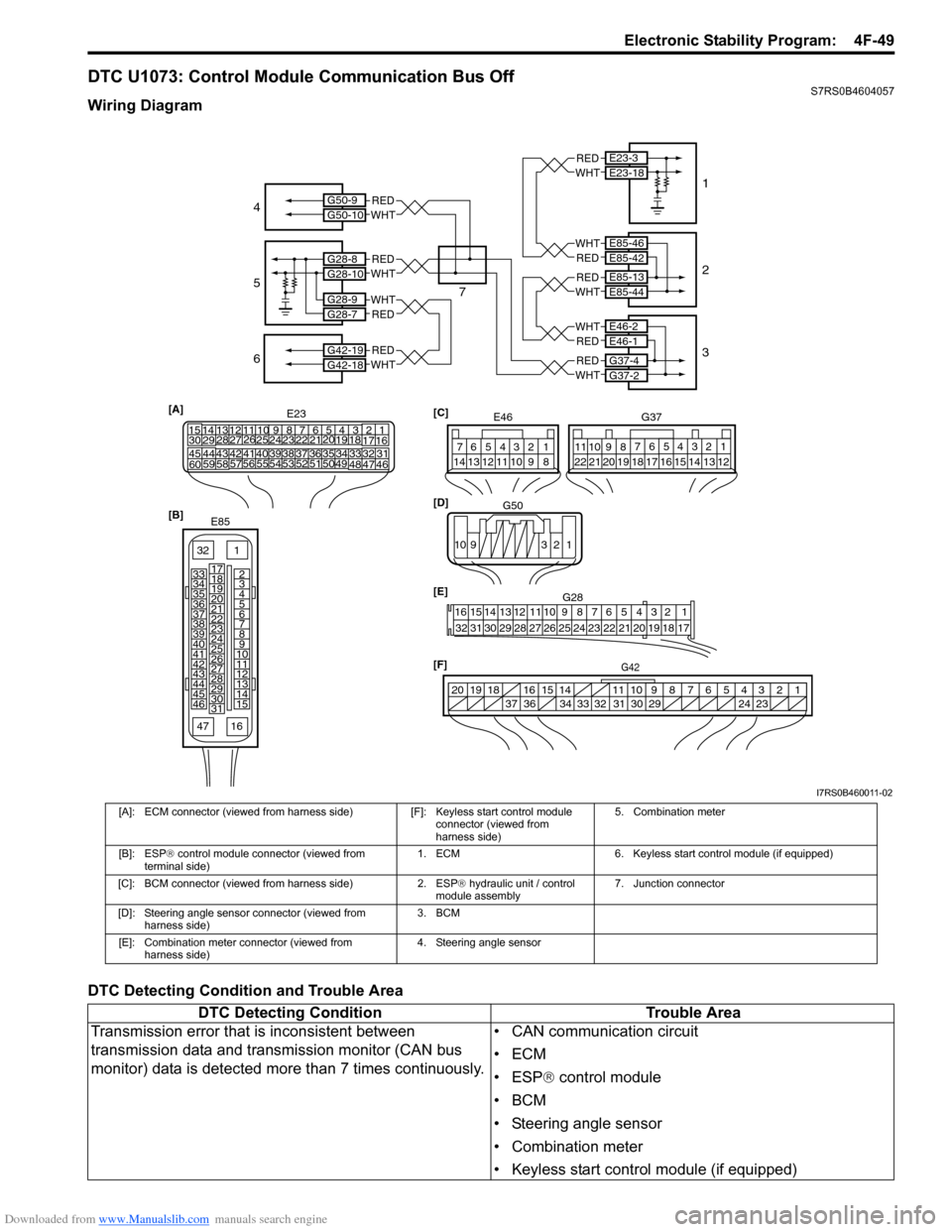
DTC U1073: Control Module Communication Bus OffS7RS0B4604057
Wiring Diagram
DTC Detecting Condition and Trouble Area
E85-13E85-44
E46-2E46-1
G37-4G37-2
E85-46E85-42
E23-3E23-18
G50-9G50-10
G28-8G28-10
G28-9G28-7
G42-19G42-18
REDWHT
WHTRED
WHTRED
REDWHT
REDWHT
WHTRED
REDWHT
REDWHT
REDWHT
[A]
21
E2334
1819
5671011
17
20
47 46
495051
2122
52 16
25 9
24
14
29
5557 54 53
59
60 5826
27
28
15
30
56 4832 31343536374042 39 38
44
45 43 41 33
1213
238
G42[F]
1234567891011
141516
36 34 33 32 31 30 29 24 23
37
181920
[B]
E85
161
15
2
3
4
5
6
7
8
9
10
11
12
13
14
17
18
19
20
21
22
23
24
25
26
27
28
29
30
31
3233
34
35
36
37
38
39
40
41
42
43
44
45
46
47 [C]
G37
E46
124
53
67
891011121314124
53
67
891011
1213141516171819202122
[E] G28
12345678910111213141516
17181920212223242526272829303132
[D] G50
109 321
4
5
7 1
2
3
6
I7RS0B460011-02
[A]: ECM connector (viewed from harness side) [F]: Keyless start control module
connector (viewed from
harness side) 5. Combination meter
[B]: ESP ® control module connector (viewed from
terminal side) 1. ECM
6. Keyless start control module (if equipped)
[C]: BCM connector (viewed from harness side) 2. ESP® hydraulic unit / control
module assembly 7. Junction connector
[D]: Steering angle sensor connector (viewed from harness side) 3. BCM
[E]: Combination meter connector (viewed from harness side) 4. Steering angle sensor
DTC Detecting Condition
Trouble Area
Transmission error that is inconsistent between
transmission data and transmission monitor (CAN bus
monitor) data is detected more than 7 times continuously. • CAN communication circuit
•ECM
• ESP
® control module
•BCM
• Steering angle sensor
• Combination meter
• Keyless start control module (if equipped)
Page 713 of 1496
Downloaded from www.Manualslib.com manuals search engine Automatic Transmission/Transaxle: 5A-69
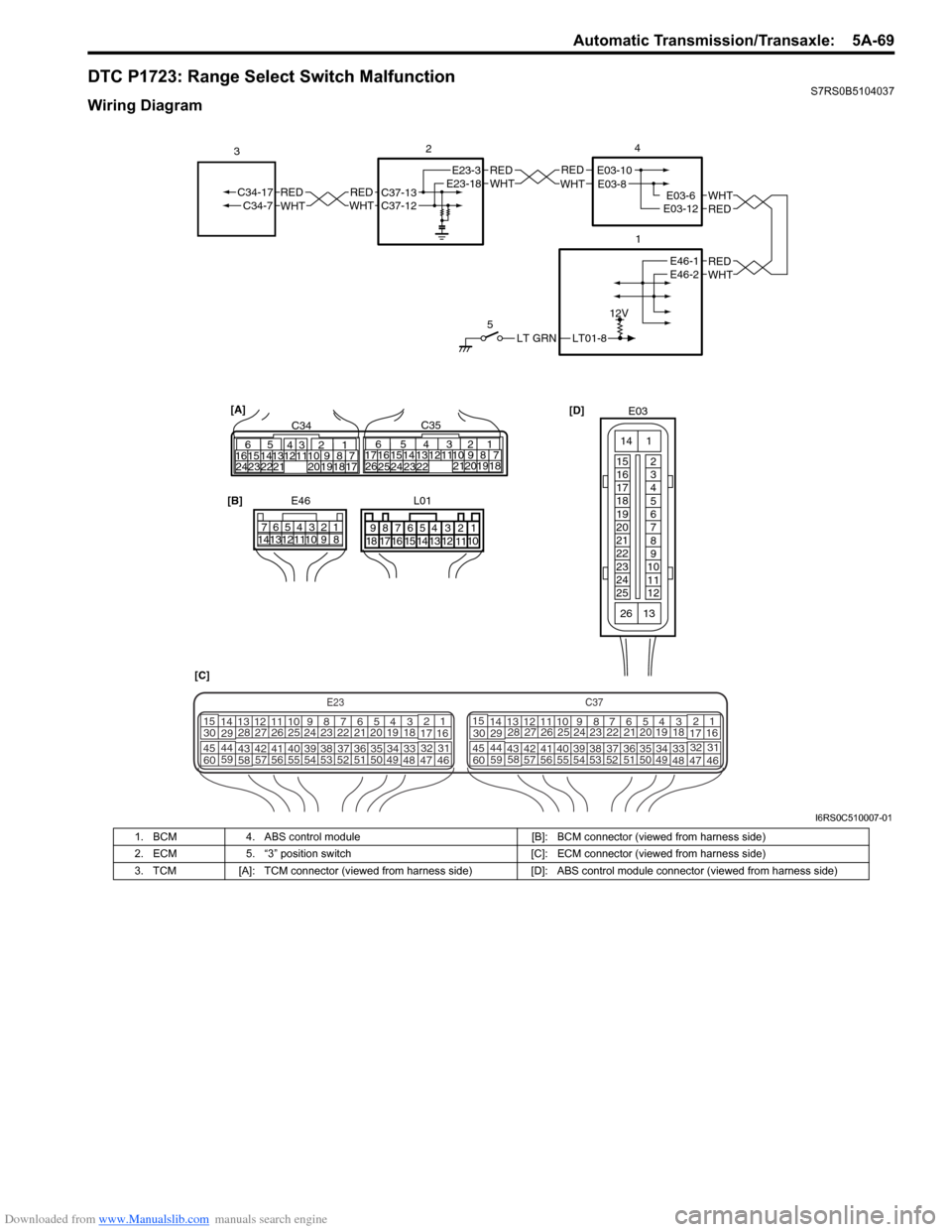
DTC P1723: Range Select Switch MalfunctionS7RS0B5104037
Wiring Diagram
LT01-8
12V
LT GRN
5
REDWHTE03-6E03-12
1
2
REDWHT
4
[D]
[C] [B]
E46
1234567
891011121314
REDWHTC37-13C37-12REDWHTC34-17C34-7
3
32
1110 9
212019 87
18
165
1615 14131211 43
2423 2122 10 9 8 7
21
1920 1817
C3417 16
26 2515 14
654
13 12
23 2224 C35
[A]
E23-3E23-18REDWHTE03-10E03-8
REDWHTE46-1E46-2
E03
15
16
17
18
19
20
21
22
23
24
25 2
3
4
5
6
7
8
9
10
11
12
1
13
14
26
E23C37
34
1819
567
1011
17
20
47 46
495051
2122
52 16
25 9
24
14
29
5557 54 53
59
60 58 2
262728
15
30
56 4832 31
34353637
4042 39 38
44
45 43 41 33 1
1213
238
34
1819
567
1011
17
20
47 46
495051
2122
52 16
25 9
24
14
29
5557 54 53
59
60 58 2
262728
15
30
56 4832 31
34353637
4042 39 38
44
45 43 41 331
1213
238
L01
678
9 54321
15161718 14 13 12 1110
I6RS0C510007-01
1. BCM
4. ABS control module [B]: BCM connector (viewed from harness side)
2. ECM 5. “3” position switch [C]: ECM connector (viewed from harness side)
3. TCM [A]: TCM connector (viewed from harness side) [D]: ABS control module connector (viewed from harness side)
Page 715 of 1496
Downloaded from www.Manualslib.com manuals search engine Automatic Transmission/Transaxle: 5A-71
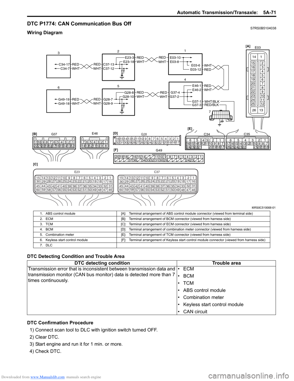
DTC P1774: CAN Communication Bus OffS7RS0B5104038
Wiring Diagram
DTC Detecting Condition and Trouble Area
DTC Confirmation Procedure1) Connect scan tool to DLC with ignition switch turned OFF.
2) Clear DTC.
3) Start engine and run it for 1 min. or more.
4) Check DTC.
REDWHTE03-6E03-12
1
4
7
REDWHT
2
[C]
[B]
G37E46
1234567
1234567
891011
891011
121314 121314
151617
18
19202122 [E]65
1615 14131211 43
2423 2122 10 9 8 7
21
1920 1817
C3417 16
26 2515 14
65 3
42
13 12
23 2224 1110 9
212019 87
18
1
C35
[F]
REDWHTC37-13C37-12REDWHTC34-17C34-7
3
1234567891011
141516
36 34 33 32 31 30 29 24 23
37
181920
[D] [A]
G49
E23-3E23-18
5
REDWHTG28-7G28-9REDWHTG49-19G49-18
6
REDWHTE03-10E03-8
G37-4G37-2
REDWHTE46-1E46-2REDWHTREDWHTG28-8G28-10
RED/BLKWHT/BLKG37-3G37-1
E03
15
16
17
18
19
20
21
22
23
24
25 2
3
4
5
6
7
8
9
10
11
12
1
13
14
26
E23C37
34
1819
567
1011
17
20
47 46
495051
2122
52 16
25 9
24
14
29
5557 54 53
59
60 58 2
262728
15
30
56 4832 31
34353637
4042 39 38
44
45 43 41 33 1
1213
238
34
1819
567
1011
17
20
47 46
495051
2122
52 16
25 9
24
14
29
5557 54 53
59
60 58 2
262728
15
30
56 4832 31
34353637
4042 39 38
44
45 43 41 331
1213
238
G281234567
8
910111213141516
1718
19
20
212223242526272829303132
I6RS0C510008-01
1. ABS control module [A]: Terminal arrangement of ABS control module connector (viewed from terminal side)
2. ECM [B]: Terminal arrangement of BCM connector (viewed from harness side)
3. TCM [C]: Terminal arrangement of ECM connector (viewed from harness side)
4. BCM [D]: Terminal arrangement of combination meter connector (viewed from harness side)
5. Combination meter [E]: Terminal arrangement of TCM connector (viewed from harness side)
6. Keyless start control module [F]: Terminal arrangement of Keyless start control module connector (viewed from harness side)
7. DLC
DTC detecting condition Trouble area
Transmission error that is incons istent between transmission data and
transmission monitor (CAN bus monitor) data is detected more than 7
times continuously. •ECM
•BCM
•TCM
• ABS control module
• Combination meter
• Keyless start control module
• CAN circuit
Page 749 of 1496

Downloaded from www.Manualslib.com manuals search engine Automatic Transmission/Transaxle: 5A-105
Automatic Transaxle Unit ComponentsS7RS0B5106030
I4RS0A510035-01
1. Drive plate4. Torque converter7. Transaxle and engine fastening nut
2. Drive plate bolt : Apply sealant 99000-31230 to thread. 5. Transaxle stiffener bolt
: Tightening torque
3. Drive plate to torque converter bolt 6. Transaxle and engine fastening bolt
Page 753 of 1496
Downloaded from www.Manualslib.com manuals search engine A u to m a tic Tra n s m is s io n /Tra n s a x le : 5 A -1 0 9
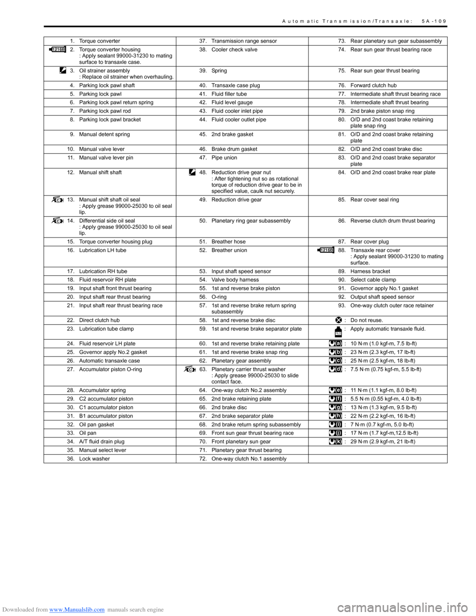
1. Torque converter37. Transmission range sensor 73. Rear planetary sun gear subassembly
2. Torque converter housing : Apply sealant 99000-31230 to mating
surface to transaxle case. 38. Cooler check valve
74. Rear sun gear thrust bearing race
3. Oil strainer assembly : Replace oil strainer when overhauling. 39. Spring
75. Rear sun gear thrust bearing
4. Parking lock pawl shaft 40. Transaxle case plug 76. Forward clutch hub
5. Parking lock pawl 41. Fluid filler tube 77. Intermediate shaft thrust bearing race
6. Parking lock pawl return spring 42. Fluid level gauge 78. Intermediate shaft thrust bearing
7. Parking lock pawl rod 43. Fluid cooler inlet pipe 79. 2nd brake piston snap ring
8. Parking lock pawl bracket 44. Fluid cooler outlet pipe 80. O/D and 2nd coast brake retaining
plate snap ring
9. Manual detent spring 45. 2nd brake gasket 81. O/D and 2nd coast brake retaining
plate
10. Manual valve lever 46. Brake drum gasket 82. O/D and 2nd coast brake disc
11. Manual valve lever pin 47. Pipe union 83. O/D and 2nd coast brake separator
plate
12. Manual shift shaft 48. Reduction drive gear nut
: After tightening nut so as rotational
torque of reduction drive gear to be in
specified value, caulk nut securely. 84. O/D and 2nd coast brake rear plate
13. Manual shift shaft oil seal : Apply grease 99000-25030 to oil seal
lip. 49. Reduction drive gear
85. Rear cover seal ring
14. Differential side oil seal : Apply grease 99000-25030 to oil seal
lip. 50. Planetary ring gear subassembly
86. Reverse clutch drum thrust bearing
15. Torque converter housing plug 51. Breather hose 87. Rear cover plug
16. Lubrication LH tube 52. Breather union 88. Transaxle rear cover
: Apply sealant 99000-31230 to mating
surface.
17. Lubrication RH tube 53. Input shaft speed sensor 89. Harness bracket
18. Fluid reservoir RH plate 54. Valve body harness 90. Select cable clamp
19. Input shaft front thrust bearing 55. 1st and reverse brake piston 91. Governor apply No.1 gasket
20. Input shaft rear thrust bearing 56. O-ring 92. Output shaft speed sensor
21. Input shaft rear thrust bearing race 57. 1st and reverse brake return spring
subassembly 93. One-way clutch outer race retainer
22. Direct clutch hub 58. 1st and reverse brake disc : Do not reuse.
23. Lubrication tube clamp 59. 1st and reverse brake separator plate : Apply automatic transaxle fluid.
24. Fluid reservoir LH plate 60. 1st and reverse brake retaining plate : 10 N⋅m (1.0 kgf-m, 7.5 lb-ft)
25. Governor apply No.2 gasket 61. 1st and reverse brake snap ring : 23 N⋅m (2.3 kgf-m, 17 lb-ft)
26. Automatic transaxle case 62. Planetary gear assembly : 25 N⋅m (2.5 kgf-m, 18 lb-ft)
27. Accumulator piston O-ring 63. Planetary carrier thrust washer
: Apply grease 99000-25030 to slide
contact face. : 7.5 N
⋅m (0.75 kgf-m, 5.5 lb-ft)
28. Accumulator spring 64. One-way clutch No.2 assembly : 11 N⋅m (1.1 kgf-m, 8.0 lb-ft)
29. C2 accumulator piston 65. 2nd brake retaining plate : 5.5 N⋅m (0.55 kgf-m, 4.0 lb-ft)
30. C1 accumulator piston 66. 2nd brake disc : 13 N⋅m (1.3 kgf-m, 9.5 lb-ft)
31. B1 accumulator piston 67. 2nd brake separator plate : 22 N⋅m (2.2 kgf-m, 16 lb-ft)
32. Oil pan gasket 68. 2nd brake return spring subassembly : 7 N⋅m (0.7 kgf-m, 5.0 lb-ft)
33. Oil pan 69. Front sun gear thrust bearing race : 17 N⋅m (1.7 kgf-m,12.5 lb-ft)
34. A/T fluid drain plug 70. Front planetary sun gear : 29 N⋅m (2.9 kgf-m, 21 lb-ft)
35. Manual select lever 71. Planetary gear thrust bearing
36. Lock washer 72. One-way clutch No.1 assembly
Page 767 of 1496
Downloaded from www.Manualslib.com manuals search engine Automatic Transmission/Transaxle: 5A-123
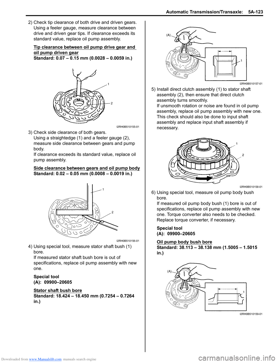
2) Check tip clearance of both drive and driven gears.Using a feeler gauge, m easure clearance between
drive and driven gear tips. If clearance exceeds its
standard value, replace oil pump assembly.
Tip clearance between oil pump drive gear and
oil pump driven gear
Standard: 0.07 – 0.15 mm (0.0028 – 0.0059 in.)
3) Check side clearance of both gears. Using a straightedge (1) and a feeler gauge (2),
measure side clearance between gears and pump
body.
If clearance exceeds its standard value, replace oil
pump assembly.
Side clearance between gears and oil pump body
Standard: 0.02 – 0.05 mm (0.0008 – 0.0019 in.)
4) Using special tool, measure stator shaft bush (1) bore.
If measured stator shaft bush bore is out of
specifications, replace oil pump assembly with new
one.
Special tool
(A): 09900–20605
Stator shaft bush bore
Standard: 18.424 – 18.450 mm (0.7254 – 0.7264
in.) 5) Install direct clutch asse
mbly (1) to stator shaft
assembly (2), then ensure that direct clutch
assembly turns smoothly.
If unsmooth rotation or noise are found in oil pump
assembly, replace oil pump assembly with new one.
This check should also be done to input shaft
assembly and replace input shaft assembly if
necessary.
6) Using special tool, measure oil pump body bush bore.
If measured oil pump body bush (1) bore is out of
specifications, replace o il pump assembly with new
one. Torque converter also needs to be checked.
Replace torque converter, if necessary.
Special tool
(A): 09900–20605
Oil pump body bush bore
Standard: 38.113 – 38.138 mm (1.5005 – 1.5015
in.)
I2RH0B510155-01
I2RH0B510156-01
I2RH0B510157-01
I2RH0B510158-01
I2RH0B510159-01