Lower control arm SUZUKI SWIFT 2008 2.G Service Owner's Manual
[x] Cancel search | Manufacturer: SUZUKI, Model Year: 2008, Model line: SWIFT, Model: SUZUKI SWIFT 2008 2.GPages: 1496, PDF Size: 34.44 MB
Page 871 of 1496

Downloaded from www.Manualslib.com manuals search engine Steering General Diagnosis: 6A-2
Diagnostic Information and Procedures
Steering Symptom DiagnosisS7RS0B6104001
ConditionPossible cause Correction / Reference Item
Hard steering Tire not adequately inflated Inflate tires to proper pressure.
Malfunction of power steering system Check and correct.
Bind in tie-rod end ball studs or lower
ball joints Replace tie-rod end or front suspension arm.
Disturbed front wheel alignment Check and adjust front wheel alignment.
Bind in steering column Repair or replace steering column.
Rack and pinion adjustment Check and adjustment rack and pinion torque.
Too much play in steering Wheel bearings worn Replace wheel bearing.
Loose steering gear case bolts Tighten gear case bolts.
Faulty steering gear case assembly Replace steering gear case assembly.
Worn steering shaft joints Replace joint.
Worn tie-rod ends or tie-rod inside ball
joints Replace tie-rod end or tie-rod.
Worn lower ball joints Replace front suspension control arm.
Rack and pinion adjustment Check and adjustment rack and pinion torque.
Poor return ability Bind in tie-rod end ball studs Replace tie-rod end.
Bind in ball joints Replace front suspension control arm.
Bind in steering column Repair or replace steering column.
Disturbed front end alignment Check and adjust front end alignment.
Faulty steering gear case assembly Replace steering gear case assembly.
Tires not adequately inflated Adjust tire pressure.
Rack and pinion adjustment Check and adjustment rack and pinion torque.
Rack and pinion noise
(Rattle or chuckle) Loose steering gear case bolts
Tighten steering gear case bolts.
Rack and pinion adjustment Check and adjustment rack and pinion torque.
Faulty steering gear case assembly Replace steering gear case assembly.
Broken or other wise damaged wheel
bearing(s) Replace wheel bearing(s).
Wander or poor steering
stability Mismatched or uneven tires
Replace or inflate tires to proper pressure.
Loosen ball joints and tie-rod ends Replace suspension control arm or tie-rod end.
Faulty struts or mountings Replace strut or repair mounting.
Loose stabilizer bar Tighten or replace stabilizer bar or bush.
Broken or sagging springs Replace spring.
Rack and pinion adjustment Check and adjustment rack and pinion torque.
Disturbed front wheel alignment Check and adjust front wheel alignment.
Faulty steering gear case assembly Replace steering gear case assembly.
Erratic steering when
braking Worn wheel bearing(s)
Replace wheel bearing(s).
Broken or sagging spring(s) Replace coil spring(s).
Wheel tires are inflated unequally Inflate tires to proper pressure.
Disturbed front wheel alignment Check and adjust front wheel alignment.
Brakes not working in unison Check and repair brake system.
Leaking caliper Repair or replace caliper.
Warped discs Replace brake disc.
Badly worn brake pads Replace brake pads.
Page 994 of 1496

Downloaded from www.Manualslib.com manuals search engine 7B-46 Air Conditioning System: Automatic Type
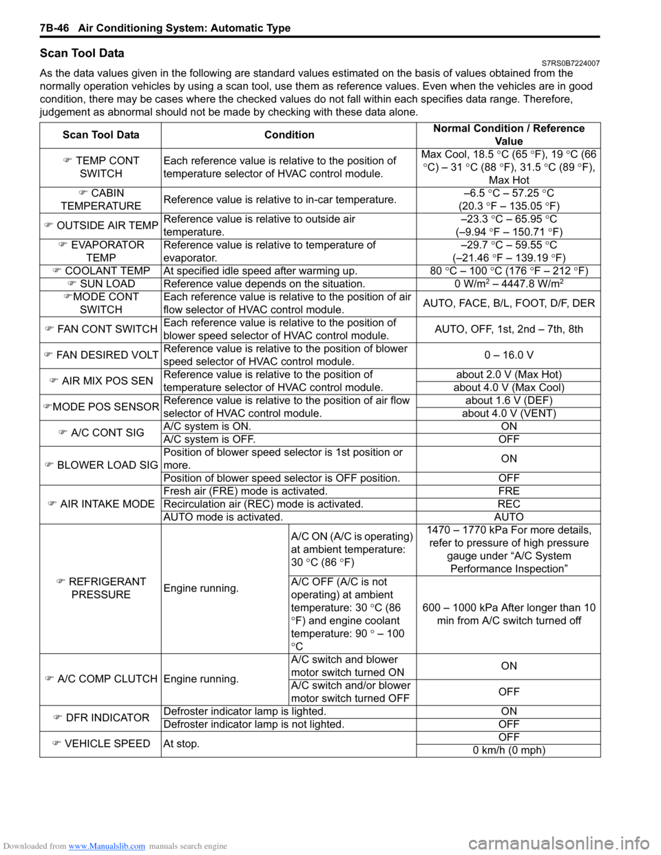
Scan Tool DataS7RS0B7224007
As the data values given in the following are standard values estimated on the basis of values obtained from the
normally operation vehicles by using a scan tool, use them as reference values. Even when the vehicles are in good
condition, there may be cases where the checked values do not fall within each specifies data range. Therefore,
judgement as abnormal should not be ma de by checking with these data alone.
Scan Tool Data Condition Normal Condition / Reference
Va l u e
�) TEMP CONT
SWITCH Each reference value is relative to the position of
temperature selector of HVAC control module. Max Cool, 18.5
°C (65 ° F), 19 °C (66
° C) – 31 °C (88 °F), 31.5 °C (89 °F),
Max Hot
�) CABIN
TEMPERATURE Reference value is relative to in-car temperature. –6.5
°C – 57.25 ° C
(20.3 °F – 135.05 °F)
�) OUTSIDE AIR TEMP Reference value is relative to outside air
temperature. –23.3
°C – 65.95 °C
(–9.94 °F – 150.71 °F)
�) EVAPORATOR
TEMP Reference value is relative to temperature of
evaporator. –29.7
°C – 59.55 °C
(–21.46 °F – 139.19 °F)
�) COOLANT TEMP At specified id le speed after warming up. 80 °C – 100 °C (176 ° F – 212 ° F)
�) SUN LOAD Reference value depends on the situation. 0 W/m
2 – 4447.8 W/m2
�)MODE CONT
SWITCH Each reference value is relative to the position of air
flow selector of HVAC control module.
AUTO, FACE, B/L, FOOT, D/F, DER
�) FAN CONT SWITCH Each reference value is relative to the position of
blower speed selector of HVAC control module. AUTO, OFF, 1st, 2nd – 7th, 8th
�) FAN DESIRED VOLT Reference value is relative to the position of blower
speed selector of HVAC control module. 0 – 16.0 V
�) AIR MIX POS SEN Reference value is relative to the position of
temperature selector of HVAC control module. about 2.0 V (Max Hot)
about 4.0 V (Max Cool)
�) MODE POS SENSOR Reference value is relative to the position of air flow
selector of HVAC control module. about 1.6 V (DEF)
about 4.0 V (VENT)
�) A/C CONT SIG A/C system is ON. ON
A/C system is OFF. OFF
�) BLOWER LOAD SIG Position of blower speed selector is 1st position or
more.
ON
Position of blower speed selector is OFF position. OFF
�) AIR INTAKE MODE Fresh air (FRE) mode is activated. FRE
Recirculation air (REC) mode is activated. REC
AUTO mode is activated. AUTO
�) REFRIGERANT
PRESSURE Engine running. A/C ON (A/C is operating)
at ambient temperature:
30
°C (86 °F) 1470 – 1770 kPa For more details,
refer to pressure of high pressure
gauge under “A/C System Performance Inspection”
A/C OFF (A/C is not
operating) at ambient
temperature: 30 °C (86
° F) and engine coolant
temperature: 90 ° – 100
° C 600 – 1000 kPa After longer than 10
min from A/C switch turned off
�) A/C COMP CLUTCH Engine running. A/C switch and blower
motor switch turned ON
ON
A/C switch and/or blower
motor switch turned OFF OFF
�) DFR INDICATOR Defroster indicator
lamp is lighted. ON
Defroster indicator la mp is not lighted. OFF
�) VEHICLE SPEED At stop. OFF
0 km/h (0 mph)
Page 1415 of 1496

Downloaded from www.Manualslib.com manuals search engine Body Electrical Control System: 10B-12
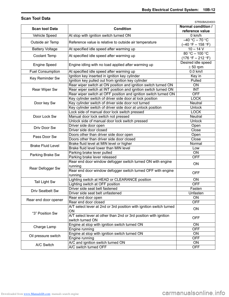
Scan Tool DataS7RS0BA204003
Scan tool DataConditionNormal condition /
reference value
Vehicle Speed At stop with ignition switch turned ON 0 km/h
Outside air Temp Reference value is relative to outside air temperature –40
°C – 70 °C
(–40 °F – 158 ° F)
Battery Voltage At specified idle speed after warming up 10 – 14 V
Coolant Temp At specified idle speed after warming up 80
°C – 100 ° C
(176 °F – 212 ° F)
Engine Speed Engine idling with no load applied after warming up Desired idle speed
± 50 rpm
Fuel Consumption At specified idle speed after warming up 0.0 km/l
Key Reminder Sw Ignition key inserted in
ignition key cylinder Key in
Ignition key pulled out from ignition key cylinder Pulled
Rear Wiper Sw Rear wiper switch at ON position and ignition switch turned ON
ON
Rear wiper switch at INT position and ignition switch turned ON INT
Rear wiper switch at OFF position and ignition switch turned ON OFF
Door key Sw Key cylinder switch of driver side door at lock position
LOCK
Key cylinder switch of driver side door not turned Neutral
Key cylinder switch of driver side door at unlock position Unlock
Door Lock Sw Lock side of manual door lock switch pressed
LOCK
Manual door lock switch not pressed Neutral
Unlock side of manual door lock switch pressed Unlock
Driv Door Sw Driver side door open
Open
Driver side door closed Close
Pass Door Sw Doors other than driver side door open
Open
Doors other than driver side door closed Close
Brake Fluid Level Brake fluid level at MIN level or higher
Normal
Brake fluid level lower than MIN level Low
Parking Brake Sw Parking brake lever pulled
ON
Parking brake lever released OFF
Rear Defogger Sw Rear end door window defogger switch turned ON with engine
running
ON
Rear end door window defogger switch turned OFF with engine
running OFF
Tail Light Sw Lighting switch at HEAD
or CLEARANCE position ON
Lighting switch at OFF position OFF
Driv Seatbelt Sw Driver side seat belt fastened
Fasten
Driver side seat belt unfastened Unfasten
Rear end door opener Rear end door open
ON
Rear end door closed OFF
“3” Position Sw A/T select lever at 2nd or 3rd position with ignition switch turned
ON
ON
A/T select lever at other than 2nd or 3rd position with ignition
switch turned ON OFF
Charge Lamp Engine at stop with ignition switch turned ON
ON
Engine running OFF
Oil pressure switch Engine at stop with ignition switch turned ON
ON
Engine running OFF
A/C Switch A/C and ignition switch turned ON
ON
A/C switch turned OFF OFF
Page 1416 of 1496

Downloaded from www.Manualslib.com manuals search engine 10B-13 Body Electrical Control System:
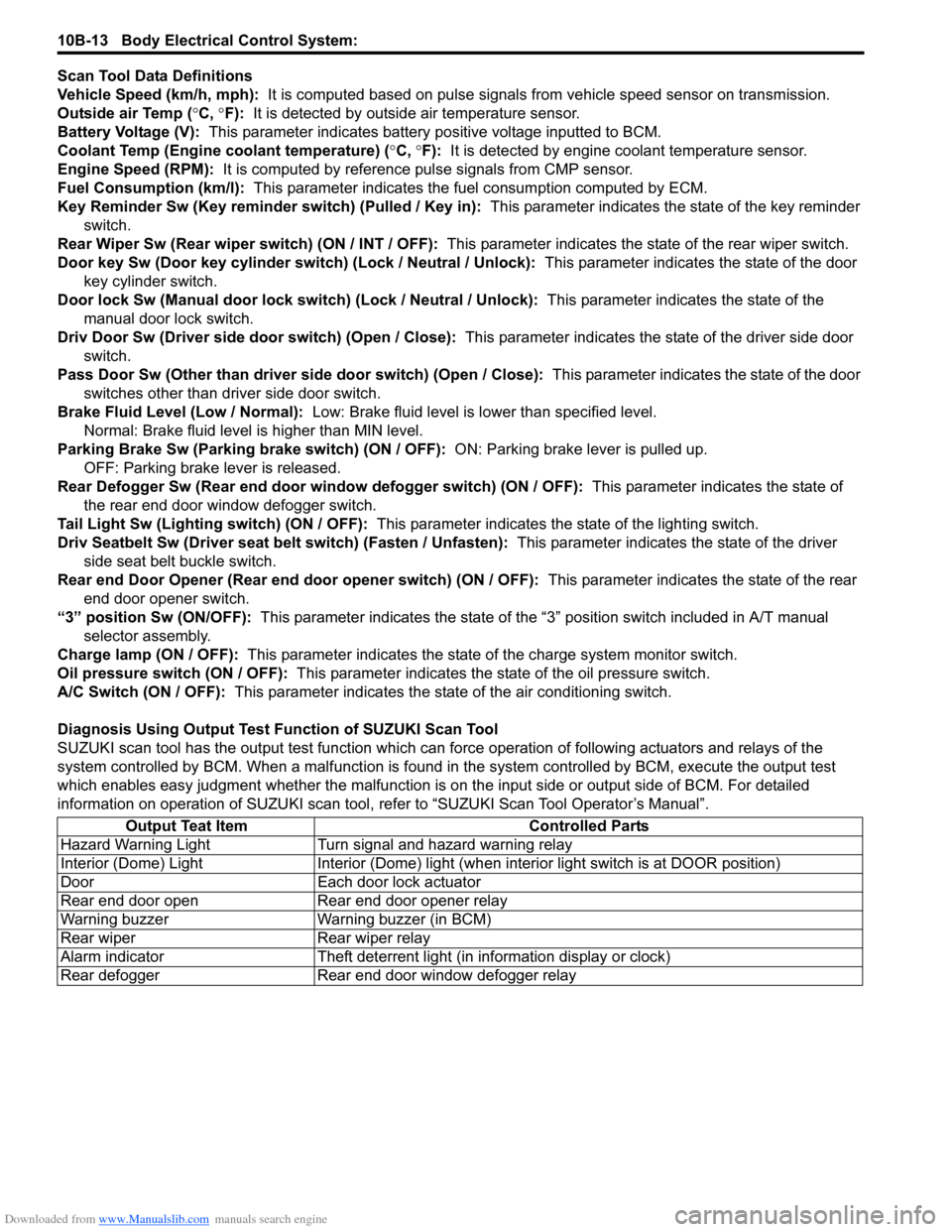
Scan Tool Data Definitions
Vehicle Speed (km/h, mph): It is computed based on pulse signals from vehicle speed sensor on transmission.
Outside air Temp ( °C, °F): It is detected by outside air temperature sensor.
Battery Voltage (V): This parameter indicates battery po sitive voltage inputted to BCM.
Coolant Temp (Engine coolant temperature) ( °C, °F): It is detected by engine coolant temperature sensor.
Engine Speed (RPM): It is computed by reference pulse signals from CMP sensor.
Fuel Consumption (km/l): This parameter indicates the fuel consumption computed by ECM.
Key Reminder Sw (Key reminder switch) (Pulled / Key in): This parameter indicates the state of the key reminder
switch.
Rear Wiper Sw (Rear wiper switch) (ON / INT / OFF): This parameter indicates the state of the rear wiper switch.
Door key Sw (Door key cylinder switch) (Lock / Neutral / Unlock): This parameter indicates the state of the door
key cylinder switch.
Door lock Sw (Manual door lock switch) (Lock / Neutral / Unlock): This parameter indicates the state of the
manual door lock switch.
Driv Door Sw (Driver side d oor switch) (Open / Close): This parameter indicates the state of the driver side door
switch.
Pass Door Sw (Other than driver side door switch) (Open / Close): This parameter indicates the state of the door
switches other than driver side door switch.
Brake Fluid Level (Low / Normal): Low: Brake fluid level is lower than specified level.
Normal: Brake fluid level is higher than MIN level.
Parking Brake Sw (Parking brake switch) (ON / OFF): ON: Parking brake lever is pulled up.
OFF: Parking brake lever is released.
Rear Defogger Sw (Rear end door window defogger switch) (ON / OFF): This parameter indicates the state of
the rear end door window defogger switch.
Tail Light Sw (Lighting switch) (ON / OFF): This parameter indicates the state of the lighting switch.
Driv Seatbelt Sw (Driver seat belt switch) (Fasten / Unfasten): This parameter indicates the state of the driver
side seat belt buckle switch.
Rear end Door Opener (Rear end door opener switch) (ON / OFF): This parameter indicates the state of the rear
end door opener switch.
“3” position Sw (ON/OFF): This parameter indicates the state of the “3 ” position switch included in A/T manual
selector assembly.
Charge lamp (ON / OFF): This parameter indicates the state of the charge system monitor switch.
Oil pressure switch (ON / OFF): This parameter indicates the state of the oil pressure switch.
A/C Switch (ON / OFF): This parameter indicates the state of the air conditioning switch.
Diagnosis Using Output Test Function of SUZUKI Scan Tool
SUZUKI scan tool has the output test function which can force operation of following actuators and relays of the
system controlled by BCM. When a malf unction is found in the system controlled by BCM, execute the output test
which enables easy judgment whether the malfunction is on the input side or output side of BCM. For detailed
information on operation of SUZUKI scan tool, refer to “SUZUKI Scan Tool Operator’s Manual”.
Output Teat Item Controlled Parts
Hazard Warning Light Turn signal and hazard warning relay
Interior (Dome) Light Interior (Dome) light (wh en interior light switch is at DOOR position)
Door Each door lock actuator
Rear end door open Rear end door opener relay
Warning buzzer Warning buzzer (in BCM)
Rear wiper Rear wiper relay
Alarm indicator Theft deterrent light (in information display or clock)
Rear defogger Rear end door window defogger relay