Torque converter SUZUKI SWIFT 2008 2.G Service Owner's Guide
[x] Cancel search | Manufacturer: SUZUKI, Model Year: 2008, Model line: SWIFT, Model: SUZUKI SWIFT 2008 2.GPages: 1496, PDF Size: 34.44 MB
Page 792 of 1496

Downloaded from www.Manualslib.com manuals search engine 5A-148 Automatic Transmission/Transaxle:
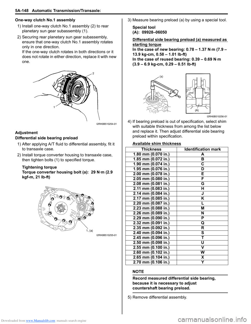
One-way clutch No.1 assembly1) Install one-way clutch No.1 assembly (2) to rear planetary sun gear subassembly (1).
2) Securing rear planetary sun gear subassembly, ensure that one-way clutch No.1 assembly rotates
only in one direction.
If the one-way clutch rotates in both directions or it
does not rotate in either direction, replace it with new
one.
Adjustment
Differential side bearing preload 1) After applying A/T fluid to differential assembly, fit it to transaxle case.
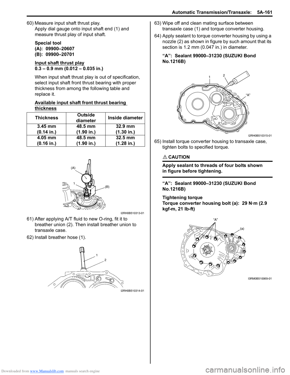
2) Install torque converter housing to transaxle case, then tighten bolts (1) to specified torque.
Tightening torque
Torque converter housing bolt (a): 29 N·m (2.9
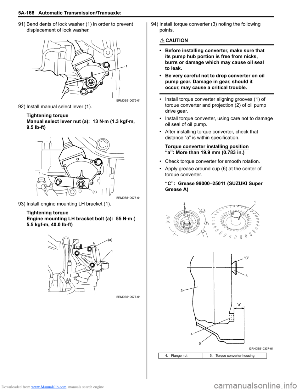
kgf-m, 21 lb-ft) 3) Measure bearing preload (a) by using a special tool.
Special tool
(A): 09928–06050
Differential side bearing preload (a) measured as
starting torque
In the case of new bearing: 0.78 – 1.37 N ⋅m (7.9 –
13.9 kg-cm, 0.58 – 1.01 lb-ft)
In the case of reused bearing: 0.39 – 0.69 N ⋅m
(3.9 – 6.9 kg-cm, 0.29 – 0.51 lb-ft)
4) If bearing preload is out of specification, select shim with suitable thickness from among the list below
and replace it. Then adjust differential side bearing
preload within specification.
Available shim thickness
NOTE
Record measured differential side bearing,
because it is necessary to adjust
countershaft bearing preload.
5) Remove differential assembly.
I2RH0B510254-01
I2RH0B510255-01
Thickness Identification mark
1.80 mm (0.070 in.) A
1.85 mm (0.072 in.) B
1.90 mm (0.074 in.) C
1.95 mm (0.076 in.) D
2.00 mm (0.078 in.) E
2.05 mm (0.080 in.) F
2.08 mm (0.081 in.) G
2.11 mm (0.083 in.) H
2.14 mm (0.084 in.) J
2.17 mm (0.085 in.) K
2.20 mm (0.087 in.) L
2.23 mm (0.088 in.) M
2.26 mm (0.089 in.) N
2.29 mm (0.090 in.) P
2.32 mm (0.091 in.) Q
2.35 mm (0.092 in.) R
2.40 mm (0.094 in.) S
2.45 mm (0.096 in.) T
2.50 mm (0.098 in.) U
2.55 mm (0.100 in.) V
2.60 mm (0.102 in.) W
2.65 mm (0.104 in.) X
2.70 mm (0.106 in.) Y
I2RH0B510256-01
Page 793 of 1496

Downloaded from www.Manualslib.com manuals search engine Automatic Transmission/Transaxle: 5A-149
Countershaft bearing preload1) After applying A/T fluid to countershaft assembly (1) and differential assembly (2), fit them.
2) Install torque converter housing to transaxle case, then tighten bolts to specified torque.
Tightening torque
Torque converter housing bolt: 29 N·m (2.9 kgf-
m, 21 lb-ft)
3) Measure bearing preload (b) by using special tool. Special tool
(A): 09928–06050
Countershaft bearing preload (b) measured as
starting torque
In the case of new bearing: 0.33 – 0.96 N⋅ m (3.3 –
9.8 kg-cm, 0.24 – 0.69 lb-ft)
In the case of reused bearing: 0.17 – 0.38 N ⋅m
(1.7 – 3.8 kg-cm, 0.12 – 0.28 lb-ft) 4) If bearing preload is out of specification, select shim
with suitable thickness from among the list below
and replace it. Then adjust countershaft bearing
preload within specification.
Available shim thickness
5) Remove differential assembly and countershaft assembly.
Countershaft bearing
preload =(b) – Differential side bearing
preload (a)
I2RH0B510257-01
I3RM0B510067-01
Thickness Identification mark
1.70 (0.066 in.) 1
1.75 (0.068 in.) 2
1.80 (0.070 in.) 3
1.85 (0.072 in.) 4
1.90 (0.074 in.) 5
1.93 (0.075 in.) 6
1.96 (0.077 in.) 7
1.99 (0.078 in.) A
2.02 (0.079 in.) B
2.05 (0.080 in.) C
2.08 (0.081 in.) D
2.11 (0.083 in.) E
2.14 (0.084 in.) F
2.17 (0.085 in.) G
2.20 (0.086 in.) H
2.25 (0.088 in.) K
2.30 (0.090 in.) L
2.35 (0.092 in.) M
2.40 (0.094 in.) N
2.45 (0.096 in.) P
2.50 (0.098 in.) Q
2.55 (0.100 in.) R
2.60 (0.102 in.) S
2.65 (0.104 in.) U
2.70 (0.106 in.) W
Page 805 of 1496

Downloaded from www.Manualslib.com manuals search engine Automatic Transmission/Transaxle: 5A-161
60) Measure input shaft thrust play.Apply dial gauge onto input shaft end (1) and
measure thrust play of input shaft.
Special tool
(A): 09900–20607
(B): 09900–20701
Input shaft thrust play
0.3 – 0.9 mm (0.012 – 0.035 in.)
When input shaft thrust play is out of specification,
select input shaft front th rust bearing with proper
thickness from among the following table and
replace it.
Available input shaft front thrust bearing
thickness
61) After applying A/T fluid to new O-ring, fit it to breather union (2). Then install breather union to
transaxle case.
62) Install breather hose (1). 63) Wipe off and clean mating surface between
transaxle case (1) and torque converter housing.
64) Apply sealant to torque converter housing by using a nozzle (2) as shown in figure by such amount that its
section is 1.2 mm (0.047 in.) in diameter.
“A”: Sealant 99000–31230 (SUZUKI Bond
No.1216B)
65) Install torque converter housing to transaxle case, tighten bolts to specified torque.
CAUTION!
Apply sealant to threads of four bolts shown
in figure before tightening.
“A”: Sealant 99000–31230 (SUZUKI Bond
No.1216B)
Tightening torque
Torque converter housing bolt (a): 29 N·m (2.9
kgf-m, 21 lb-ft)
Thickness
Outside
diameter Inside diameter
3.45 mm
(0.14 in.) 48.5 mm
(1.90 in.) 32.9 mm
(1.30 in.)
4.05 mm
(0.16 in.) 48.5 mm
(1.90 in.) 32.5 mm
(1.28 in.)
I2RH0B510313-01
I2RH0B510314-01
1 2
“A”
I2RH0B510315-01
I3RM0B510069-01
Page 810 of 1496

Downloaded from www.Manualslib.com manuals search engine 5A-166 Automatic Transmission/Transaxle:
91) Bend dents of lock washer (1) in order to prevent displacement of lock washer.
92) Install manual select lever (1). Tightening torque
Manual select lever nut (a): 13 N·m (1.3 kgf-m,
9.5 lb-ft)
93) Install engine mounting LH bracket (1). Tightening torque
Engine mounting LH bracket bolt (a): 55 N·m (
5.5 kgf-m, 40.0 lb-ft) 94) Install torque converter (3) noting the following
points.
CAUTION!
• Before installing converter, make sure that its pump hub portion is free from nicks,
burrs or damage which may cause oil seal
to leak.
• Be very careful not to drop converter on oil pump gear. Damage in gear, should it
occur, may cause a critical trouble.
• Install torque converter aligning grooves (1) of torque converter and projection (2) of oil pump
drive gear.
• Install torque converter, using care not to damage oil seal of oil pump.
• After installing torque converter, check that distance “a” is within specification.
Torque converter installing position
“a”: More than 19.9 mm (0.783 in.)
• Check torque converter for smooth rotation.
• Apply grease around cup (6) at the center of torque converter.
“C”: Grease 99000–25011 (SUZUKI Super
Grease A)
1
I3RM0B510075-01
1
(a)
I3RM0B510076-01
I3RM0B510077-01
4. Flange nut 5. Torque converter housing
I2RH0B510337-01
Page 811 of 1496

Downloaded from www.Manualslib.com manuals search engine Automatic Transmission/Transaxle: 5A-167
Specifications
Tightening Torque SpecificationsS7RS0B5107001
NOTE
The specified tightening torque is also described in the following.
“Select Cable Components”
“Automatic Transaxle Unit Components”
“Automatic Transaxle Assembly Components”
“Oil Pump Assembly Components”
“Transaxle Rear Cover (O/D and 2nd Coast Brake Piston) Assembly Components”
“Valve Body Assembly Components”
“Differential Assembly Components”
Reference:
For the tightening torque of fastener not specified in this section, refer to “Fasteners Information in Section 0A”.
Fastening part
Tightening torque
Note
N ⋅mkgf-mlb-ft
A/T fluid drain plug 171.7 12.5 �) / �) / �)
Transmission range sensor bolt 5.5 0.55 4.0�) / �)
Output shaft speed sensor bolt 131.3 9.5 �) / �)
Input shaft speed sensor bolt 5.5 0.55 4.0�)
Valve body harness connector bolt 7.00.7 5.0 �)
Shift solenoid bolt 111.1 8.0 �)
Oil strainer bolt 101.0 7.5 �) / �)
Oil pan bolt 7.00.7 5.0 �) / �)
Transaxle and engine fastening bolt and nut 85 8.5 61.5�)
Drive plate to torque converter bolt 252.5 18.0 �)
Transaxle stiffener bolt 555.5 40�)
Starter motor bolt and nut 505.0 36.5 �)
Oil pump subassembly bolt 101.0 7.5 �)
Rear cover plug 7.5 0.75 5.5�)
Solenoid valve bolt 111.1 8.0 �)
Final gear bolt 787.8 56.5 �)
Torque converter housing plug 7.5 0.75 5.5�)
Lubrication tube clamp bolt 5.5 0.55 4.0�)
Fluid reservoir RH plate bolt 5.5 0.55 4.0�)
Torque converter housing bolt 292.9 21�) / �) / �)
Manual detent spring bolt 101.0 7.5 �)
Parking lock pawl bracket bolt 7.5 0.75 5.5�)
Rear cover bolt 252.5 18.0 �)
Fluid reservoir LH plate bolt 101.0 7.5 �)
Oil pump assembly bolt 252.5 18.0 �)
Transaxle case plug 7.5 0.75 5.5�)
Valve body harness connector bolt 5.5 0.55 4.0�)
Valve body bolt 111.1 8.0 �)
Fluid outlet union 252.5 18.0 �)
Fluid cooler pipe union bolt 222.2 16.0 �)
Fluid cooler pipe bracket bolt 101.0 7.5 �)
Fluid filler tube bolt 101.0 7.5 �)
Input shaft speed sensor bolt 111.1 8.0 �)
Harness bracket bolt 232.3 17.0 �)
Select cable clamp bolt 101.0 7.5 �)
Transmission range sensor lock nut 70.7 5.0 �)
Manual select lever nut 131.3 9.5 �)
Engine mounting LH bracket bolt 555.5 40.0
�)