ecm input SUZUKI SWIFT 2008 2.G Service Owner's Guide
[x] Cancel search | Manufacturer: SUZUKI, Model Year: 2008, Model line: SWIFT, Model: SUZUKI SWIFT 2008 2.GPages: 1496, PDF Size: 34.44 MB
Page 669 of 1496
Downloaded from www.Manualslib.com manuals search engine Automatic Transmission/Transaxle: 5A-25
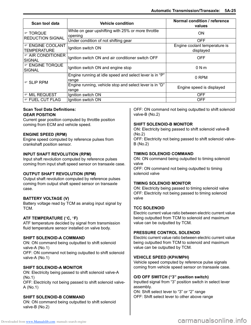
Scan Tool Data Definitions:
GEAR POSITION
Current gear position computed by throttle position
coming from ECM and vehicle speed.
ENGINE SPEED (RPM)
Engine speed computed by reference pulses from
crankshaft position sensor.
INPUT SHAFT REVOLUTION (RPM)
Input shaft revolution computed by reference pulses
coming from input shaft speed sensor on transaxle case.
OUTPUT SHAFT REVOLUTION (RPM)
Output shaft revolution computed by reference pulses
coming from output shaft speed sensor on transaxle
case.
BATTERY VOLTAGE (V)
Battery voltage read by TCM as analog input signal by
TCM.
ATF TEMPERATURE (°C, °F)
ATF temperature decided by signal from transmission
fluid temperature sensor installed on valve body.
SHIFT SOLENOID-A COMMAND
ON: ON command being outputted to shift solenoid
valve-A (No.1)
OFF: ON command not being outputted to shift solenoid
valve-A (No.1)
SHIFT SOLENOID-A MONITOR
ON: Electricity being passed to shift solenoid valve-A
(No.1)
OFF: Electricity not being passed to shift solenoid valve-
A (No.1)
SHIFT SOLENOID-B COMMAND
ON: ON command being outputted to shift solenoid
valve-B (No.2) OFF: ON command not being outputted to shift solenoid
valve-B (No.2)
SHIFT SOLENOID-B MONITOR
ON: Electricity being passed to shift solenoid valve-B
(No.2)
OFF: Electricity not being passed to shift solenoid valve-
B (No.2)
TIMING SOLENOID COMMAND
ON: ON command being outputted to timing solenoid
valve
OFF: ON command not being outputted to timing
solenoid valve
TIMING SOLENOID MONITOR
ON: Electricity being passed to timing solenoid valve
OFF: Electricity not being passed to timing solenoid
valve
TCC SOLENOID
Electric current value ratio between electric current value
being outputted from TCM to solenoid and maximum
value can be outputted by TCM.
PRESSURE CONTROL SOLENOID
Electric current value ratio between electric current value
being outputted from TCM to solenoid and maximum
value can be outputted by TCM.
VEHICLE SPEED (KPH/MPH)
Vehicle speed computed by reference pulse signals
coming from vehicle speed sensor on transaxle case.
O/D OFF SWITCH (“3” position switch)
Inputted signal from “3” position switch in select lever
assembly.
ON: Shift select lever to “3” or “2” range
OFF: Shift select lever to other above range
�)
TORQUE
REDUCTION SIGNAL While on gear upshifting with 25% or more throttle
opening
ON
Under condition of not shifting gear OFF
�) ENGINE COOLANT
TEMPERATURE Ignition switch ON Engine coolant temperature is
displayed
�) AIR CONDITIONER
SIGNAL Ignition switch ON and air conditioner switch OFF OFF
�) ENGINE TORQUE
SIGNAL Ignition switch ON and engine stop 0 N
⋅m
�) SLIP RPM Engine running at idle speed
and select lever is in “P”
range 0 RPM
Engine running, vehicle stop and select lever is in “D”
range Engine speed is displayed
�) MIL REQUEST Ignition switch ON OFF
�) FUEL CUT FLAG Ignition switch ON OFFScan tool data Vehicle condition
Normal condition / reference
values
Page 670 of 1496
Downloaded from www.Manualslib.com manuals search engine 5A-26 Automatic Transmission/Transaxle:
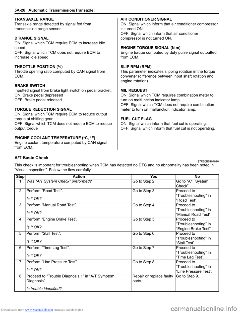
TRANSAXLE RANGE
Transaxle range detected by signal fed from
transmission range sensor.
D RANGE SIGNAL
ON: Signal which TCM require ECM to increase idle
speed
OFF: Signal which TCM does not require ECM to
increase idle speed
THROTTLE POSITION (%)
Throttle opening ratio computed by CAN signal from
ECM.
BRAKE SWITCH
Inputted signal from brake light switch on pedal bracket.
ON: Brake pedal depressed
OFF: Brake pedal released
TORQUE REDUCTION SIGNAL
ON: Signal which TCM require ECM to reduce output
torque at shifting gear
OFF: Signal which TCM does not require ECM to reduce
output torque
ENGINE COOLANT TEMPERATURE ( °C, °F)
Engine coolant temperature computed by CAN signal
from ECM. AIR CONDITIONER SIGNAL
ON: Signal which inform that air conditioner compressor
is turned ON.
OFF: Signal which inform that air conditioner
compressor is not turned ON.
ENGINE TORQUE SIGNAL (N
⋅m)
Engine torque computed by duty pulse signal outputted
from ECM.
SLIP RPM (RPM)
This parameter indicates slip ping rotation in the torque
converter (difference between input shaft rotation and
engine rotation)
MIL REQUEST
ON: Signal which TCM requires combination meter to
turn on malfunction indicator lamp.
OFF: Signal which TCM does not require combination
meter to turn on malf unction indicator lamp.
FUEL CUT FLAG
ON: Signal which inform that fuel cut is operating.
OFF: Signal which inform that fuel cut is not operating.
A/T Basic CheckS7RS0B5104010
This check is important for troubleshooting when TCM has detected no DTC and no abnormality has been noted in
“Visual Inspection”. Fo llow the flow carefully.
Step Action YesNo
1 Was “A/T System Check” preformed? Go to Step 2.Go to “A/T System
Check”.
2 Perform “Road Test”.
Is it OK? Go to Step 3.
Proceed to
“Troubleshooting” in
“Road Test”.
3 Perform “Manual Road Test”.
Is it OK? Go to Step 4.
Proceed to
“Troubleshooting” in
“Manual Road Test”.
4 Perform “Engine Brake Test”.
Is it OK? Go to Step 5.
Proceed to
“Troubleshooting” in
“Engine Brake Test”.
5 Perform “Stall Test”.
Is it OK? Go to Step 6.
Proceed to
“Troubleshooting” in
“Stall Test”.
6 Perform “Time Lag Test”.
Is it OK? Go to Step 7.
Proceed to
“Troubleshooting” in
“Time Lag Test”.
7 Perform “Line Pressure Test”.
Is it OK? Go to Step 8.
Proceed to
“Troubleshooting” in
“Line Pressure Test”.
8 Proceed to “Trouble Diag nosis 1” in “A/T Symptom
Diagnosis”.
Is trouble identified? Repair or replace faulty
parts.
Go to Step 9.
Page 678 of 1496
Downloaded from www.Manualslib.com manuals search engine 5A-34 Automatic Transmission/Transaxle:
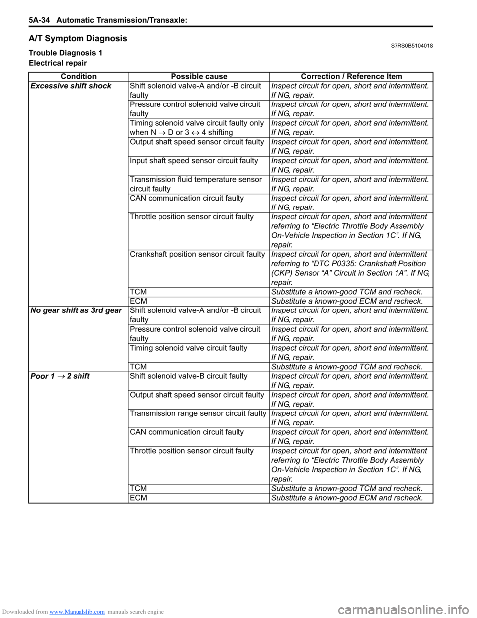
A/T Symptom DiagnosisS7RS0B5104018
Trouble Diagnosis 1
Electrical repair
Condition Possible cause Correction / Reference Item
Excessive shift shock Shift solenoid valve-A and/or -B circuit
faulty Inspect circuit for open, short and intermittent.
If NG, repair.
Pressure control solenoid valve circuit
faulty Inspect circuit for open, short and intermittent.
If NG, repair.
Timing solenoid valve circuit faulty only
when N → D or 3 ↔ 4 shifting Inspect circuit for open, short and intermittent.
If NG, repair.
Output shaft speed sensor circuit faulty Inspect circuit for open, short and intermittent.
If NG, repair.
Input shaft speed sensor circuit faulty Inspect circuit for open, short and intermittent.
If NG, repair.
Transmission fluid temperature sensor
circuit faulty Inspect circuit for open, short and intermittent.
If NG, repair.
CAN communication circuit faulty Inspect circuit for open, short and intermittent.
If NG, repair.
Throttle position sensor circuit faulty Inspect circuit for open, short and intermittent
referring to “Electric Throttle Body Assembly
On-Vehicle Inspection in Section 1C”. If NG,
repair.
Crankshaft position sensor circuit faulty Inspect circuit for open, short and intermittent
referring to “DTC P0335: Crankshaft Position
(CKP) Sensor “A” Circuit in Section 1A”. If NG,
repair.
TCM Substitute a known-good TCM and recheck.
ECM Substitute a known-good ECM and recheck.
No gear shift as 3rd gear Shift solenoid valve-A and/or -B circuit
faulty Inspect circuit for open, short and intermittent.
If NG, repair.
Pressure control solenoid valve circuit
faulty Inspect circuit for open, short and intermittent.
If NG, repair.
Timing solenoid valve circuit faulty Inspect circuit for open, short and intermittent.
If NG, repair.
TCM Substitute a known-good TCM and recheck.
Poor 1
→ 2 shift Shift solenoid valve-B circuit faulty Inspect circuit for open, short and intermittent.
If NG, repair.
Output shaft speed sensor circuit faulty Inspect circuit for open, short and intermittent.
If NG, repair.
Transmission range sensor circuit faulty Inspect circuit for open, short and intermittent.
If NG, repair.
CAN communication circuit faulty Inspect circuit for open, short and intermittent.
If NG, repair.
Throttle position sensor circuit faulty Inspect circuit for open, short and intermittent
referring to “Electric Throttle Body Assembly
On-Vehicle Inspection in Section 1C”. If NG,
repair.
TCM Substitute a known-good TCM and recheck.
ECM Substitute a known-good ECM and recheck.
Page 679 of 1496
Downloaded from www.Manualslib.com manuals search engine Automatic Transmission/Transaxle: 5A-35
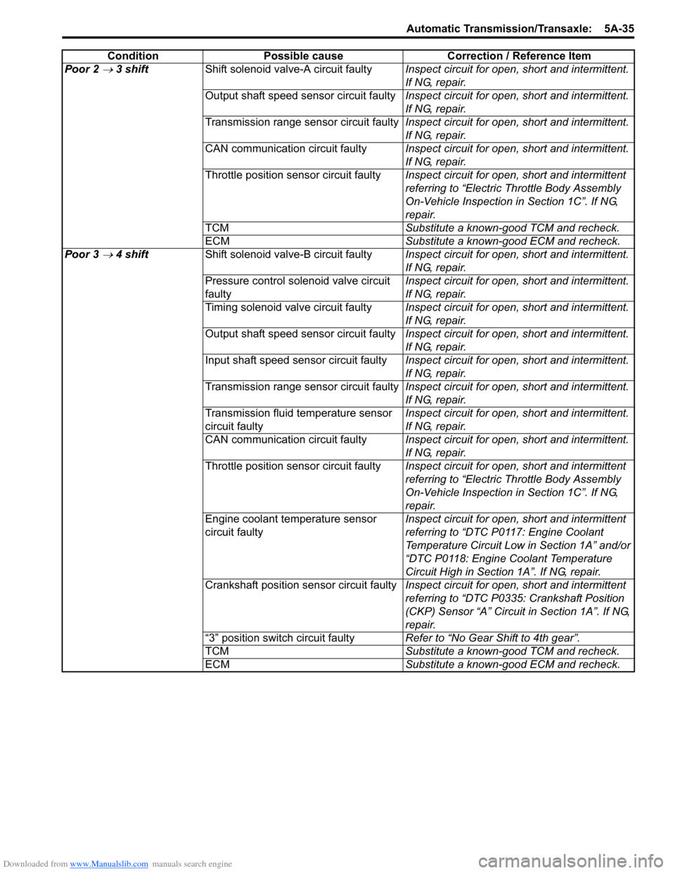
Poor 2 → 3 shiftShift solenoid valve-A circuit faulty Inspect circuit for open, short and intermittent.
If NG, repair.
Output shaft speed sensor circuit faulty Inspect circuit for open, short and intermittent.
If NG, repair.
Transmission range sensor circuit faulty Inspect circuit for open, short and intermittent.
If NG, repair.
CAN communication circuit faulty Inspect circuit for open, short and intermittent.
If NG, repair.
Throttle position sensor circuit faulty Inspect circuit for open, short and intermittent
referring to “Electric Throttle Body Assembly
On-Vehicle Inspection in Section 1C”. If NG,
repair.
TCM Substitute a known-good TCM and recheck.
ECM Substitute a known-good ECM and recheck.
Poor 3
→ 4 shift Shift solenoid valve-B circuit faulty Inspect circuit for open, short and intermittent.
If NG, repair.
Pressure control solenoid valve circuit
faulty Inspect circuit for open, short and intermittent.
If NG, repair.
Timing solenoid valve circuit faulty Inspect circuit for open, short and intermittent.
If NG, repair.
Output shaft speed sensor circuit faulty Inspect circuit for open, short and intermittent.
If NG, repair.
Input shaft speed sensor circuit faulty Inspect circuit for open, short and intermittent.
If NG, repair.
Transmission range sensor circuit faulty Inspect circuit for open, short and intermittent.
If NG, repair.
Transmission fluid temperature sensor
circuit faulty Inspect circuit for open, short and intermittent.
If NG, repair.
CAN communication circuit faulty Inspect circuit for open, short and intermittent.
If NG, repair.
Throttle position sensor circuit faulty Inspect circuit for open, short and intermittent
referring to “Electric Throttle Body Assembly
On-Vehicle Inspection in Section 1C”. If NG,
repair.
Engine coolant temperature sensor
circuit faulty Inspect circuit for open, short and intermittent
referring to “DTC P0117: Engine Coolant
Temperature Circuit Low
in Section 1A” and/or
“DTC P0118: Engine Coolant Temperature
Circuit High in Section 1A”. If NG, repair.
Crankshaft position sensor circuit faulty Inspect circuit for open, short and intermittent
referring to “DTC P0335: Crankshaft Position
(CKP) Sensor “A” Circuit in Section 1A”. If NG,
repair.
“3” position switch circuit faulty Refer to “No Gear Shift to 4th gear”.
TCM Substitute a known-good TCM and recheck.
ECM Substitute a known-good ECM and recheck.
Condition Possible cause Correction / Reference Item
Page 680 of 1496
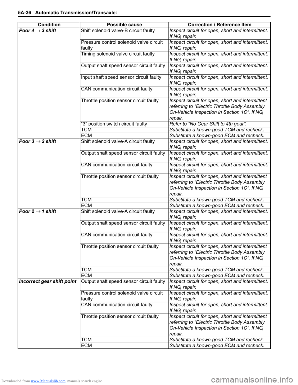
Downloaded from www.Manualslib.com manuals search engine 5A-36 Automatic Transmission/Transaxle:
Poor 4 → 3 shiftShift solenoid valve-B circuit faulty Inspect circuit for open, short and intermittent.
If NG, repair.
Pressure control solenoid valve circuit
faulty Inspect circuit for open, short and intermittent.
If NG, repair.
Timing solenoid valve circuit faulty Inspect circuit for open, short and intermittent.
If NG, repair.
Output shaft speed sensor circuit faulty Inspect circuit for open, short and intermittent.
If NG, repair.
Input shaft speed sensor circuit faulty Inspect circuit for open, short and intermittent.
If NG, repair.
CAN communication circuit faulty Inspect circuit for open, short and intermittent.
If NG, repair.
Throttle position sensor circuit faulty Inspect circuit for open, short and intermittent
referring to “Electric Throttle Body Assembly
On-Vehicle Inspection in Section 1C”. If NG,
repair.
“3” position switch circuit faulty Refer to “No Gear Shift to 4th gear”.
TCM Substitute a known-good TCM and recheck.
ECM Substitute a known-good ECM and recheck.
Poor 3
→ 2 shift Shift solenoid valve-A circuit faulty Inspect circuit for open, short and intermittent.
If NG, repair.
Output shaft speed sensor circuit faulty Inspect circuit for open, short and intermittent.
If NG, repair.
CAN communication circuit faulty Inspect circuit for open, short and intermittent.
If NG, repair.
Throttle position sensor circuit faulty Inspect circuit for open, short and intermittent
referring to “Electric Throttle Body Assembly
On-Vehicle Inspection in Section 1C”. If NG,
repair.
TCM Substitute a known-good TCM and recheck.
ECM Substitute a known-good ECM and recheck.
Poor 2
→ 1 shift Shift solenoid valve-A circuit faulty Inspect circuit for open, short and intermittent.
If NG, repair.
Output shaft speed sensor circuit faulty Inspect circuit for open, short and intermittent.
If NG, repair.
CAN communication circuit faulty Inspect circuit for open, short and intermittent.
If NG, repair.
Throttle position sensor circuit faulty Inspect circuit for open, short and intermittent
referring to “Electric Throttle Body Assembly
On-Vehicle Inspection in Section 1C”. If NG,
repair.
TCM Substitute a known-good TCM and recheck.
ECM Substitute a known-good ECM and recheck.
Incorrect gear shift point Output shaft speed sensor circuit faulty Inspect circuit for open, short and intermittent.
If NG, repair.
Pressure control solenoid valve circuit
faulty Inspect circuit for open, short and intermittent.
If NG, repair.
CAN communication circuit faulty Inspect circuit for open, short and intermittent.
If NG, repair.
Throttle position sensor circuit faulty Inspect circuit for open, short and intermittent
referring to “Electric Throttle Body Assembly
On-Vehicle Inspection in Section 1C”. If NG,
repair.
TCM Substitute a known-good TCM and recheck.
ECM Substitute a known-good ECM and recheck.
Condition Possible cause Correction / Reference Item
Page 681 of 1496
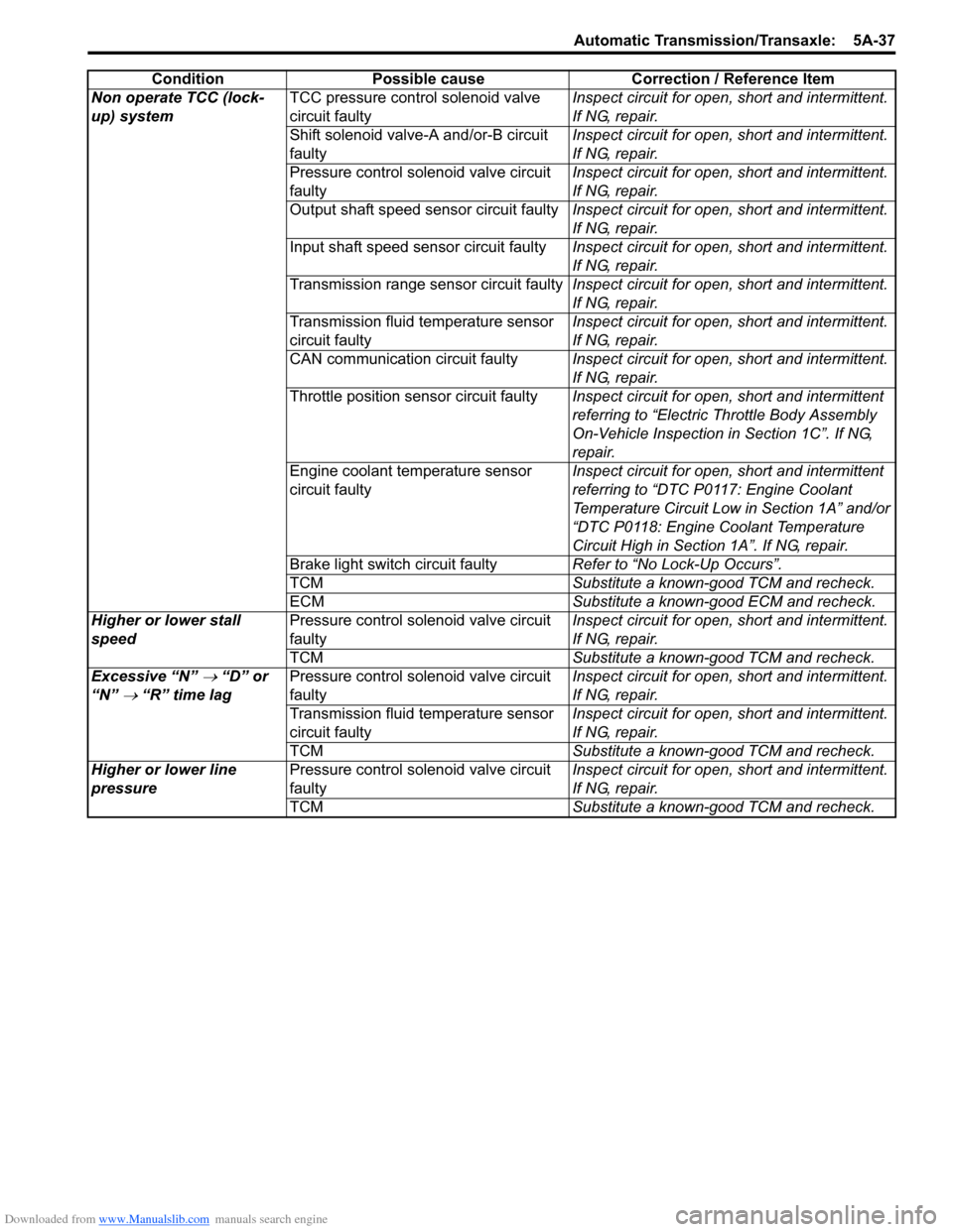
Downloaded from www.Manualslib.com manuals search engine Automatic Transmission/Transaxle: 5A-37
Non operate TCC (lock-
up) systemTCC pressure control solenoid valve
circuit faulty Inspect circuit for open, short and intermittent.
If NG, repair.
Shift solenoid valve-A and/or-B circuit
faulty Inspect circuit for open, short and intermittent.
If NG, repair.
Pressure control solenoid valve circuit
faulty Inspect circuit for open, short and intermittent.
If NG, repair.
Output shaft speed sensor circuit faulty Inspect circuit for open, short and intermittent.
If NG, repair.
Input shaft speed sensor circuit faulty Inspect circuit for open, short and intermittent.
If NG, repair.
Transmission range sensor circuit faulty Inspect circuit for open, short and intermittent.
If NG, repair.
Transmission fluid temperature sensor
circuit faulty Inspect circuit for open, short and intermittent.
If NG, repair.
CAN communication circuit faulty Inspect circuit for open, short and intermittent.
If NG, repair.
Throttle position sensor circuit faulty Inspect circuit for open, short and intermittent
referring to “Electric Throttle Body Assembly
On-Vehicle Inspection in Section 1C”. If NG,
repair.
Engine coolant temperature sensor
circuit faulty Inspect circuit for open, short and intermittent
referring to “DTC P0117: Engine Coolant
Temperature Circuit Low
in Section 1A” and/or
“DTC P0118: Engine Coolant Temperature
Circuit High in Section 1A”. If NG, repair.
Brake light switch circuit faulty Refer to “No Lock-Up Occurs”.
TCM Substitute a known-good TCM and recheck.
ECM Substitute a known-good ECM and recheck.
Higher or lower stall
speed Pressure control solenoid valve circuit
faulty Inspect circuit for open, short and intermittent.
If NG, repair.
TCM Substitute a known-good TCM and recheck.
Excessive “N”
→ “D” or
“N”
→ “R” time lag Pressure control solenoid valve circuit
faulty Inspect circuit for open, short and intermittent.
If NG, repair.
Transmission fluid temperature sensor
circuit faulty Inspect circuit for open, short and intermittent.
If NG, repair.
TCM Substitute a known-good TCM and recheck.
Higher or lower line
pressure Pressure control solenoid valve circuit
faulty Inspect circuit for open, short and intermittent.
If NG, repair.
TCM Substitute a known-good TCM and recheck.
Condition Possible cause Correction / Reference Item
Page 688 of 1496
Downloaded from www.Manualslib.com manuals search engine 5A-44 Automatic Transmission/Transaxle:
DTC P0602: Control Module Programming ErrorS7RS0B5104048
System Description
Internal control module is installed in ECM.
DTC Detecting Condition and Trouble Area
DTC Confirmation Procedure 1) Connect scan tool to DLC with ignition switch turned OFF.
2) Clear DTC, pending DTC and freeze frame data by using scan tool.
3) Start engine and run it at idle if possible.
4) Check DTC.
DTC Troubleshooting
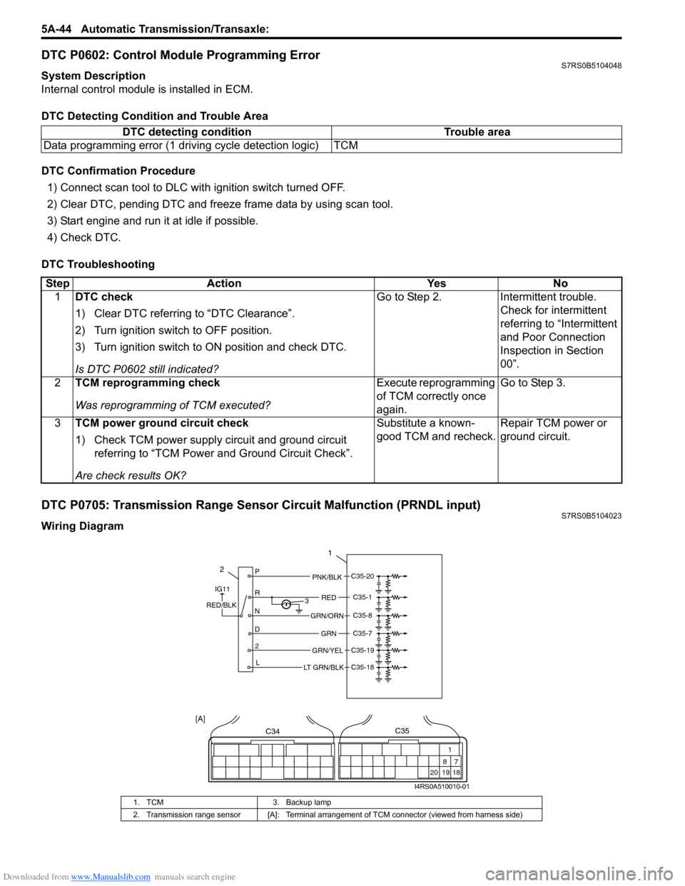
DTC P0705: Transmission Range Sensor Circuit Malfunction (PRNDL input)S7RS0B5104023
Wiring DiagramDTC detecting condition Trouble area
Data programming error (1 driving cycle detection logic) TCM
Step Action YesNo
1 DTC check
1) Clear DTC referring to “DTC Clearance”.
2) Turn ignition switch to OFF position.
3) Turn ignition switch to ON position and check DTC.
Is DTC P0602 still indicated? Go to Step 2.
Intermittent trouble.
Check for intermittent
referring to “Intermittent
and Poor Connection
Inspection in Section
00”.
2 TCM reprogramming check
Was reprogramming of TCM executed? Execute reprogramming
of TCM correctly once
again.Go to Step 3.
3 TCM power ground circuit check
1) Check TCM power supply circuit and ground circuit
referring to “TCM Power and Ground Circuit Check”.
Are check results OK? Substitute a known-
good TCM and recheck.
Repair TCM power or
ground circuit.
1. TCM
3. Backup lamp
2. Transmission range sensor [A]: Terminal arrangem ent of TCM connector (viewed from harness side)
2P
R
N
D 2 L 3
1
PNK/BLK
RED
GRN
GRN/ORN
GRN/YEL
IG11
RED/BLK
LT GRN/BLK
C35-20
C35-1
C35-8
C35-7
C35-19
C35-18
C34
20 19
87
18
1
C35
[A]
I4RS0A510010-01
Page 696 of 1496
Downloaded from www.Manualslib.com manuals search engine 5A-52 Automatic Transmission/Transaxle:
DTC P0722: Output Speed Sensor Circuit No SignalS7RS0B5104028
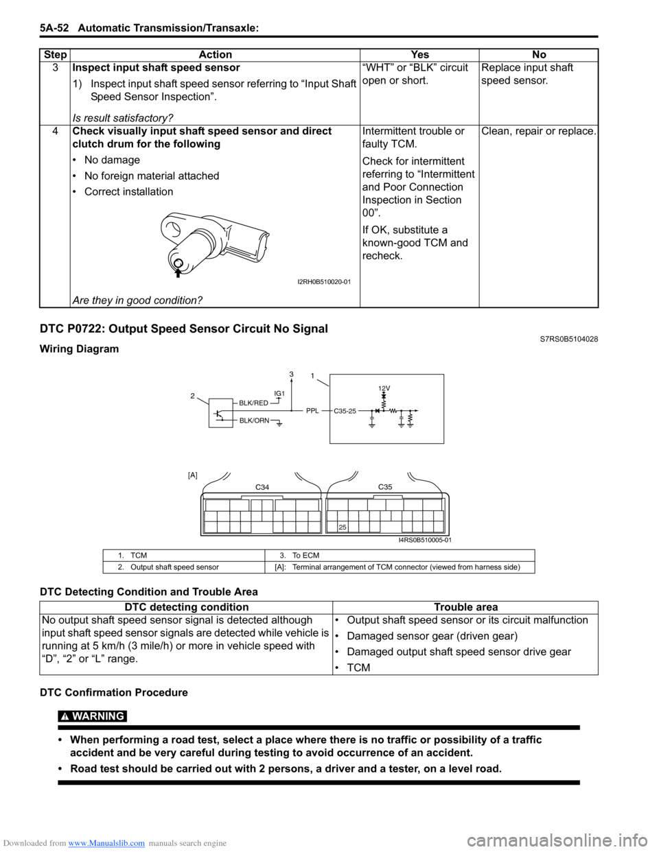
Wiring Diagram
DTC Detecting Condition and Trouble Area
DTC Confirmation Procedure
WARNING!
• When performing a road test, select a place where there is no traffic or possibility of a traffic
accident and be very careful during testing to avoid occurrence of an accident.
• Road test should be carried out with 2 persons, a driver and a tester, on a level road.
3 Inspect input shaft speed sensor
1) Inspect input shaft speed sensor referring to “Input Shaft
Speed Sensor Inspection”.
Is result satisfactory? “WHT” or “BLK” circuit
open or short.
Replace input shaft
speed sensor.
4 Check visually input shaft speed sensor and direct
clutch drum for the following
• No damage
• No foreign material attached
• Correct installation
Are they in good condition? Intermittent trouble or
faulty TCM.
Check for intermittent
referring to “Intermittent
and Poor Connection
Inspection in Section
00”.
If OK, substitute a
known-good TCM and
recheck.
Clean, repair or replace.
Step Action Yes No
I2RH0B510020-01
1. TCM
3. To ECM
2. Output shaft speed sensor [A]: Terminal arrangement of TCM connector (viewed from harness side)
DTC detecting condition Trouble area
No output shaft speed sensor signal is detected although
input shaft speed sensor signal s are detected while vehicle is
running at 5 km/h (3 mile/h) or more in vehicle speed with
“D”, “2” or “L” range. • Output shaft speed sensor or its circuit malfunction
• Damaged sensor gear (driven gear)
• Damaged output shaft speed sensor drive gear
•TCM
IG112V
PPLC35-25
2
C34
25
C35
[A]
1
BLK/RED
BLK/ORN
3
I4RS0B510005-01
Page 714 of 1496
Downloaded from www.Manualslib.com manuals search engine 5A-70 Automatic Transmission/Transaxle:
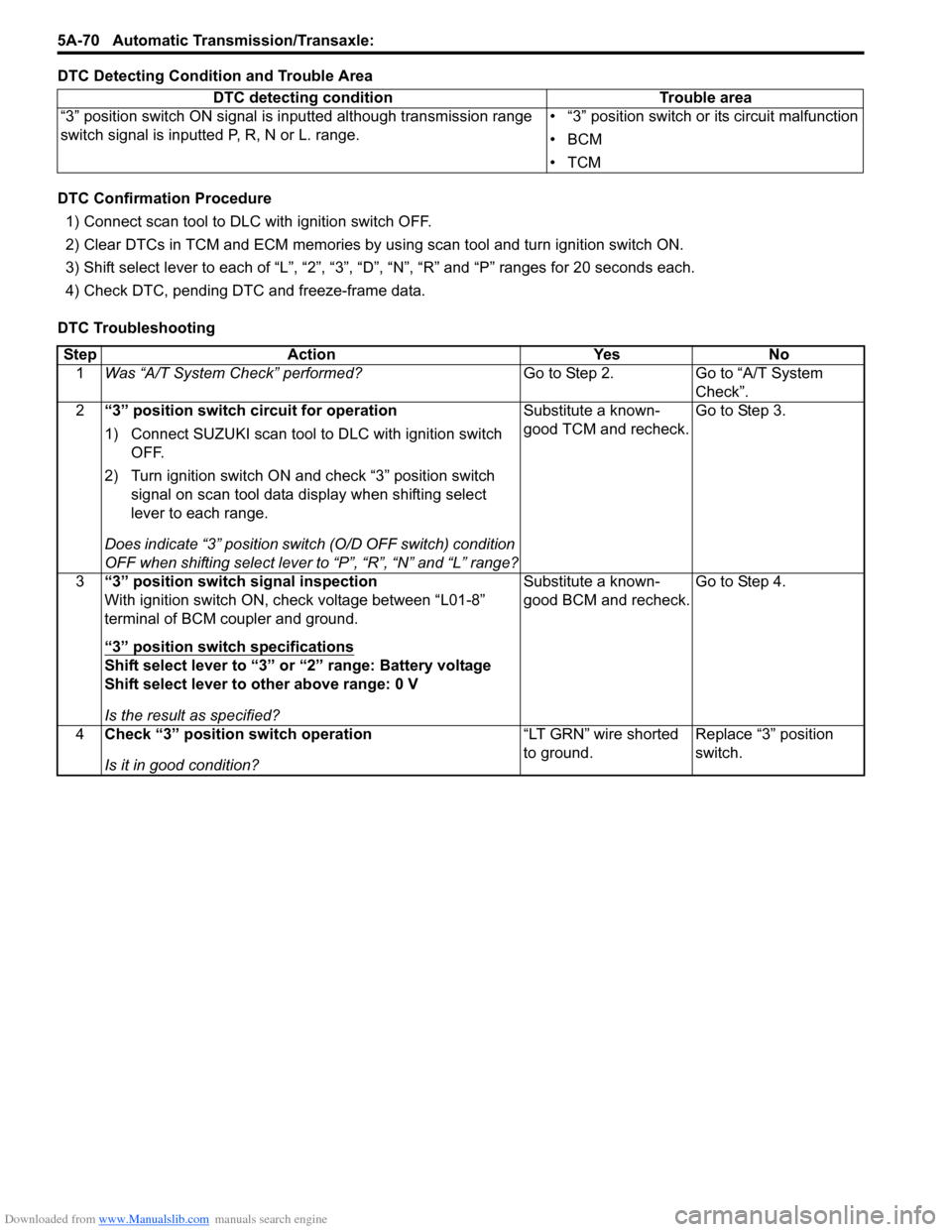
DTC Detecting Condition and Trouble Area
DTC Confirmation Procedure
1) Connect scan tool to DLC with ignition switch OFF.
2) Clear DTCs in TCM and ECM memories by us ing scan tool and turn ignition switch ON.
3) Shift select lever to each of “L”, “2”, “3”, “D”, “N”, “R” and “P” ranges for 20 seconds each.
4) Check DTC, pending DTC and freeze-frame data.
DTC Troubleshooting DTC detecting condition Trouble area
“3” position switch ON signal is inputted although transmission range
switch signal is inputted P, R, N or L. range. • “3” position switch or its circuit malfunction
•BCM
•TCM
Step
Action YesNo
1 Was “A/T System Check” performed? Go to Step 2.Go to “A/T System
Check”.
2 “3” position switch circuit for operation
1) Connect SUZUKI scan tool to DLC with ignition switch
OFF.
2) Turn ignition switch ON and check “3” position switch signal on scan tool data display when shifting select
lever to each range.
Does indicate “3” position swit ch (O/D OFF switch) condition
OFF when shifting select lever to “P”, “R”, “N” and “L” range? Substitute a known-
good TCM and recheck.
Go to Step 3.
3 “3” position switch signal inspection
With ignition switch ON, check voltage between “L01-8”
terminal of BCM coupler and ground.
“3” position switch specifications
Shift select lever to “3” or “2” range: Battery voltage
Shift select lever to other above range: 0 V
Is the result as specified? Substitute a known-
good BCM and recheck.
Go to Step 4.
4 Check “3” position switch operation
Is it in good condition? “LT GRN” wire shorted
to ground.
Replace “3” position
switch.
Page 894 of 1496
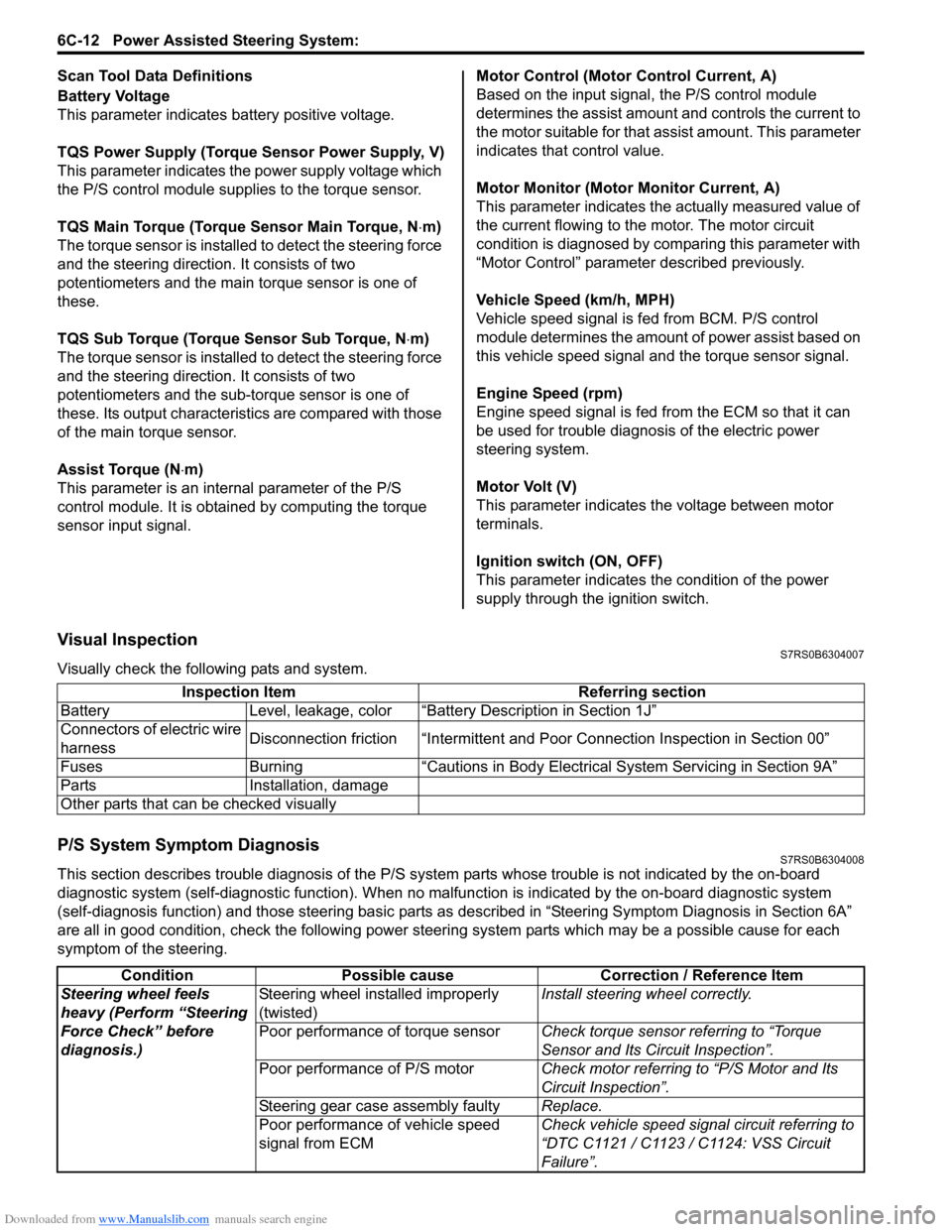
Downloaded from www.Manualslib.com manuals search engine 6C-12 Power Assisted Steering System:
Scan Tool Data Definitions
Battery Voltage
This parameter indicates battery positive voltage.
TQS Power Supply (Torque Sensor Power Supply, V)
This parameter indicates the power supply voltage which
the P/S control module supplies to the torque sensor.
TQS Main Torque (Torque Sensor Main Torque, N ⋅m)
The torque sensor is installed to detect the steering force
and the steering directio n. It consists of two
potentiometers and the main torque sensor is one of
these.
TQS Sub Torque (Torque Sensor Sub Torque, N ⋅m)
The torque sensor is installed to detect the steering force
and the steering directio n. It consists of two
potentiometers and the sub-torque sensor is one of
these. Its output characteristics are compared with those
of the main torque sensor.
Assist Torque (N ⋅m)
This parameter is an internal parameter of the P/S
control module. It is obtained by computing the torque
sensor input signal. Motor Control (Motor Control Current, A)
Based on the input signal, the P/S control module
determines the assist amount
and controls the current to
the motor suitable for that a ssist amount. This parameter
indicates that control value.
Motor Monitor (Motor Monitor Current, A)
This parameter indicates the actually measured value of
the current flowing to the motor. The motor circuit
condition is diagnosed by co mparing this parameter with
“Motor Control” parameter described previously.
Vehicle Speed (km/h, MPH)
Vehicle speed signal is fed from BCM. P/S control
module determines the amount of power assist based on
this vehicle speed signal and the torque sensor signal.
Engine Speed (rpm)
Engine speed signal is fed from the ECM so that it can
be used for trouble diagnos is of the electric power
steering system.
Motor Volt (V)
This parameter indicates the voltage between motor
terminals.
Ignition switch (ON, OFF)
This parameter indicates the condition of the power
supply through the ignition switch.
Visual InspectionS7RS0B6304007
Visually check the following pats and system.
P/S System Symptom DiagnosisS7RS0B6304008
This section describes trouble diagnosis of the P/S system parts whose trouble is not indicated by the on-board
diagnostic system (self-diagnostic functi on). When no malfunction is indicated by the on-board diagnostic system
(self-diagnosis function) and those stee ring basic parts as described in “Steering Symptom Diagnosis in Section 6A”
are all in good condition, check the following power steer ing system parts which may be a possible cause for each
symptom of the steering. Inspection Item Referring section
Battery Level, leakage, color “Batte ry Description in Section 1J”
Connectors of electric wire
harness Disconnection friction “Intermittent and Poor
Connection Inspection in Section 00”
Fuses Burning “Cautions in Body Electric al System Servicing in Section 9A”
Parts Installation, damage
Other parts that can be checked visually
Condition Possible cause Correction / Reference Item
Steering wheel feels
heavy (Perform “Steering
Force Check” before
diagnosis.) Steering wheel installed improperly
(twisted)
Install steering wheel correctly.
Poor performance of torque sensor Check torque sensor referring to “Torque
Sensor and Its Circuit Inspection”.
Poor performance of P/S motor Check motor referring to “P/S Motor and Its
Circuit Inspection”.
Steering gear case assembly faulty Replace.
Poor performance of vehicle speed
signal from ECM Check vehicle speed signal circuit referring to
“DTC C1121 / C1123 / C1124: VSS Circuit
Failure”.