checking engine SUZUKI SWIFT 2008 2.G Service Service Manual
[x] Cancel search | Manufacturer: SUZUKI, Model Year: 2008, Model line: SWIFT, Model: SUZUKI SWIFT 2008 2.GPages: 1496, PDF Size: 34.44 MB
Page 667 of 1496
Downloaded from www.Manualslib.com manuals search engine Automatic Transmission/Transaxle: 5A-23
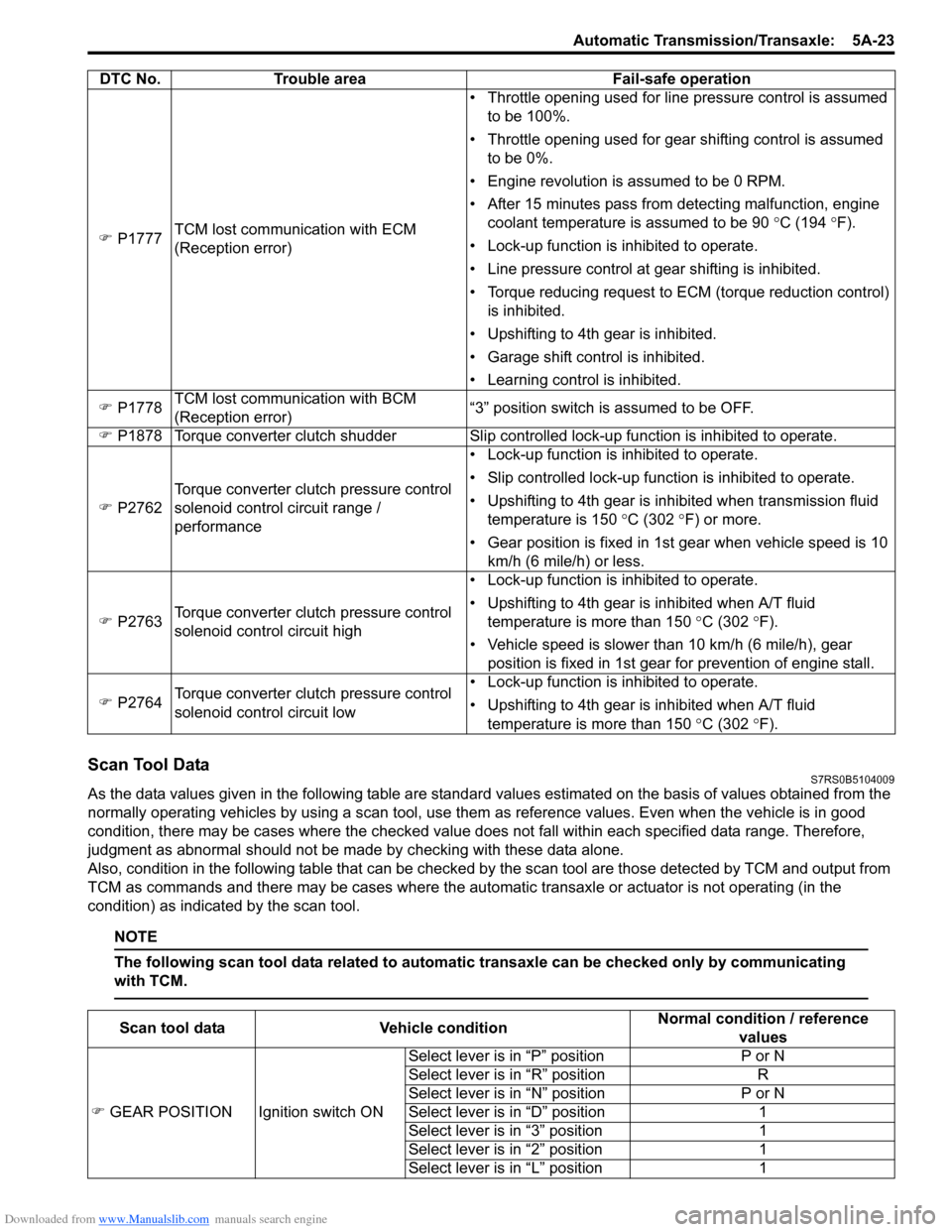
Scan Tool DataS7RS0B5104009
As the data values given in the following table are standard values estimated on the basis of values obtained from the
normally operating vehicles by using a scan tool, use them as reference values. Even when the vehicle is in good
condition, there may be cases where the checked value does not fall within each specified data range. Therefore,
judgment as abnormal should not be made by checking with these data alone.
Also, condition in the following table that can be checked by the scan tool are those detected by TCM and output from
TCM as commands and there may be cases where the auto matic transaxle or actuator is not operating (in the
condition) as indicated by the scan tool.
NOTE
The following scan tool data related to automatic transaxle can be checked only by communicating
with TCM.
�) P1777 TCM lost communication with ECM
(Reception error) • Throttle opening used for line pressure control is assumed
to be 100%.
• Throttle opening used for gear shifting control is assumed to be 0%.
• Engine revolution is assumed to be 0 RPM.
• After 15 minutes pass from detecting malfunction, engine coolant temperature is assumed to be 90 °C (194 °F).
• Lock-up function is inhibited to operate.
• Line pressure control at gear shifting is inhibited.
• Torque reducing request to ECM (torque reduction control) is inhibited.
• Upshifting to 4th gear is inhibited.
• Garage shift control is inhibited.
• Learning control is inhibited.
�) P1778 TCM lost communication with BCM
(Reception error) “3” position switch is assumed to be OFF.
�) P1878 Torque converter clutch shudder Slip contro lled lock-up function is inhibited to operate.
�) P2762 Torque converter clutch pressure control
solenoid control circuit range /
performance • Lock-up function is inhibited to operate.
• Slip controlled lock-up function is inhibited to operate.
• Upshifting to 4th gear is inhibited when transmission fluid
temperature is 150 °C (302 ° F) or more.
• Gear position is fixed in 1st gear when vehicle speed is 10 km/h (6 mile/h) or less.
�) P2763 Torque converter clutch pressure control
solenoid control circuit high • Lock-up function is inhibited to operate.
• Upshifting to 4th gear is inhibited when A/T fluid
temperature is more than 150 °C (302 °F).
• Vehicle speed is slower than 10 km/h (6 mile/h), gear position is fixed in 1st gear for prevention of engine stall.
�) P2764 Torque converter clutch pressure control
solenoid control circuit low • Lock-up function is inhibited to operate.
• Upshifting to 4th gear is inhibited when A/T fluid
temperature is more than 150 °C (302 °F).
DTC No. Trouble area Fail-safe operation
Scan tool data
Vehicle condition Normal condition / reference
values
�) GEAR POSITION Ignition switch ON Select lever is in “P” position
P or N
Select lever is in “R” position R
Select lever is in “N” position P or N
Select lever is in “D” position 1
Select lever is in “3” position 1
Select lever is in “2” position 1
Select lever is in “L” position 1
Page 712 of 1496
Downloaded from www.Manualslib.com manuals search engine 5A-68 Automatic Transmission/Transaxle:
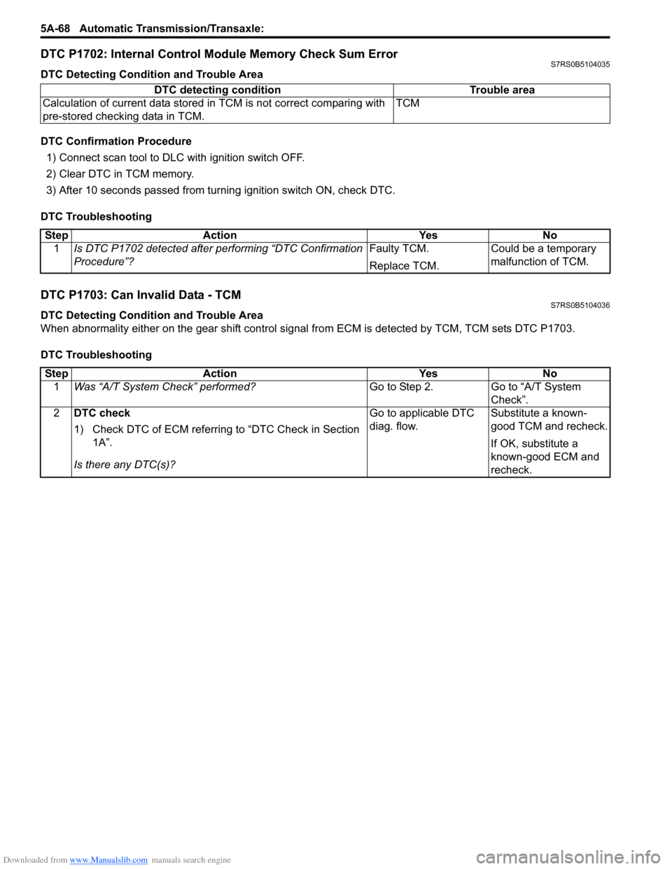
DTC P1702: Internal Control Module Memory Check Sum ErrorS7RS0B5104035
DTC Detecting Condition and Trouble Area
DTC Confirmation Procedure
1) Connect scan tool to DLC with ignition switch OFF.
2) Clear DTC in TCM memory.
3) After 10 seconds passed from turning ignition switch ON, check DTC.
DTC Troubleshooting
DTC P1703: Can Invalid Data - TCMS7RS0B5104036
DTC Detecting Condition and Trouble Area
When abnormality either on the gear shift control signal from ECM is detected by TCM, TCM sets DTC P1703.
DTC Troubleshooting DTC detecting condition Trouble area
Calculation of current data stored in TCM is not correct comparing with
pre-stored checking data in TCM. TCM
Step
Action YesNo
1 Is DTC P1702 detected after performing “DTC Confirmation
Procedure”? Faulty TCM.
Replace TCM.Could be a temporary
malfunction of TCM.
Step
Action YesNo
1 Was “A/T System Check” performed? Go to Step 2.Go to “A/T System
Check”.
2 DTC check
1) Check DTC of ECM referring to “DTC Check in Section
1A”.
Is there any DTC(s)? Go to applicable DTC
diag. flow.
Substitute a known-
good TCM and recheck.
If OK, substitute a
known-good ECM and
recheck.
Page 716 of 1496
Downloaded from www.Manualslib.com manuals search engine 5A-72 Automatic Transmission/Transaxle:
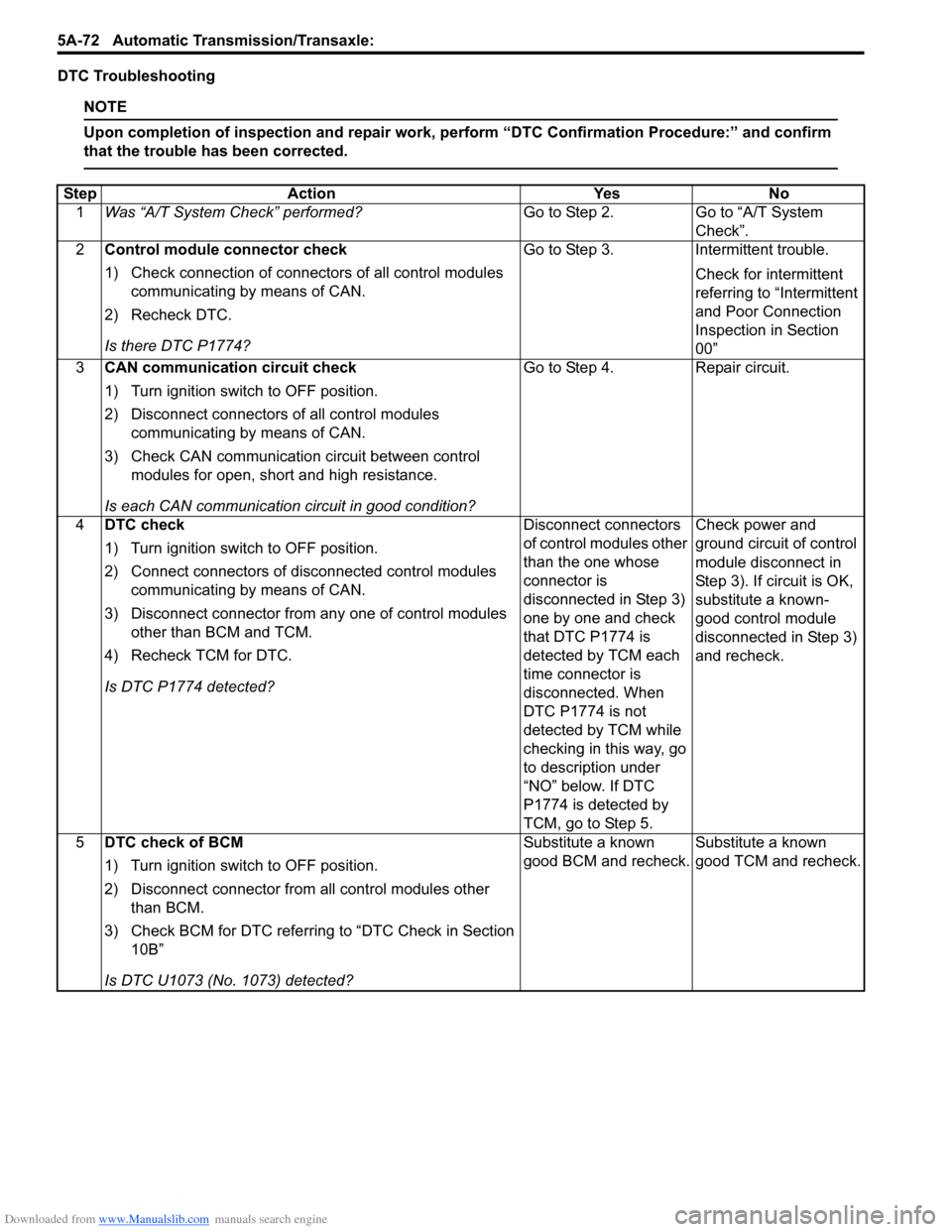
DTC Troubleshooting
NOTE
Upon completion of inspection and repair work, perform “DTC Confirmation Procedure:” and confirm
that the trouble has been corrected.
Step Action YesNo
1 Was “A/T System Check” performed? Go to Step 2.Go to “A/T System
Check”.
2 Control module connector check
1) Check connection of connectors of all control modules
communicating by means of CAN.
2) Recheck DTC.
Is there DTC P1774? Go to Step 3.
Intermittent trouble.
Check for intermittent
referring to “Intermittent
and Poor Connection
Inspection in Section
00”
3 CAN communication circuit check
1) Turn ignition switch to OFF position.
2) Disconnect connectors of all control modules
communicating by means of CAN.
3) Check CAN communication circuit between control modules for open, short and high resistance.
Is each CAN communication circuit in good condition? Go to Step 4.
Repair circuit.
4 DTC check
1) Turn ignition switch to OFF position.
2) Connect connectors of disconnected control modules
communicating by means of CAN.
3) Disconnect connector from any one of control modules other than BCM and TCM.
4) Recheck TCM for DTC.
Is DTC P1774 detected? Disconnect connectors
of control modules other
than the one whose
connector is
disconnected in Step 3)
one by one and check
that DTC P1774 is
detected by TCM each
time connector is
disconnected. When
DTC P1774 is not
detected by TCM while
checking in this way, go
to description under
“NO” below. If DTC
P1774 is detected by
TCM, go to Step 5.Check power and
ground circuit of control
module disconnect in
Step 3). If circuit is OK,
substitute a known-
good control module
disconnected in Step 3)
and recheck.
5 DTC check of BCM
1) Turn ignition switch to OFF position.
2) Disconnect connector from all control modules other
than BCM.
3) Check BCM for DTC referring to “DTC Check in Section 10B”
Is DTC U1073 (No. 1073) detected? Substitute a known
good BCM and recheck.
Substitute a known
good TCM and recheck.
Page 733 of 1496
Downloaded from www.Manualslib.com manuals search engine Automatic Transmission/Transaxle: 5A-89
A/T Fluid Level CheckS7RS0B5106002
CAUTION!
Do not use any fluid other than the specified
ATF. Use of any fluid other than the specified
ATF may cause juddering or some other
faulty condition to occur.
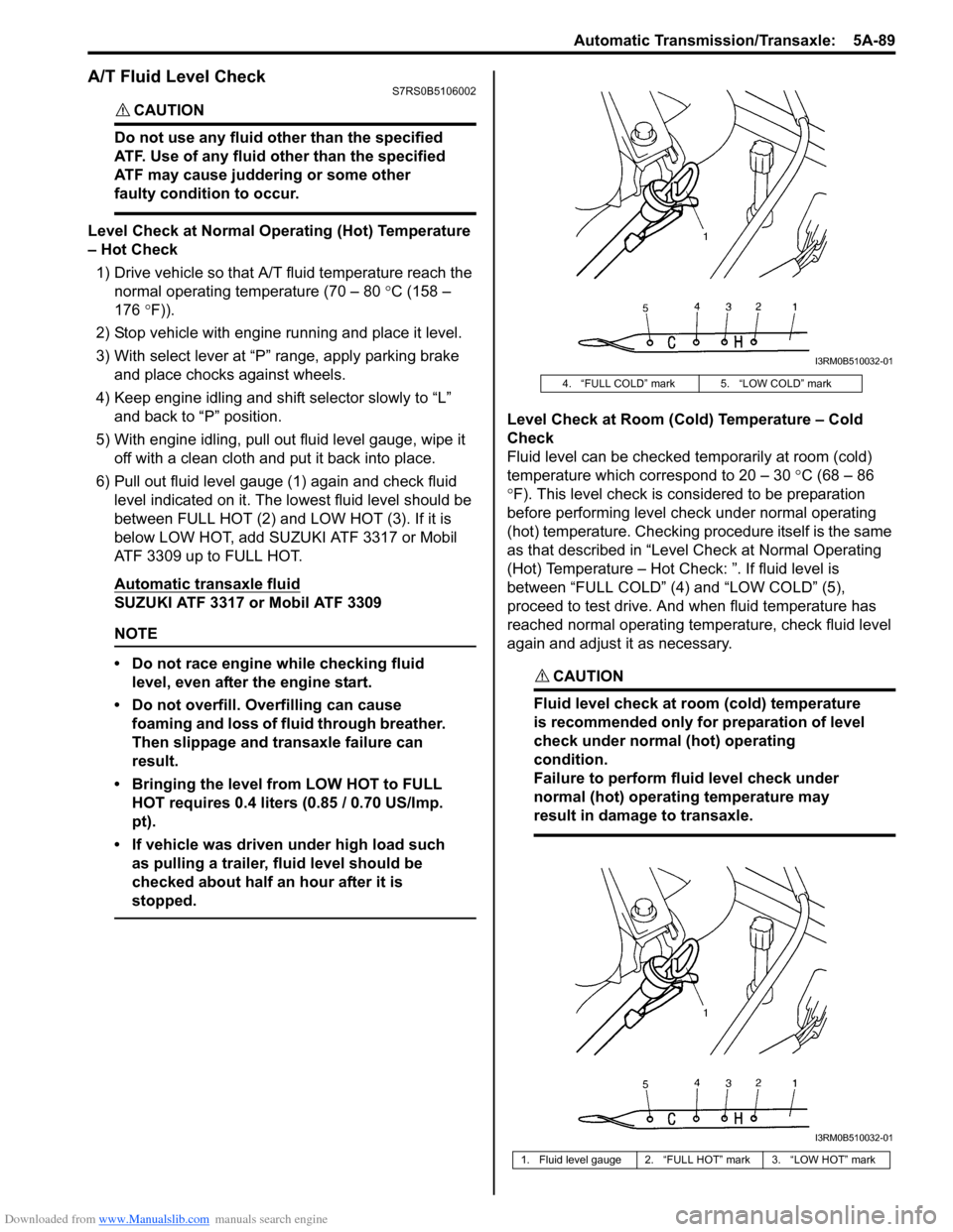
Level Check at Normal Operating (Hot) Temperature
– Hot Check1) Drive vehicle so that A/T fluid temperature reach the
normal operating temperature (70 – 80 °C (158 –
176 °F)).
2) Stop vehicle with engine running and place it level.
3) With select lever at “P” range, apply parking brake and place chocks against wheels.
4) Keep engine idling and shift selector slowly to “L” and back to “P” position.
5) With engine idling, pull out fluid level gauge, wipe it off with a clean cloth and put it back into place.
6) Pull out fluid level gauge (1) again and check fluid level indicated on it. The lo west fluid level should be
between FULL HOT (2) and LOW HOT (3). If it is
below LOW HOT, add SUZUKI ATF 3317 or Mobil
ATF 3309 up to FULL HOT.
Automatic transaxle fluid
SUZUKI ATF 3317 or Mobil ATF 3309
NOTE
• Do not race engine while checking fluid level, even after the engine start.
• Do not overfill. Overfilling can cause foaming and loss of fluid through breather.
Then slippage and transaxle failure can
result.
• Bringing the level from LOW HOT to FULL HOT requires 0.4 liters (0.85 / 0.70 US/Imp.
pt).
• If vehicle was driven under high load such as pulling a trailer, fluid level should be
checked about half an hour after it is
stopped.
Level Check at Room (Cold) Temperature – Cold
Check
Fluid level can be checked temporarily at room (cold)
temperature which correspond to 20 – 30 °C (68 – 86
° F). This level check is considered to be preparation
before performing level check under normal operating
(hot) temperature. Checking procedure itself is the same
as that described in “Level Check at Normal Operating
(Hot) Temperature – Hot Check: ”. If fluid level is
between “FULL COLD” (4) and “LOW COLD” (5),
proceed to test drive. And when fluid temperature has
reached normal operating temp erature, check fluid level
again and adjust it as necessary.
CAUTION!
Fluid level check at room (cold) temperature
is recommended only for preparation of level
check under normal (hot) operating
condition.
Failure to perform fluid level check under
normal (hot) operating temperature may
result in damage to transaxle.
4. “FULL COLD” mark 5. “LOW COLD” mark
1. Fluid level gauge 2. “FULL HOT” mark 3. “LOW HOT” mark
I3RM0B510032-01
I3RM0B510032-01
Page 744 of 1496
Downloaded from www.Manualslib.com manuals search engine 5A-100 Automatic Transmission/Transaxle:
Operation Check
Shift solenoid valve-A (No.1) and -B (No.2)
CAUTION!
• Do not insert air gun against strainer installed on inlet of solenoid valve too
deeply, when blowing air into solenoid
valve. If not, the strainer will be damaged.
• Be very careful as dust etc. does not enter when solenoid valves are inspected.
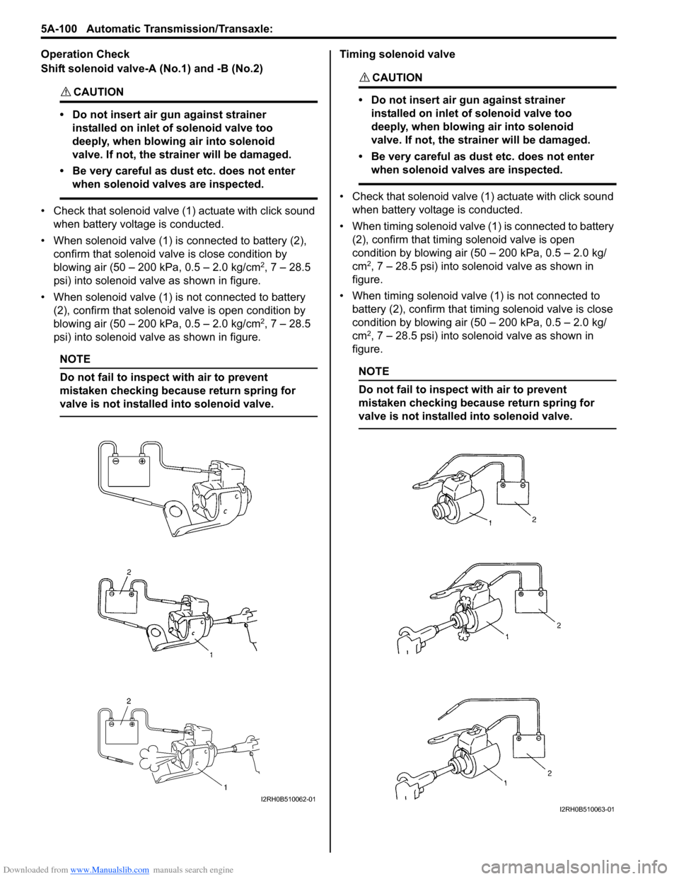
• Check that solenoid valve (1) actuate with click sound when battery voltage is conducted.
• When solenoid valve (1) is connected to battery (2), confirm that solenoid valve is close condition by
blowing air (50 – 200 kPa, 0.5 – 2.0 kg/cm
2, 7 – 28.5
psi) into solenoid valve as shown in figure.
• When solenoid valve (1) is not connected to battery (2), confirm that solenoid valve is open condition by
blowing air (50 – 200 kPa, 0.5 – 2.0 kg/cm
2, 7 – 28.5
psi) into solenoid valve as shown in figure.
NOTE
Do not fail to inspect with air to prevent
mistaken checking because return spring for
valve is not installe d into solenoid valve.
Timing solenoid valve
CAUTION!
• Do not insert air gun against strainer
installed on inlet of solenoid valve too
deeply, when blowing air into solenoid
valve. If not, the strainer will be damaged.
• Be very careful as dust etc. does not enter when solenoid valves are inspected.
• Check that solenoid valve (1) actuate with click sound
when battery voltage is conducted.
• When timing solenoid valve (1 ) is connected to battery
(2), confirm that timing solenoid valve is open
condition by blowing air (50 – 200 kPa, 0.5 – 2.0 kg/
cm
2, 7 – 28.5 psi) into solenoid valve as shown in
figure.
• When timing solenoid valve (1) is not connected to battery (2), confirm that timi ng solenoid valve is close
condition by blowing air (50 – 200 kPa, 0.5 – 2.0 kg/
cm
2, 7 – 28.5 psi) into solenoid valve as shown in
figure.
NOTE
Do not fail to inspect with air to prevent
mistaken checking because return spring for
valve is not installed into solenoid valve.
I2RH0B510062-01I2RH0B510063-01
Page 867 of 1496

Downloaded from www.Manualslib.com manuals search engine Table of Contents 6- i
6
Section 6
CONTENTS
Steering
Precautions ................................................. 6-1
Precautions............................................................. 6-1
Precautions on Steering........................................ 6-1
Steering General Diagnosi s.................... 6A-1
Precautions........................................................... 6A-1
Precautions for Steering Diagnosis ..................... 6A-1
Diagnostic Information and Procedures ............ 6A-2 Steering Symptom Diagnosis .............................. 6A-2
Steering Wheel and Column ................... 6B-1
Precautions........................................................... 6B-1
Service Precautions of Steering Wheel and Column.............................................................. 6B-1
General Description ............................................. 6B-1 Steering Wheel and Column Construction .......... 6B-1
Diagnostic Information and Procedures ............ 6B-2 Checking Steering Column for Accident Damage ............................................................ 6B-2
Repair Instructions .............................................. 6B-3 Steering Wheel and Column Construction .......... 6B-3
Steering Wheel Removal and Installation ........... 6B-4
Contact Coil Cable Assembly Removal and Installation ......................................................... 6B-5
Centering Contact Coil Cable Assembly ............. 6B-6
Contact Coil Cable Assembly Inspection ............ 6B-6
Steering Angle Sensor Removal and Installation ......................................................... 6B-6
Steering Angle Sensor Inspection ....................... 6B-6
Steering Column Removal and Installation ......... 6B-7
Steering Column Inspecti on ................................ 6B-8
Ignition Switch Cylinder Assembly Removal and Installation (Non- Keyless Start Model)...... 6B-9
Steering Lock Assembly (Ignition Switch) Removal and Installation................................... 6B-9
Steering Lower Shaft Removal and Installation ....................................................... 6B-10
Specifications ..................................................... 6B-11
Tightening Torque Specifications ...................... 6B-11
Special Tools and Equipmen t ........................... 6B-11
Special Tool ...................................................... 6B-11
Power Assisted Steering System........... 6C-1
Precautions........................................................... 6C-1 Steering System Note .........................................6C-1
Precautions in Diagnosing Troubles ...................6C-1
General Description .............................................6C-2 P/S System Description ......................................6C-2
EPS Diagnosis General Descr iption ...................6C-3
On-Board Diagnostic System Description ...........6C-3
Schematic and Routing Diagram ........................6C-4 EPS System Wiring Circuit Diagram ...................6C-4
Diagnostic Information and Procedures ............6C-5 EPS System Check .............. ...............................6C-5
“EPS” Warning Light Check . ...............................6C-8
DTC Check..........................................................6C-8
DTC Clearance ...................................................6C-9
DTC Table ...........................................................6C-9
Scan Tool Data .................................................6C-11
Visual Inspection ...............................................6C-12
P/S System Symptom Diagnosis ......................6C-12
Serial Data Link Circuit Check ..........................6C-13
“EPS” Warning Light Do es Not Come ON with
Ignition Switch Turn ed ON before Engine
Starts ...............................................................6C-15
“EPS” Warning Light Remains ON Steady after Engine Starts ..........................................6C-16
DTC C1113: Steering Torque Sensor (Main and Sub) Circuit Correlation ............................6C-17
DTC C1114: Steering Torque Sensor Reference Power Supply Circuit .....................6C-19
DTC C1117: Steering Torque Sensor Failure Signal Circuit Low ...........................................6C-21
DTC C1118: Steering Torque Sensor Failure Signal Circuit High...........................................6C-22
DTC C1119: Steering Torque Sensor Power Supply Circuit ..................................................6C-24
DTC C1121 / C1123 / C1124: VSS Circuit
Failure .............................................................6C-26
DTC C1122: Engine Speed Signal....................6C-28
DTC C1141 / C1142 / C1143 / C1145: P/S Motor Circuit Failure ........................................6C-30
DTC C1153: P/S Control Module Power Supply Circuit Voltage Low .............................6C-32
DTC C1155: P/S Control Module Failure ..........6C-33
P/S Control Module Power Supply and Ground Circuit Check ......................................6C-34
Inspection of P/S Control Module and Its Circuits ............................................................6C-35
Page 873 of 1496
Downloaded from www.Manualslib.com manuals search engine Steering Wheel and Column: 6B-2
Diagnostic Information and Procedures
Checking Steering Column for Accident
Damage
S7RS0B6204001
NOTE
Vehicles involved in accidents resulting in
body damage, where steering column has
been impacted or air bag deployed may have
a damaged or misaligned steering column.
Checking Procedure
NOTE
The steering column used in each vehicle is
one of the two types as shown.
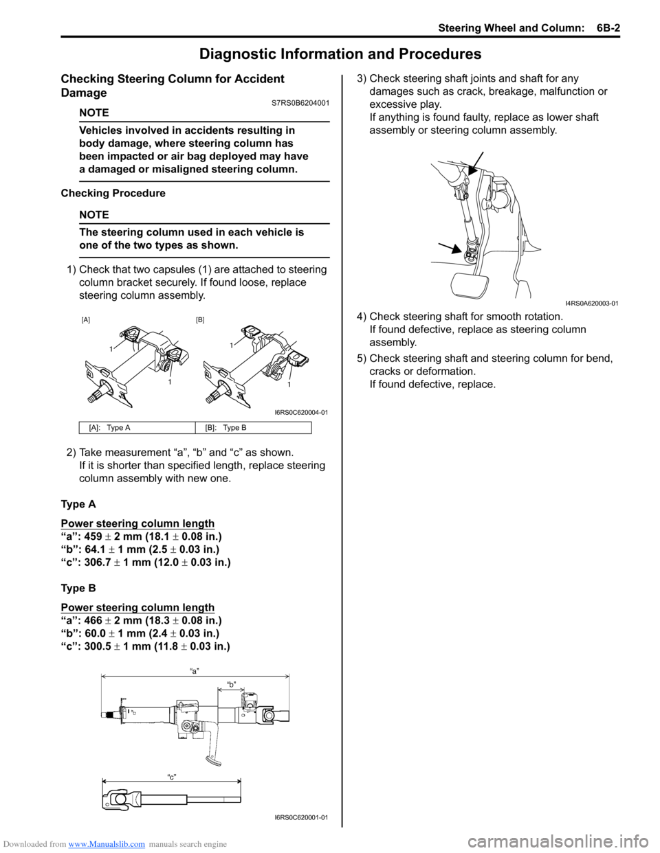
1) Check that two capsules (1) are attached to steering column bracket securely. If found loose, replace
steering column assembly.
2) Take measurement “a”, “b” and “c” as shown. If it is shorter than spec ified length, replace steering
column assembly with new one.
Ty p e A
Power steering column length
“a”: 459 ± 2 mm (18.1 ± 0.08 in.)
“b”: 64.1 ± 1 mm (2.5 ± 0.03 in.)
“c”: 306.7 ± 1 mm (12.0 ± 0.03 in.)
Ty p e B
Power steering column length
“a”: 466 ± 2 mm (18.3 ± 0.08 in.)
“b”: 60.0 ± 1 mm (2.4 ± 0.03 in.)
“c”: 300.5 ± 1 mm (11.8 ± 0.03 in.) 3) Check steering shaft joints and shaft for any
damages such as crack, breakage, malfunction or
excessive play.
If anything is found faulty, replace as lower shaft
assembly or steering column assembly.
4) Check steering shaft for smooth rotation. If found defective, replace as steering column
assembly.
5) Check steering shaft and steering column for bend, cracks or deformation.
If found defective, replace.
[A]: Type A [B]: Type B
[A] [B]
1
1
1
1
I6RS0C620004-01
I6RS0C620001-01
I4RS0A620003-01
Page 879 of 1496
Downloaded from www.Manualslib.com manuals search engine Steering Wheel and Column: 6B-8
Installation
CAUTION!
After tightening steering column mounting
nuts, shaft joint bolts should be tightened.
Wrong tightening order could cause a
damage to shaft joint.
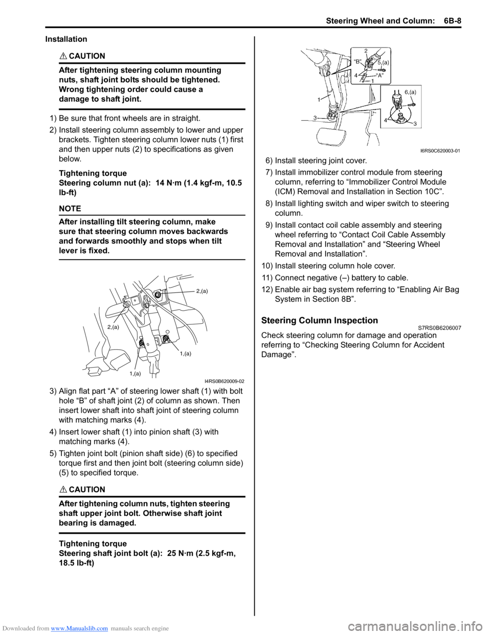
1) Be sure that front wheels are in straight.
2) Install steering column assembly to lower and upper brackets. Tighten steering column lower nuts (1) first
and then upper nuts (2) to specifications as given
below.
Tightening torque
Steering column nut (a): 14 N·m (1.4 kgf-m, 10.5
lb-ft)
NOTE
After installing tilt steering column, make
sure that steering column moves backwards
and forwards smoothly and stops when tilt
lever is fixed.
3) Align flat part “A” of stee ring lower shaft (1) with bolt
hole “B” of shaft joint (2) of column as shown. Then
insert lower shaft into shaf t joint of steering column
with matching marks (4).
4) Insert lower shaft (1) into pinion shaft (3) with matching marks (4).
5) Tighten joint bolt (pinion shaft side) (6) to specified torque first and then joint bolt (steering column side)
(5) to specified torque.
CAUTION!
After tightening column nuts, tighten steering
shaft upper joint bolt. Otherwise shaft joint
bearing is damaged.
Tightening torque
Steering shaft joint bolt (a): 25 N·m (2.5 kgf-m,
18.5 lb-ft) 6) Install steering joint cover.
7) Install immobilizer cont
rol module from steering
column, referring to “Immo bilizer Control Module
(ICM) Removal and Installation in Section 10C”.
8) Install lighting switch and wiper switch to steering column.
9) Install contact coil cable assembly and steering wheel referring to “Conta ct Coil Cable Assembly
Removal and Installation” and “Steering Wheel
Removal and Installation”.
10) Install steering column hole cover. 11) Connect negative (–) battery to cable.
12) Enable air bag system refe rring to “Enabling Air Bag
System in Section 8B”.
Steering Column InspectionS7RS0B6206007
Check steering column for damage and operation
referring to “Checking Steering Column for Accident
Damage”.
2,(a)
1,(a)
1,(a)
2,(a)
I4RS0B620009-02
I6RS0C620003-01
Page 887 of 1496
Downloaded from www.Manualslib.com manuals search engine Power Assisted Steering System: 6C-5
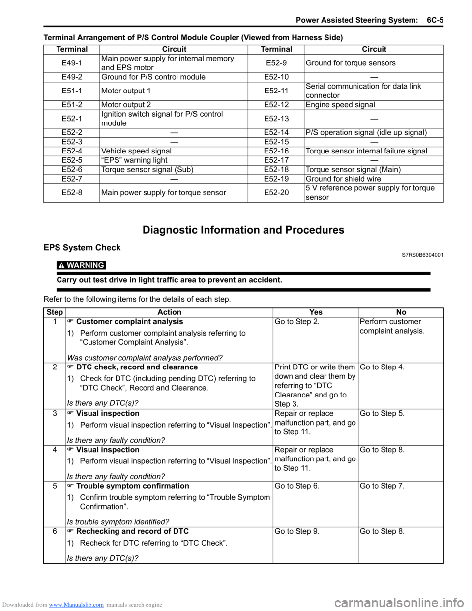
Terminal Arrangement of P/S Control Module Coupler (Viewed from Harness Side)
Diagnostic Information and Procedures
EPS System CheckS7RS0B6304001
WARNING!
Carry out test drive in light traffic area to prevent an accident.
Refer to the following items for the details of each step.Terminal Circuit Terminal Circuit
E49-1 Main power supply for internal memory
and EPS motor E52-9 Ground for torque sensors
E49-2 Ground for P/S control module E52-10 —
E51-1 Motor output 1 E52-11 Serial communication for data link
connector
E51-2 Motor output 2 E52-12 Engine speed signal
E52-1 Ignition switch signal for P/S control
module E52-13 —
E52-2 — E52-14 P/S operation signal (idle up signal)
E52-3 — E52-15 —
E52-4 Vehicle speed signal E52-16 Torque sensor internal failure signal
E52-5 “EPS” warning light E52-17 —
E52-6 Torque sensor signal (Sub) E52-18 Torque sensor signal (Main)
E52-7 — E52-19 Ground for shield wire
E52-8 Main power supply for torque sensor E52-20 5 V reference power supply for torque
sensor
Step
Action YesNo
1 �) Customer complaint analysis
1) Perform customer complaint analysis referring to “Customer Complaint Analysis”.
Was customer complaint analysis performed? Go to Step 2.
Perform customer
complaint analysis.
2 �) DTC check, record and clearance
1) Check for DTC (including pending DTC) referring to “DTC Check”, Record and Clearance.
Is there any DTC(s)? Print DTC or write them
down and clear them by
referring to “DTC
Clearance” and go to
St ep 3 .Go to Step 4.
3 �) Visual inspection
1) Perform visual inspection referring to “Visual Inspection”.
Is there any faulty condition? Repair or replace
malfunction part, and go
to Step 11.
Go to Step 5.
4 �) Visual inspection
1) Perform visual inspection referring to “Visual Inspection”.
Is there any faulty condition? Repair or replace
malfunction part, and go
to Step 11.
Go to Step 8.
5 �) Trouble symptom confirmation
1) Confirm trouble symptom referring to “Trouble Symptom Confirmation”.
Is trouble symptom identified? Go to Step 6.
Go to Step 7.
6 �) Rechecking and record of DTC
1) Recheck for DTC referring to “DTC Check”.
Is there any DTC(s)? Go to Step 9.
Go to Step 8.
Page 888 of 1496
Downloaded from www.Manualslib.com manuals search engine 6C-6 Power Assisted Steering System:
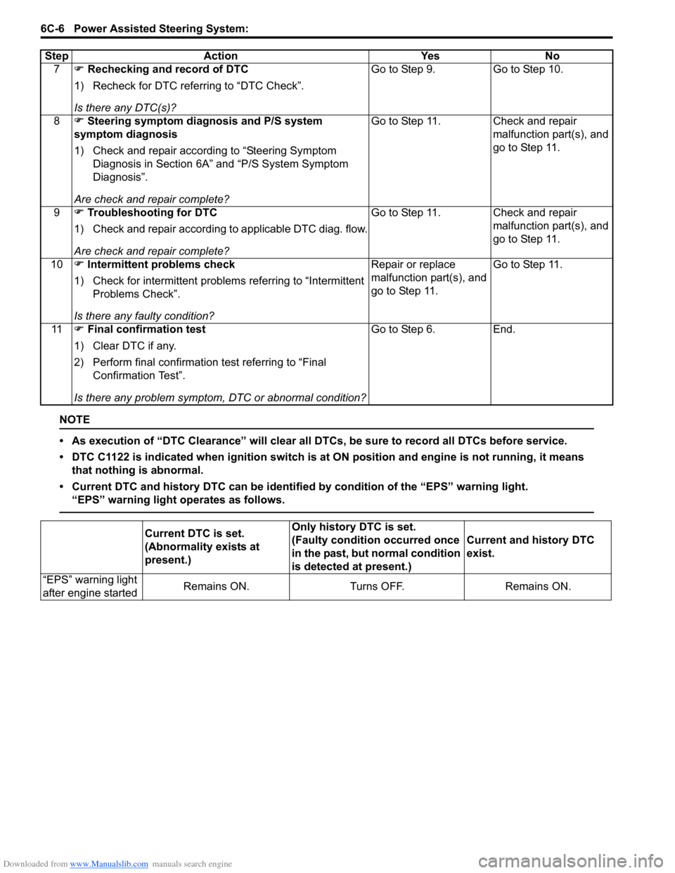
NOTE
• As execution of “DTC Clearance” will clear all DTCs, be sure to record all DTCs before service.
• DTC C1122 is indicated when ignition switch is at ON position and engine is not running, it means
that nothing is abnormal.
• Current DTC and history DTC ca n be identified by condition of the “EPS” warning light.
“EPS” warning light operates as follows.
7 �) Rechecking and record of DTC
1) Recheck for DTC referring to “DTC Check”.
Is there any DTC(s)? Go to Step 9. Go to Step 10.
8 �) Steering symptom diagnosis and P/S system
symptom diagnosis
1) Check and repair according to “Steering Symptom Diagnosis in Section 6A” and “P/S System Symptom
Diagnosis”.
Are check and repair complete? Go to Step 11. Check and repair
malfunction part(s), and
go to Step 11.
9 �) Troubleshooting for DTC
1) Check and repair according to applicable DTC diag. flow.
Are check and repair complete? Go to Step 11. Check and repair
malfunction part(s), and
go to Step 11.
10 �) Intermittent problems check
1) Check for intermittent problems referring to “Intermittent Problems Check”.
Is there any faulty condition? Repair or replace
malfunction part(s), and
go to Step 11.
Go to Step 11.
11 �) Final confirmation test
1) Clear DTC if any.
2) Perform final confirmation test referring to “Final Confirmation Test”.
Is there any problem symptom, DTC or abnormal condition? Go to Step 6. End.
Step Action Yes No
Current DTC is set.
(Abnormality exists at
present.)
Only history DTC is set.
(Faulty condition occurred once
in the past, but normal condition
is detected at present.)
Current and history DTC
exist.
“EPS” warning light
after engine started Remains ON. Turns OFF. Remains ON.