Engine cooling SUZUKI SWIFT 2008 2.G Service Repair Manual
[x] Cancel search | Manufacturer: SUZUKI, Model Year: 2008, Model line: SWIFT, Model: SUZUKI SWIFT 2008 2.GPages: 1496, PDF Size: 34.44 MB
Page 371 of 1496
Downloaded from www.Manualslib.com manuals search engine Engine Cooling System: 1F-8
Thermostat Removal and InstallationS7RS0B1606007
Removal1) Drain coolant referring to “Cooling System Draining”.
2) Remove intake manifold referring to “Intake Manifold Removal and Installa tion in Section 1D”.
3) Remove generator referring to “Generator Dismounting and Remounting in Section 1J”.
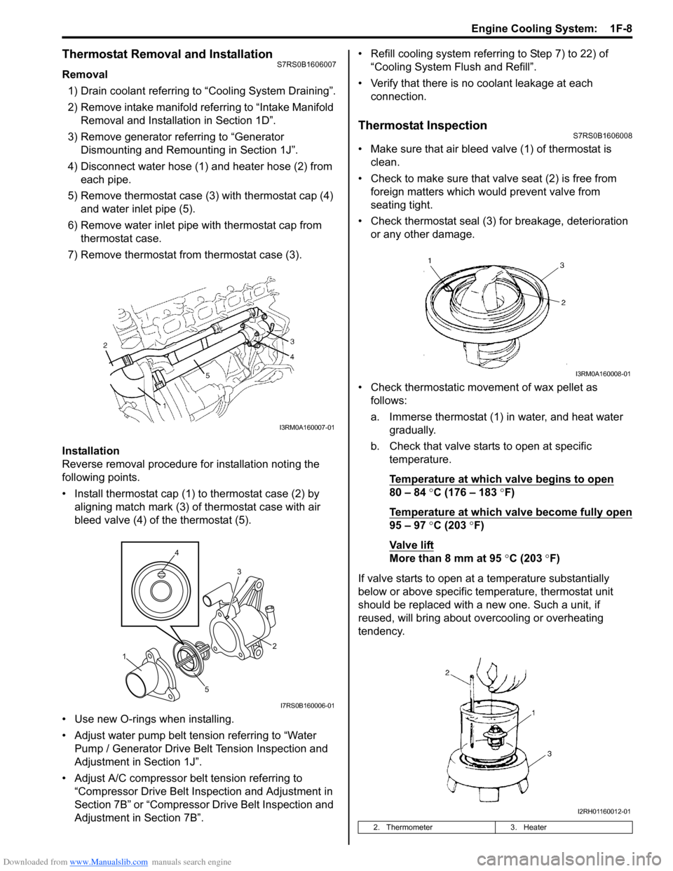
4) Disconnect water hose (1) and heater hose (2) from each pipe.
5) Remove thermostat case (3) with thermostat cap (4)
and water inlet pipe (5).
6) Remove water inlet pipe with thermostat cap from thermostat case.
7) Remove thermostat from thermostat case (3).
Installation
Reverse removal procedure for installation noting the
following points.
• Install thermostat cap (1) to thermostat case (2) by aligning match mark (3) of thermostat case with air
bleed valve (4) of the thermostat (5).
• Use new O-rings when installing.
• Adjust water pump belt tension referring to “Water Pump / Generator Drive Belt Tension Inspection and
Adjustment in Section 1J”.
• Adjust A/C compressor belt tension referring to “Compressor Drive Belt Inspection and Adjustment in
Section 7B” or “Compressor Drive Belt Inspection and
Adjustment in Section 7B”. • Refill cooling system referrin
g to Step 7) to 22) of
“Cooling System Flush and Refill”.
• Verify that there is no coolant leakage at each connection.
Thermostat InspectionS7RS0B1606008
• Make sure that air bleed valve (1) of thermostat is clean.
• Check to make sure that va lve seat (2) is free from
foreign matters which would prevent valve from
seating tight.
• Check thermostat seal (3) for breakage, deterioration or any other damage.
• Check thermostatic movement of wax pellet as follows:
a. Immerse thermostat (1) in water, and heat water gradually.
b. Check that valve starts to open at specific temperature.
Temperature at which valve begins to open
80 – 84 °C (176 – 183 °F)
Temperature at which valve become fully open
95 – 97 °C (203 °F)
Va l v e l i ft
More than 8 mm at 95 °C (203 ° F)
If valve starts to open at a temperature substantially
below or above specific temperature, thermostat unit
should be replaced with a new one. Such a unit, if
reused, will bring about ov ercooling or overheating
tendency.
I3RM0A160007-01
4
5 3
1 2
I7RS0B160006-01
2. Thermometer
3. Heater
I3RM0A160008-01
I2RH01160012-01
Page 372 of 1496
Downloaded from www.Manualslib.com manuals search engine 1F-9 Engine Cooling System:
Radiator Cooling Fan Motor On-Vehicle
Inspection
S7RS0B1606009
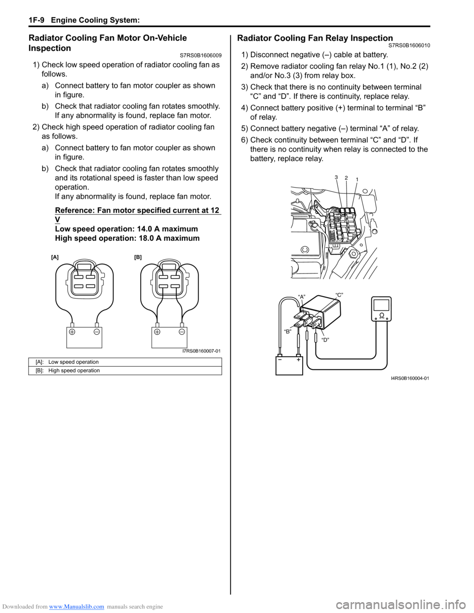
1) Check low speed operation of radiator cooling fan as follows.
a) Connect battery to fan motor coupler as shown in figure.
b) Check that radiator cooling fan rotates smoothly. If any abnormality is found, replace fan motor.
2) Check high speed operation of radiator cooling fan as follows.
a) Connect battery to fan motor coupler as shown in figure.
b) Check that radiator cooling fan rotates smoothly and its rotational speed is faster than low speed
operation.
If any abnormality is found, replace fan motor.
Reference: Fan motor sp ecified current at 12
V
Low speed operation: 14.0 A maximum
High speed operation: 18.0 A maximum
Radiator Cooling Fan Relay InspectionS7RS0B1606010
1) Disconnect negative (–) cable at battery.
2) Remove radiator cooling fa n relay No.1 (1), No.2 (2)
and/or No.3 (3) from relay box.
3) Check that there is no continuity between terminal “C” and “D”. If there is continuity, replace relay.
4) Connect battery positive (+ ) terminal to terminal “B”
of relay.
5) Connect battery negative (–) terminal “A” of relay.
6) Check continuity between terminal “C” and “D”. If there is no continuity when relay is connected to the
battery, replace relay.
[A]: Low speed operation
[B]: High speed operation
[A] [B]
I7RS0B160007-01
“D”
“B” “A”
“C”
1
2
3
I4RS0B160004-01
Page 373 of 1496
Downloaded from www.Manualslib.com manuals search engine Engine Cooling System: 1F-10
Radiator Cooling Fan Removal and InstallationS7RS0B1606011
Removal1) Disconnect negative (–) cable at battery.
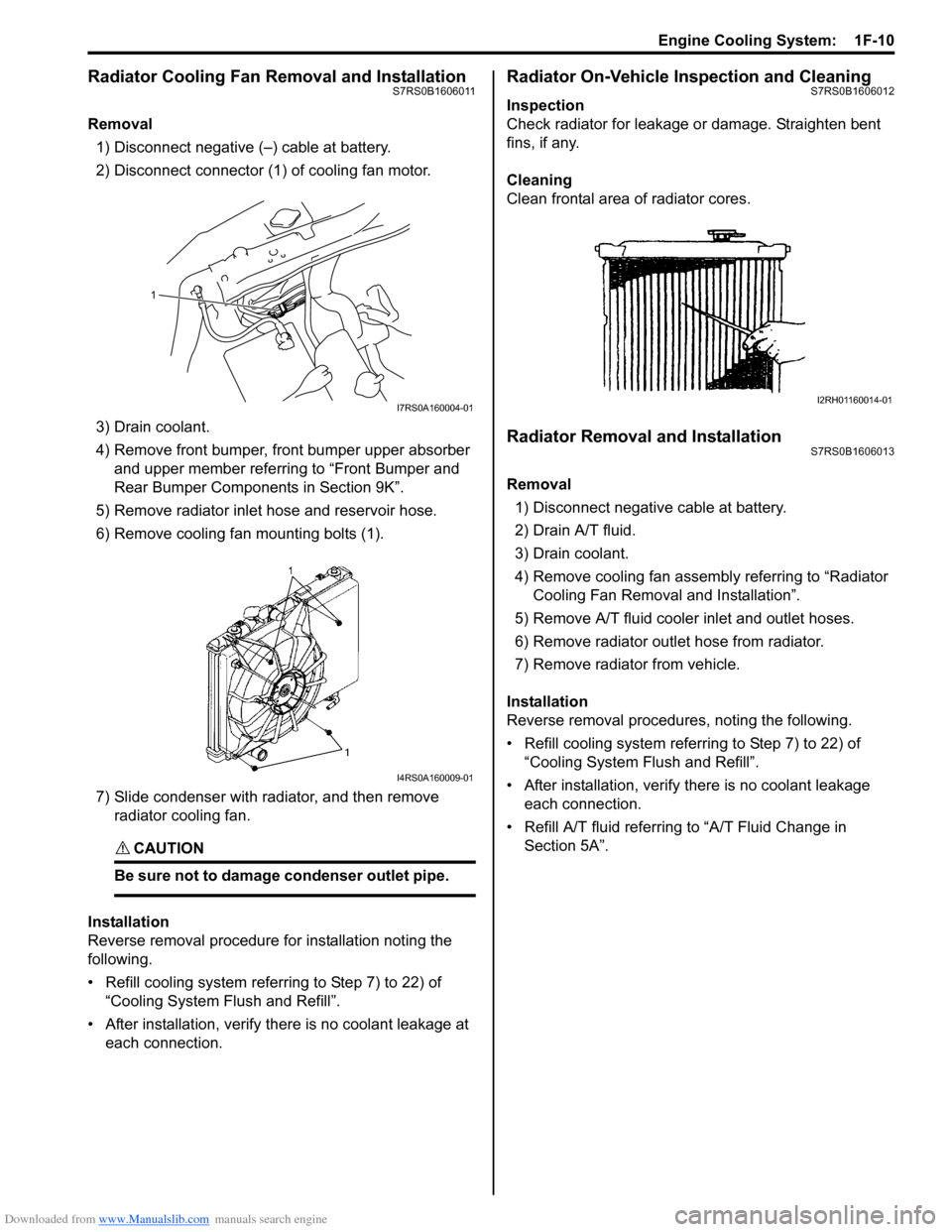
2) Disconnect connector (1) of cooling fan motor.
3) Drain coolant.
4) Remove front bumper, front bumper upper absorber and upper member referring to “Front Bumper and
Rear Bumper Componen ts in Section 9K”.
5) Remove radiator inlet hose and reservoir hose.
6) Remove cooling fan mounting bolts (1).
7) Slide condenser with radiator, and then remove radiator cooling fan.
CAUTION!
Be sure not to damage condenser outlet pipe.
Installation
Reverse removal procedure for installation noting the
following.
• Refill cooling system referring to Step 7) to 22) of “Cooling System Fl ush and Refill”.
• After installation, verify there is no coolant leakage at each connection.
Radiator On-Vehicle Inspection and CleaningS7RS0B1606012
Inspection
Check radiator for leakage or damage. Straighten bent
fins, if any.
Cleaning
Clean frontal area of radiator cores.
Radiator Removal and InstallationS7RS0B1606013
Removal
1) Disconnect negative cable at battery.
2) Drain A/T fluid.
3) Drain coolant.
4) Remove cooling fan assemb ly referring to “Radiator
Cooling Fan Removal and Installation”.
5) Remove A/T fluid cooler inlet and outlet hoses.
6) Remove radiator outlet hose from radiator.
7) Remove radiator from vehicle.
Installation
Reverse removal procedures, noting the following.
• Refill cooling system referrin g to Step 7) to 22) of
“Cooling System Flush and Refill”.
• After installation, verify there is no coolant leakage each connection.
• Refill A/T fluid referring to “A/T Fluid Change in
Section 5A”.
1
I7RS0A160004-01
I4RS0A160009-01
I2RH01160014-01
Page 374 of 1496
Downloaded from www.Manualslib.com manuals search engine 1F-11 Engine Cooling System:
Water Pump Removal and InstallationS7RS0B1606014
Removal1) Disconnect negative cable at battery.
2) Drain coolant.
3) Remove water pump / generator drive belt referring to “Water Pump / Generator Drive Belt Removal and
Installation in Section 1J”.
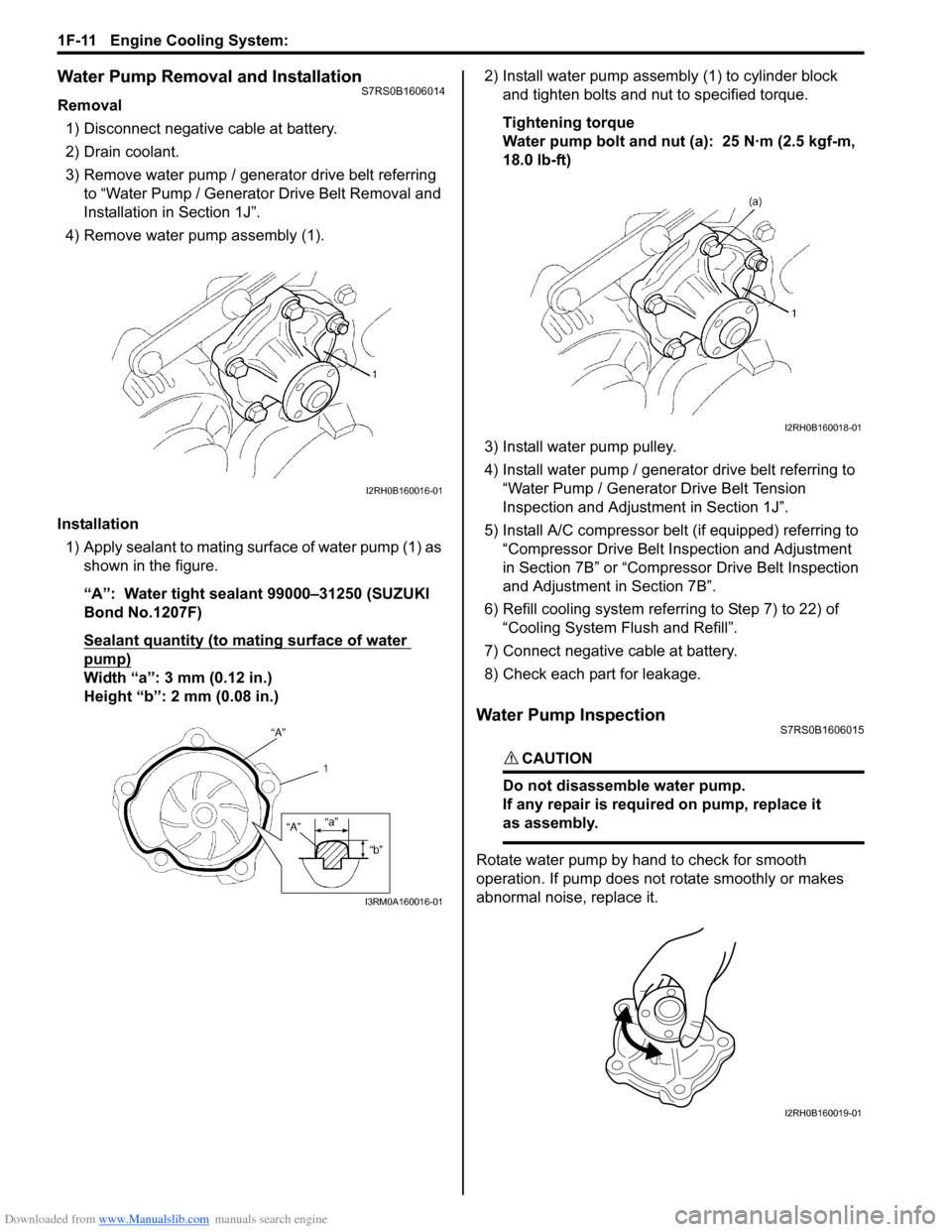
4) Remove water pump assembly (1).
Installation 1) Apply sealant to mating surface of water pump (1) as shown in the figure.
“A”: Water tight sealant 99000–31250 (SUZUKI
Bond No.1207F)
Sealant quantity (to mating surface of water
pump)
Width “a”: 3 mm (0.12 in.)
Height “b”: 2 mm (0.08 in.) 2) Install water pump assemb
ly (1) to cylinder block
and tighten bolts and nut to specified torque.
Tightening torque
Water pump bolt and nut (a): 25 N·m (2.5 kgf-m,
18.0 lb-ft)
3) Install water pump pulley.
4) Install water pump / generator drive belt referring to “Water Pump / Generator Drive Belt Tension
Inspection and Adjustment in Section 1J”.
5) Install A/C compressor belt (if equipped) referring to “Compressor Drive Belt Inspection and Adjustment
in Section 7B” or “Compressor Drive Belt Inspection
and Adjustment in Section 7B”.
6) Refill cooling system referri ng to Step 7) to 22) of
“Cooling System Flush and Refill”.
7) Connect negative cable at battery.
8) Check each part for leakage.
Water Pump InspectionS7RS0B1606015
CAUTION!
Do not disassemble water pump.
If any repair is requir ed on pump, replace it
as assembly.
Rotate water pump by hand to check for smooth
operation. If pump does not rotate smoothly or makes
abnormal noise, replace it.
I2RH0B160016-01
I3RM0A160016-01
I2RH0B160018-01
I2RH0B160019-01
Page 375 of 1496
Downloaded from www.Manualslib.com manuals search engine Engine Cooling System: 1F-12
Specifications
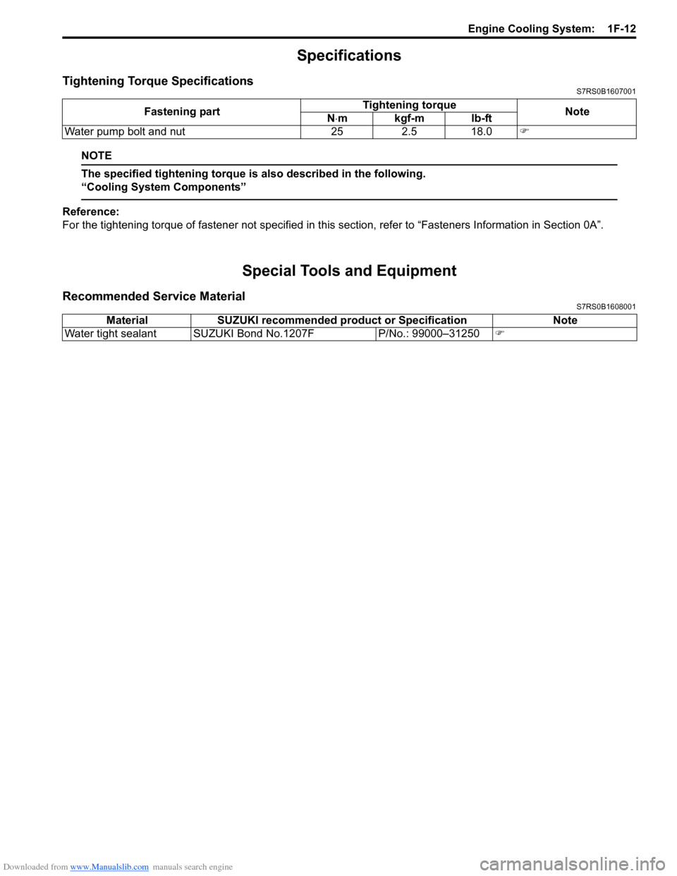
Tightening Torque SpecificationsS7RS0B1607001
NOTE
The specified tightening torque is also described in the following.
“Cooling System Components”
Reference:
For the tightening torque of fastener not specified in this section, refer to “Fasteners Information in Section 0A”.
Special Tools and Equipment
Recommended Service MaterialS7RS0B1608001
Fastening part Tightening torque
Note
N ⋅mkgf-mlb-ft
Water pump bolt and nut 25 2.5 18.0 �)
MaterialSUZUKI recommended product or Specification Note
Water tight sealant SUZUKI Bond No.1207F P/No.: 99000–31250�)
Page 469 of 1496
Downloaded from www.Manualslib.com manuals search engine Wheels and Tires: 2D-2
Lower than recommended pressure can cause:
• Tire squeal on turns
• Hard Steering
• Rapid and uneven wear on the edges of the tread
• Tire rim bruises and rupture
• Tire cord breakage
• High tire temperature
• Reduced handling
• High fuel consumption
Replacement Tires
When replacement is necessary, the original equipment
type tire should be used. Refer to the Tire Placard.
Replacement tires should be of the same size, load
range and construction as those originally on the vehicle.
Use of any other size or type tire may affect ride,
handling, speedometer / odometer calibration, vehicle
ground clearance and tire or snow chain clearance to the
body and chassis.
It is recommended that new tires be installed in pairs on
the same axle. If necessary to replace only one tire, it
should be paired with the tire having the most tread, to
equalize braking traction.
WARNING!
Do not mix different types of tires on the
same vehicle such as radial, bias and bias-
belted tires except in emergencies, because
handling may be seriously affected and may
result in loss of control.
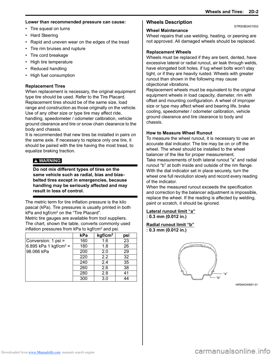
The metric term for tire infl ation pressure is the kilo
pascal (kPa). Tire pressures is usually printed in both
kPa and kgf/cm
2 on the “Tire Placard”.
Metric tire gauges are available from tool suppliers.
The chart, shown the table, converts commonly used
inflation pressures from kPa to kgf/cm
2 and psi.
Wheels DescriptionS7RS0B2401002
Wheel Maintenance
Wheel repairs that use welding, heating, or peening are
not approved. All damaged wheels should be replaced.
Replacement Wheels
Wheels must be replaced if they are bent, dented, have
excessive lateral or radial runout, air leak through welds,
have elongated bolt holes, if lug wheel bolts won’t stay
tight, or if they are heavily rusted. Wheels with greater
runout than shown in the following may cause
objectional vibrations.
Replacement wheels must be equivalent to the original
equipment wheels in load capacity, diameter, rim with
offset and mounting configuration. A wheel of improper
size or type may affect wheel and bearing life, brake
cooling, speedometer / odometer calibration, vehicle
ground clearance and tire clearance to body and
chassis.
How to Measure Wheel Runout
To measure the wheel runout, it is necessary to use an
accurate dial indicator. The tire may be on or off the
wheel. The wheel should be installed to the wheel
balancer of the like for proper measurement.
Take measurements of both lateral runout “a” and radial
runout “b” at both inside an d outside of the rim flange.
With the dial indicator set in place securely, turn the
wheel one full revolution slowly and record every reading
of the indicator.
When the measured runout exceeds the specification
and correction by the balancer adjustment is impossible,
replace the wheel. If the reading is affected by welding,
paint or scratch, it should be ignored.
Lateral runout limit “a”
: 0.3 mm (0.012 in.)
Radial runout limit “b”
: 0.3 mm (0.012 in.)
kPa kgf/cm2psi
Conversion: 1 psi =
6.895 kPa 1 kgf/cm
2 =
98.066 kPa 160 1.6 23
180 1.8 26
200 2.0 29
220 2.2 32
240 2.4 35
260 2.6 38
280 2.8 41
300 3.0 44
I4RS0A240001-01
Page 649 of 1496
Downloaded from www.Manualslib.com manuals search engine Automatic Transmission/Transaxle: 5A-5
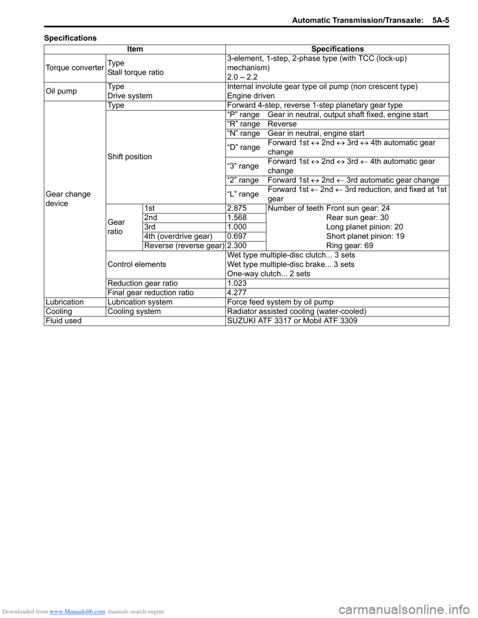
SpecificationsItem Specifications
Torque converter Ty p e
Stall torque ratio 3-element, 1-step, 2-phase type (with TCC (lock-up)
mechanism)
2.0 – 2.2
Oil pump Ty p e
Drive system Internal involute gear type oil pump (non crescent type)
Engine driven
Gear change
device Type Forward 4-step, reverse 1-step planetary gear type
Shift position
“P” range Gear in neutral, output shaft fixed, engine start
“R” range Reverse
“N” range Gear in neutral, engine start
“D” range
Forward 1st
↔ 2nd ↔ 3rd ↔ 4th automatic gear
change
“3” range Forward 1st
↔ 2nd ↔ 3rd ← 4th automatic gear
change
“2” range Forward 1st ↔ 2nd ← 3rd automatic gear change
“L” range Forward 1st
← 2nd ← 3rd reduction, and fixed at 1st
gear
Gear
ratio 1st 2.875 Number of teeth Front sun gear: 24
2nd 1.568 Rear sun gear: 30
3rd 1.000 Long planet pinion: 20
4th (overdrive gear) 0.697 Short planet pinion: 19
Reverse (reverse gear) 2.300 Ring gear: 69
Control elements Wet type multiple-disc clutch... 3 sets
Wet type multiple-d
isc brake... 3 sets
One-way clutch... 2 sets
Reduction gear ratio 1.023
Final gear reduction ratio 4.277
Lubrication Lubrication system Force feed system by oil pump
Cooling Cooling system Radiator assisted cooling (water-cooled)
Fluid used SUZUKI ATF 3317 or Mobil ATF 3309
Page 824 of 1496
Downloaded from www.Manualslib.com manuals search engine 5B-10 Manual Transmission/Transaxle:
16) Remove engine under covers.
17) Support transaxle with transmission jack.
18) Remove transaxle to engine bolts and nut of lower side.
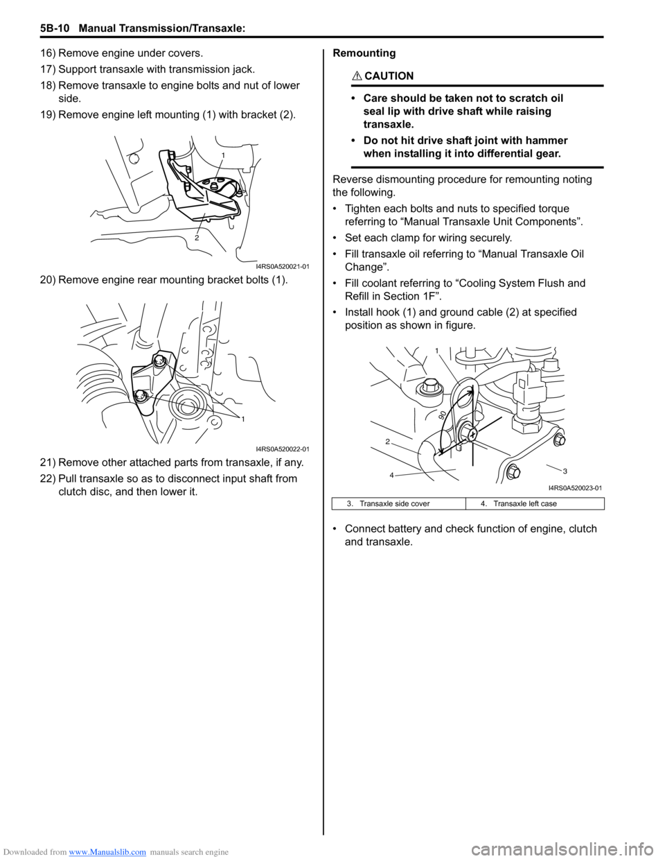
19) Remove engine left mounting (1) with bracket (2).
20) Remove engine rear mounting bracket bolts (1).
21) Remove other attached parts from transaxle, if any.
22) Pull transaxle so as to disconnect input shaft from clutch disc, and then lower it. Remounting
CAUTION!
• Care should be taken not to scratch oil
seal lip with drive shaft while raising
transaxle.
• Do not hit drive shaft joint with hammer when installing it into differential gear.
Reverse dismounting procedure for remounting noting
the following.
• Tighten each bolts and nuts to specified torque referring to “Manual Transaxle Unit Components”.
• Set each clamp for wiring securely.
• Fill transaxle oil referring to “Manual Transaxle Oil
Change”.
• Fill coolant referring to “Cooling System Flush and
Refill in Section 1F”.
• Install hook (1) and ground cable (2) at specified position as shown in figure.
• Connect battery and check function of engine, clutch
and transaxle.
1
2
I4RS0A520021-01
1
I4RS0A520022-01
3. Transaxle side cover 4. Transaxle left case
90
1
2 3
4
I4RS0A520023-01
Page 954 of 1496
Downloaded from www.Manualslib.com manuals search engine 7B-6 Air Conditioning System: Manual Type
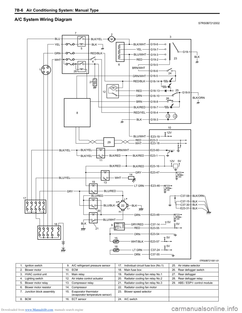
A/C System Wiring DiagramS7RS0B7212002
BLK/REDBLK/RED
BLK/YELBLK/YEL
BLK/YEL
BRN/WHT
12V5V
5V 5V
5V11
E23-1
E23-60
BLK/REDBLK/REDE23-16
E23-57WHT/BLK
9
13
E23-55C37-14GRY/REDRED
BLK
ORN
E23-47 GRY
WHTBLU/YEL
RED/BLK
14 3
1
15
5
7
BLK
2
M
12VBLU/WHTE23-19
C37-24
C37-55ORN
5V
LT GRN16
G18-3
G18-4
G18-7
G18-8
G18-10
G18-13
G18-5
G18-6
G19-5
G19-2
G19-3
G19-7
G19-6
G19-1
G18-9
G18-14
BLK/WHT
YEL
BLU/WHT
RED
BRN/WHT
GRN/WHT
RED/BLK
RED
GRN
BRN
BLK/RED
RED/YEL
BLK
BLK/YEL
BLK/ORN
4
6
12
10
M
E23-54
REDWHTE23-3E23-18
17 18
LT GRNE23-46
L+
L–
H–
H
+
BLU/RED
BLK
BLU/WHTBLK
BLU/BLK
20
GRN
GRY
E23-48
19
21
22
BLU/REDC37-58
C37-15 C37-30
BLK/ORN
BLKBLKE23-31 BLK
BLU
YEL
GRN
WHT
23
24
26 25
28
27
8
29
I7RS0B721001-01
1. Ignition switch
9. A/C refrigerant pressure sensor 17. I ndividual circuit fuse box (No.1) 25. Air intake selector
2. Blower motor 10. ECM 18. Main fuse box 26. Rear defogger switch
3. HVAC control unit 11. Main relay 19. Radiator cooling fan relay No.1 27. Rear defogger
4. Lighting switch 12. Air intake control actuator 20. Radiator cooling fan relay No.2 28. Rear defogger relay
5. Blower motor relay 13. Compressor relay 21. Radiator cooling fan relay No.3 29. ABS / ESP ® control module
6. Blower motor resistor 14. Compressor 22. Radiator cooling fan motor
7. Junction block assembly 15. Evaporator thermistor (evaporator temperature sensor)23. Blower speed selector
8. BCM 16. ECT sensor 24. A/C switch
Page 955 of 1496
Downloaded from www.Manualslib.com manuals search engine Air Conditioning System: Manual Type 7B-7
Diagnostic Information and Procedures
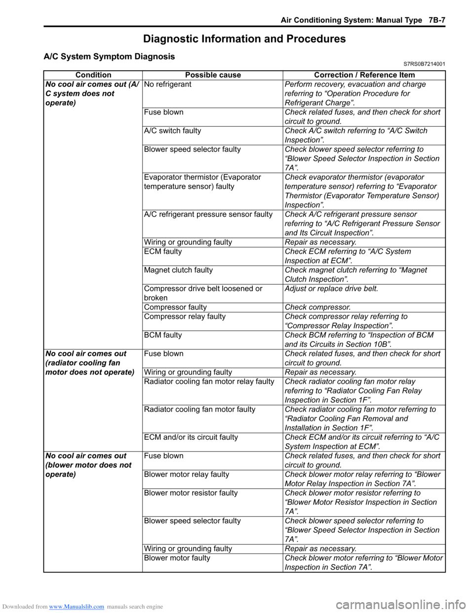
A/C System Symptom DiagnosisS7RS0B7214001
ConditionPossible cause Correction / Reference Item
No cool air comes out (A/
C system does not
operate) No refrigerant
Perform recovery, evacuation and charge
referring to “Operation Procedure for
Refrigerant Charge”.
Fuse blown Check related fuses, and then check for short
circuit to ground.
A/C switch faulty Check A/C switch referring to “A/C Switch
Inspection”.
Blower speed selector faulty Check blower speed selector referring to
“Blower Speed Selector Inspection in Section
7A”.
Evaporator thermistor (Evaporator
temperature sensor) faulty Check evaporator thermistor (evaporator
temperature sensor) referring to “Evaporator
Thermistor (Evaporator Temperature Sensor)
Inspection”.
A/C refrigerant pressure sensor faulty Check A/C refrigerant pressure sensor
referring to “A/C Refrigerant Pressure Sensor
and Its Circuit Inspection”.
Wiring or grounding faulty Repair as necessary.
ECM faulty Check ECM referring to “A/C System
Inspection at ECM”.
Magnet clutch faulty Check magnet clutch referring to “Magnet
Clutch Inspection”.
Compressor drive belt loosened or
broken Adjust or replace drive belt.
Compressor faulty Check compressor.
Compressor relay faulty Check compressor relay referring to
“Compressor Relay Inspection”.
BCM faulty Check BCM referring to “Inspection of BCM
and its Circuits in Section 10B”.
No cool air comes out
(radiator cooling fan
motor does not operate) Fuse blown
Check related fuses, and then check for short
circuit to ground.
Wiring or grounding faulty Repair as necessary.
Radiator cooling fan motor relay faulty Check radiator cooling fan motor relay
referring to “Radiator Cooling Fan Relay
Inspection in Section 1F”.
Radiator cooling fan motor faulty Check radiator cooling fan motor referring to
“Radiator Cooling Fan Removal and
Installation in Section 1F”.
ECM and/or its circuit faulty Check ECM and/or its circuit referring to “A/C
System Inspection at ECM”.
No cool air comes out
(blower motor does not
operate) Fuse blown
Check related fuses, and then check for short
circuit to ground.
Blower motor relay faulty Check blower motor relay referring to “Blower
Motor Relay Inspection in Section 7A”.
Blower motor resistor faulty Check blower motor resistor referring to
“Blower Motor Resistor Inspection in Section
7A”.
Blower speed selector faulty Check blower speed selector referring to
“Blower Speed Selector Inspection in Section
7A”.
Wiring or grounding faulty Repair as necessary.
Blower motor faulty Check blower motor referring to “Blower Motor
Inspection in Section 7A”.