2008 SUZUKI SWIFT 2008 2.G Service Workshop Manual
[x] Cancel search | Manufacturer: SUZUKI, Model Year: 2008, Model line: SWIFT, Model: SUZUKI SWIFT 2008 2.GPages: 1496, PDF Size: 34.44 MB
Page 1 of 1496
Downloaded from www.Manualslib.com manuals search engine Suzuki Swift Sport (RS416)
2004-2008 Service/Repair Manual
This Service Manual has been prepared with the latest service information available at the time
of publication. It is subdivided into various group categories and each section contains diagnostic,
disassembly, repair and installation procedures along with complete specifications and tightening
references. Please read this manual carefully before proceeding, as incorrect service procedures
may result in injury or death to service personnel or to the operator’s of the vehicle.
Page 829 of 1496
Downloaded from www.Manualslib.com manuals search engine Manual Transmission/Transaxle: 5B-15
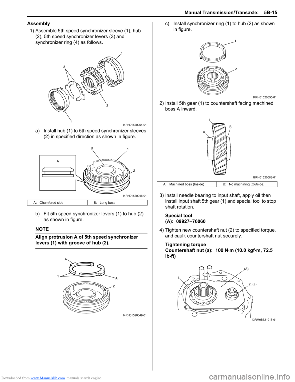
Assembly1) Assemble 5th speed synchronizer sleeve (1), hub (2), 5th speed synchronizer levers (3) and
synchronizer ring (4) as follows.
a) Install hub (1) to 5th speed synchronizer sleeves (2) in specified direction as shown in figure.
b) Fit 5th speed synchronizer levers (1) to hub (2) as shown in figure.
NOTE
Align protrusion A of 5th speed synchronizer
levers (1) with groove of hub (2).
c) Install synchronizer ring (1) to hub (2) as shown in figure.
2) Install 5th gear (1) to countershaft facing machined boss A inward.
3) Install needle bearing to input shaft, apply oil then install input shaft 5th gear (1) and special tool to stop
shaft rotation.
Special tool
(A): 09927–76060
4) Tighten new countershaft nut (2) to specified torque, and caulk countershaft nut securely.
Tightening torque
Countershaft nut (a): 100 N·m (10.0 kgf-m, 72.5
lb-ft)
A: Chamfered side B: Long boss
I4RH01520054-01
1
2
B
A
I4RH01520048-01
1A
2
A
I4RH01520049-01
A: Machined boss (Inside)
B: No machining (Outside)
1
2
I4RH01520055-01
I2RH01520088-01
1
(A)
2, (a)
I3RM0B521016-01
Page 832 of 1496
Downloaded from www.Manualslib.com manuals search engine 5B-18 Manual Transmission/Transaxle:
18) Remove differential bearing shim.
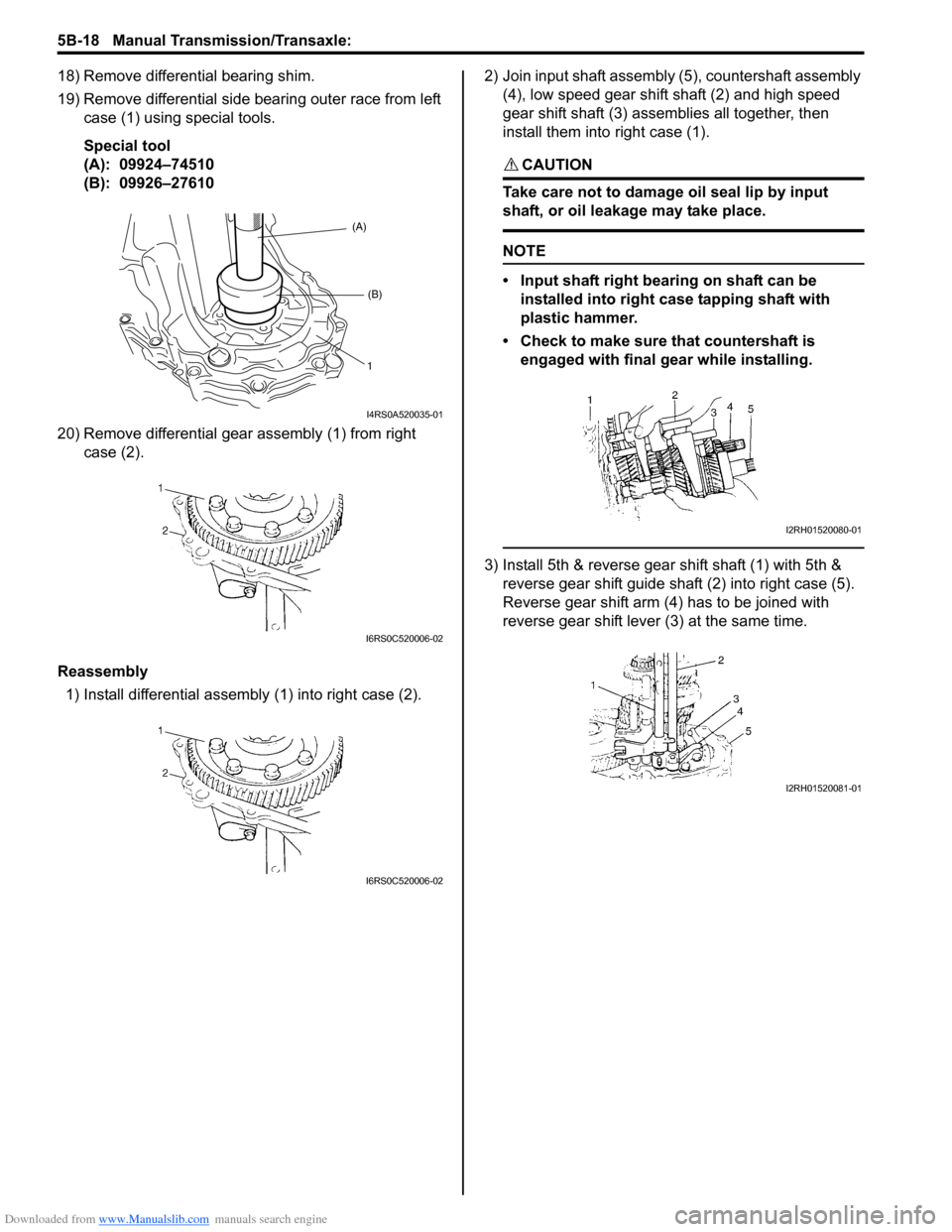
19) Remove differential side bearing outer race from left case (1) using special tools.
Special tool
(A): 09924–74510
(B): 09926–27610
20) Remove differential gear assembly (1) from right case (2).
Reassembly 1) Install differential assembly (1) into right case (2). 2) Join input shaft assembly (5), countershaft assembly
(4), low speed gear shift shaft (2) and high speed
gear shift shaft (3) assemblies all together, then
install them into right case (1).
CAUTION!
Take care not to damage oil seal lip by input
shaft, or oil leakage may take place.
NOTE
• Input shaft right bearing on shaft can be
installed into right case tapping shaft with
plastic hammer.
• Check to make sure that countershaft is engaged with final g ear while installing.
3) Install 5th & reverse gear shift shaft (1) with 5th &
reverse gear shift guide shaft (2) into right case (5).
Reverse gear shift arm (4) has to be joined with
reverse gear shift lever (3) at the same time.
(A)
(B)
1
I4RS0A520035-01
I6RS0C520006-02
I6RS0C520006-02
I2RH01520080-01
I2RH01520081-01
Page 835 of 1496
Downloaded from www.Manualslib.com manuals search engine Manual Transmission/Transaxle: 5B-21
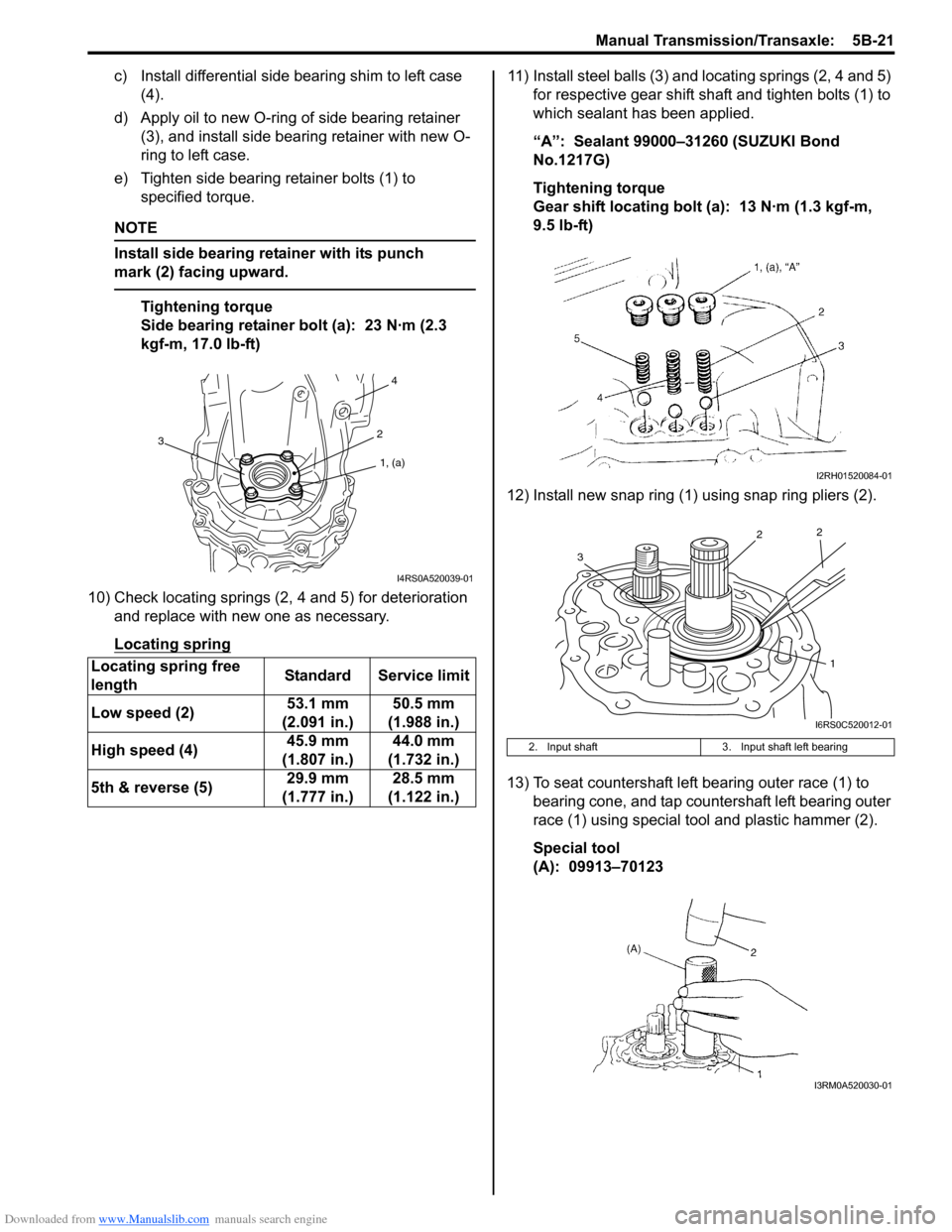
c) Install differential side bearing shim to left case (4).
d) Apply oil to new O-ring of side bearing retainer (3), and install side bea ring retainer with new O-
ring to left case.
e) Tighten side bearing retainer bolts (1) to specified torque.
NOTE
Install side bearing retainer with its punch
mark (2) facing upward.
Tightening torque
Side bearing retainer bolt (a): 23 N·m (2.3
kgf-m, 17.0 lb-ft)
10) Check locating springs (2, 4 and 5) for deterioration and replace with new one as necessary.
Locating spring
11) Install steel balls (3) and locating springs (2, 4 and 5) for respective gear shift shaft and tighten bolts (1) to
which sealant has been applied.
“A”: Sealant 99000–31260 (SUZUKI Bond
No.1217G)
Tightening torque
Gear shift locating bolt (a): 13 N·m (1.3 kgf-m,
9.5 lb-ft)
12) Install new snap ring (1) using snap ring pliers (2).
13) To seat countershaft left bearing outer race (1) to bearing cone, and tap countershaft left bearing outer
race (1) using special tool and plastic hammer (2).
Special tool
(A): 09913–70123
Locating spring free
length
Standard Service limit
Low speed (2) 53.1 mm
(2.091 in.) 50.5 mm
(1.988 in.)
High speed (4) 45.9 mm
(1.807 in.) 44.0 mm
(1.732 in.)
5th & reverse (5) 29.9 mm
(1.777 in.) 28.5 mm
(1.122 in.)
1, (a)
2
4
3
I4RS0A520039-01
2. Input shaft 3. Input shaft left bearing
I2RH01520084-01
1
2
2
3
I6RS0C520012-01
I3RM0A520030-01
Page 848 of 1496
Downloaded from www.Manualslib.com manuals search engine 5B-34 Manual Transmission/Transaxle:
Assembly
Judging from abnormality noted before disassembly and
what is found through visual check of component parts
after disassembly, prepare replacing parts and proceed
to reassembly. Make sure that all parts are clean.
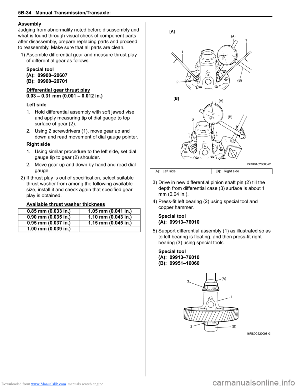
1) Assemble differential gear and measure thrust play
of differential gear as follows.
Special tool
(A): 09900–20607
(B): 09900–20701
Differential gear thrust play
0.03 – 0.31 mm (0.001 – 0.012 in.)
Left side
1. Hold differential assembly with soft jawed vise and apply measuring tip of dial gauge to top
surface of gear (2).
2. Using 2 screwdrivers (1), move gear up and down and read movement of dial gauge pointer.
Right side
1. Using similar procedure to the left side, set dial gauge tip to gear (2) shoulder.
2. Move gear up and down by hand and read dial gauge.
2) If thrust play is out of sp ecification, select suitable
thrust washer from among the following available
size, install it and check again that specified gear
play is obtained.
Available thrust washer thickness
3) Drive in new differential pinion shaft pin (2) till the depth from differential case (3) surface is about 1
mm (0.04 in.).
4) Press-fit left bearing (2) using special tool and copper hammer.
Special tool
(A): 09913–76010
5) Support differential assembly (1) as illustrated so as to left bearing is floating , and then press-fit right
bearing (3) using special tools.
Special tool
(A): 09913–76010
(B): 09951–16060
0.85 mm (0.033 in.) 1.05 mm (0.041 in.)
0.90 mm (0.035 in.) 1.10 mm (0.043 in.)
0.95 mm (0.037 in.) 1.15 mm (0.045 in.)
1.00 mm (0.039 in.)
[A]: Left side
[B]: Right side
I3RH0A520083-01
1
(A)
3
2 (B)
I6RS0C520008-01
Page 992 of 1496
Downloaded from www.Manualslib.com manuals search engine 7B-44 Air Conditioning System: Automatic Type
3) Light over sunload sensor vertically with an incandescent lamp approximately 100 W apart from
about 100 mm (3.94 in.).
NOTE
If sunload sensor is not lighted over with an
incandescent lamp, DTC B1504 is detected
as current DTC even though there is not any
malfunction.
4) Turn ignition switch to ON position.
5) Erase DTC according to instructions displayed on SUZUKI scan tool.
NOTE
To know how to use SUZUKI scan tool, refer
to operator’s manual for SUZUKI scan tool.
6) After completing the clearance, turn ignition switch to OFF position, and then di sconnect SUZUKI scan
tool from DLC.
Not Using SUZUKI Scan Tool 1) Turn ignition switch to ON position.
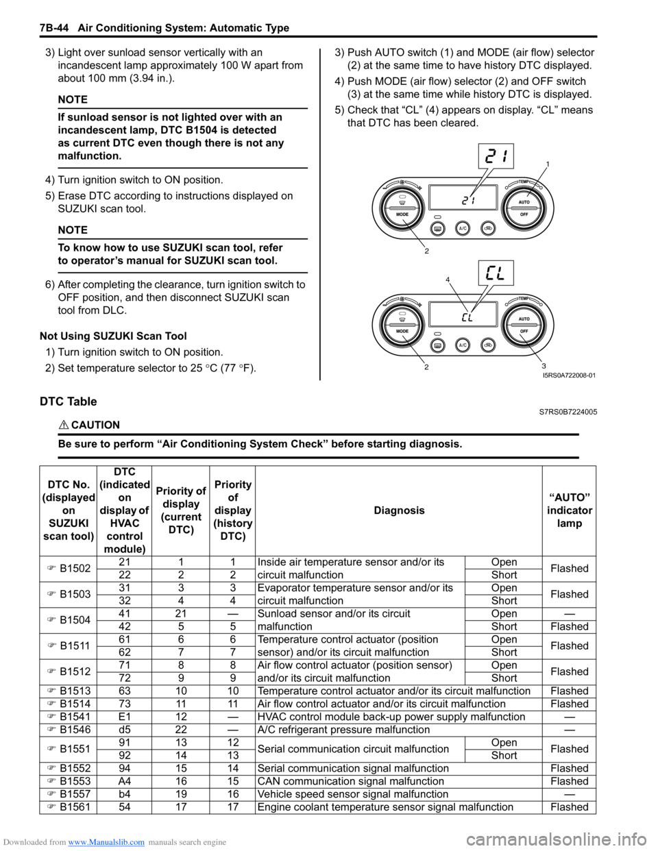
2) Set temperature selector to 25 °C (77 °F). 3) Push AUTO switch (1) and
MODE (air flow) selector
(2) at the same time to have history DTC displayed.
4) Push MODE (air flow) selector (2) and OFF switch (3) at the same time while history DTC is displayed.
5) Check that “CL” (4) appears on display. “CL” means that DTC has been cleared.
DTC TableS7RS0B7224005
CAUTION!
Be sure to perform “Air Conditioning Sy stem Check” before starting diagnosis.
1
2
3
2
4
I5RS0A722008-01
DTC No.
(displayed on
SUZUKI
scan tool) DTC
(indicated on
display of HVAC
control
module) Priority of
display
(current DTC) Priority
of
display
(history DTC) Diagnosis
“AUTO”
indicator lamp
) B1502 21 1 1 Inside air temperature sensor and/or its
circuit malfunction Open
Flashed
22 2 2 Short
) B1503 31 3 3 Evaporator temperature sensor and/or its
circuit malfunction Open
Flashed
32 4 4 Short
) B1504 41 21 — Sunload sensor and/or its circuit
malfunction Open —
42 5 5 Short Flashed
) B1511 61 6 6 Temperature control actuator (position
sensor) and/or its circuit malfunction Open
Flashed
62 7 7 Short
) B1512 71 8 8 Air flow control actuator (position sensor)
and/or its circuit malfunction Open
Flashed
72 9 9 Short
) B1513 63 10 10 Temperature control actuator and/or its circuit malfunction Flashed
) B1514 73 11 11 Air flow control actuator and/or its circuit malfunction Flashed
) B1541 E1 12 — HVAC control module back-up power supply malfunction —
) B1546 d5 22 — A/C refrigerant pressure malfunction —
) B1551 91 13 12
Serial communication circuit malfunction Open
Flashed
92 14 13 Short
) B1552 94 15 14 Serial communication signal malfunction Flashed
) B1553 A4 16 15 CAN communication signal malfunction Flashed
) B1557 b4 19 16 Vehicle speed sensor signal malfunction —
) B1561 54 17 17 Engine coolant temperature sensor signal malfunction Flashed
Page 1148 of 1496
Downloaded from www.Manualslib.com manuals search engine 8B-110 Air Bag System:
Installation
CAUTION!
Proper operation of forward-sensor requires
sensor be rigidly attached to vehicle
structure and that the arrow on sensor be
pointing toward the front of the vehicle.
1) Check that none of the following faulty conditions exists.
• Bend, deformity or rust of front panel.
• Foreign matter on mating surface of sensor.
2) Apply thread lock cement to mounting bolts thread. Install forward-sensor (1) on front panel and tighten
mounting bolt (2) to specified torque.
“A”: Thread lock cement 99000–32100 (Thread
Lock Cement 1305)
Tightening torque
Forward-sensor mounting bolt (a): 9 N·m (0.9
kgf-m, 6.5 lb-ft)
3) Connect forward-sensor connector by pushing connector till click is heard from it.
4) Connect negative cable at battery.
5) Enable air bag system referring to “Enabling Air Bag System”.
Forward-Sensor InspectionS7RS0B8206014
WARNING!
During service procedures, be very careful
when handling a sensor.
• Never strike or jar a sensor.
• A sensor and mounting bracket bolts must be carefully torqued to assure proper
operation. Under loose connection, it
could cause improper operation of the air
bag system.
CAUTION!
• Never disassemble forward-sensor.
• Sensor should be replaced when it was dropped from a height of 90 cm (3 ft) or
more.
• Check sensor for dents, cracks or deformation.
• Check sensor connector (sensor side and harness side) and sensor connector lock mechanism for
damage or crack.
• Check connector terminals for bend, corrosion or rust.
Side-Sensor Removal and InstallationS7RS0B8206015
WARNING!
During service procedures, be very careful
when handling a sensor.
• Never strike or jar a sensor.
• A sensor bolt must be carefully torqued to assure proper operation. Under loose
connection, it could cause improper
operation of the air bag system.
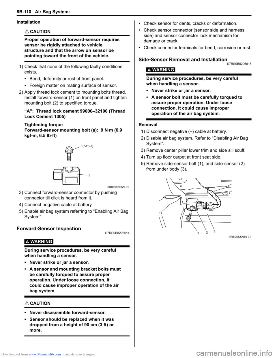
Removal
1) Disconnect negative (–) cable at battery.
2) Disable air bag system. Re fer to “Disabling Air Bag
System”.
3) Remove center pillar lowe r trim and side sill scuff.
4) Turn up floor carpet at front seat side.
5) Remove side-sensor bolt (1), and side-sensor (2) from under body (3).
2,"A",(a)
1
I5RH01820120-01
1 23I4RS0A820080-01
Page 1149 of 1496

Downloaded from www.Manualslib.com manuals search engine Air Bag System: 8B-111
6) Disconnect side-sensor connector sliding connector
outer (1) as shown.
Installation
CAUTION!
Proper operation of side-sensor requires
sensor be rigidly attached to specified
position.
1) Check that none of following faulty conditions exists.
• Bend, deformity or rust of under body.
• Foreign matter on mating surface of sensor.
2) Install side-sensor (1) on under body (2) and tighten side-sensor bolt (3) to specified torque.
Tightening torque
Side-sensor bolt (a): 9 N·m (0.9 kgf-m, 6.5 lb-ft) 3) Connect side-sensor connector pushing connector
inner (1) as shown.
4) Connect negative cable at battery.
5) Enable air bag system. Refer to “Enabling Air Bag System”.
Side-Sensor InspectionS7RS0B8206016
WARNING!
During service procedures, be very careful
when handling a sensor.
• Never strike or jar a sensor.
• A sensor and mounting bracket bolts must be carefully torqued to assure proper
operation. Under loose connection, it
could cause improper operation of the air
bag system.
CAUTION!
• Never disassemble side-sensor.
• Sensor should be replaced when it was dropped from a height of 90 cm (3 ft) or
more.
1
1
I4RS0A820109-01
1 2
3, (a)I4RS0A820081-01
1
1
I4RS0A820106-01
Page 1150 of 1496

Downloaded from www.Manualslib.com manuals search engine 8B-112 Air Bag System:
• Check sensor (1) for dents, crack, deformation.
• Check sensor connector (sensor side and harness side), lock mechanism or sensor lead wire for
damage, crack, scorching or melting.
• Check connector terminals for bent, corrosion or rust. If any faulty condition is found in above checks,
replace.
Passenger Air Bag (Inflator) Module Repair
Harness Installation
S7RS0B8206017
Replace passenger air bag (inflator) module repair
harness (4) according to the following procedure when
the harness (1) connect ed with passenger air bag
(inflator) module of the air bag harness included in
instrument panel harness (2) and passenger air bag
(inflator) module connector (3) is damaged. 1) Disable air bag system. Re
fer to “Disabling Air Bag
System”.
2) Disconnect “L32” connector from floor harness located near the glove box.
3) Cut off passenger air bag (inflator) module harness (1) included in instrument panel harness (2) as
shown, and then fasten it to instrument panel
harness with vinyl tape for avoiding interference with
other parts.
4) Install passenger air bag (inflator) module repair harness (1) to floor harness (2), instrument panel
harness (3) and passenger air bag (inflator) module.CAUTION!
To avoid interference with other parts, fasten
the repair harness to in strument wire harness
with a clamp or vinyl tape as shown in figure.
5) Connect each connector securely till click is heard.
5. Driver air bag (inflator) module 7. Floor harness
6. Passenger air bag (inflator) module 8. Vinyl tape
1I4RS0A820082-01
7
4
6
6
2
28
1
3
5
5
7I4RS0A820103-01
1
I4RS0A820083-01
1
2
3
I4RS0A820085-01
Page 1152 of 1496
Downloaded from www.Manualslib.com manuals search engine 8B-114 Air Bag System:
Deployment / Activation Outside of Vehicle
When you intend to return the vehicle to service, deploy
the air bag (inflator) module(s) or activate seat belt
pretensioner(s) outside of the vehicle.1) Turn ignition switch to LOCK position and remove key.
2) Wear safety glasses during this deployment / activation procedure.
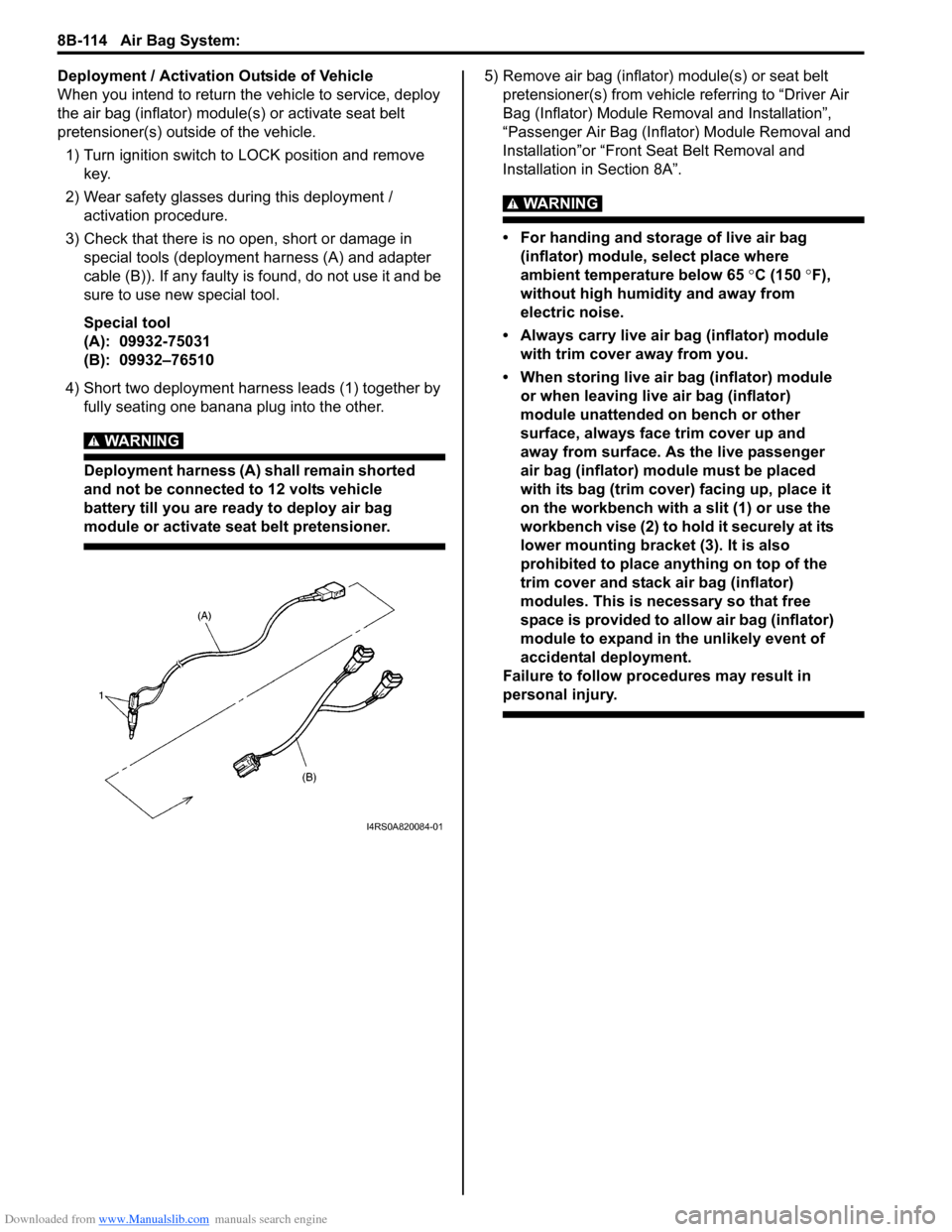
3) Check that there is no open, short or damage in special tools (deployment harness (A) and adapter
cable (B)). If any faulty is found, do not use it and be
sure to use new special tool.
Special tool
(A): 09932-75031
(B): 09932–76510
4) Short two deployment harness leads (1) together by fully seating one banana plug into the other.
WARNING!
Deployment harness (A) shall remain shorted
and not be connected to 12 volts vehicle
battery till you are ready to deploy air bag
module or activate seat belt pretensioner.
5) Remove air bag (inflator) module(s) or seat belt pretensioner(s) from vehicle referring to “Driver Air
Bag (Inflator) Module Re moval and Installation”,
“Passenger Air Bag (Inflator) Module Removal and
Installation”or “Front Seat Belt Removal and
Installation in Section 8A”.
WARNING!
• For handing and storage of live air bag (inflator) module, select place where
ambient temperature below 65 °C (150 °F),
without high humidity and away from
electric noise.
• Always carry live air bag (inflator) module with trim cover away from you.
• When storing live air bag (inflator) module or when leaving live air bag (inflator)
module unattended on bench or other
surface, always face trim cover up and
away from surface. As the live passenger
air bag (inflator) module must be placed
with its bag (trim cover) facing up, place it
on the workbench with a slit (1) or use the
workbench vise (2) to hold it securely at its
lower mounting bracket (3). It is also
prohibited to place anything on top of the
trim cover and stack air bag (inflator)
modules. This is necessary so that free
space is provided to allow air bag (inflator)
module to expand in the unlikely event of
accidental deployment.
Failure to follow procedures may result in
personal injury.
I4RS0A820084-01