Axle seal SUZUKI SWIFT 2008 2.G Service Workshop Manual
[x] Cancel search | Manufacturer: SUZUKI, Model Year: 2008, Model line: SWIFT, Model: SUZUKI SWIFT 2008 2.GPages: 1496, PDF Size: 34.44 MB
Page 40 of 1496
Downloaded from www.Manualslib.com manuals search engine 0B-10 Maintenance and Lubrication:
Steering System InspectionS7RS0B0206024
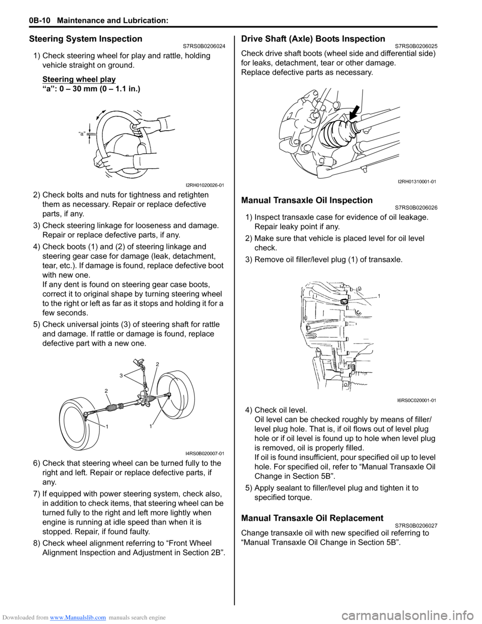
1) Check steering wheel for play and rattle, holding vehicle straight on ground.
Steering wheel play
“a”: 0 – 30 mm (0 – 1.1 in.)
2) Check bolts and nuts for tightness and retighten them as necessary. Repair or replace defective
parts, if any.
3) Check steering linkage for looseness and damage. Repair or replace defective parts, if any.
4) Check boots (1) and (2) of steering linkage and steering gear case for damage (leak, detachment,
tear, etc.). If damage is fo und, replace defective boot
with new one.
If any dent is found on steering gear case boots,
correct it to original shape by turning steering wheel
to the right or left as far as it stops and holding it for a
few seconds.
5) Check universal joints (3) of steering shaft for rattle and damage. If rattle or damage is found, replace
defective part with a new one.
6) Check that steering wheel can be turned fully to the
right and left. Repair or replace defective parts, if
any.
7) If equipped with power steering system, check also, in addition to check items, that steering wheel can be
turned fully to the right and left more lightly when
engine is running at idle speed than when it is
stopped. Repair, if found faulty.
8) Check wheel alignment referring to “Front Wheel Alignment Inspection and Adjustment in Section 2B”.
Drive Shaft (Axle) Boots InspectionS7RS0B0206025
Check drive shaft boots (wheel side and differential side)
for leaks, detachment, tear or other damage.
Replace defective parts as necessary.
Manual Transaxle Oil InspectionS7RS0B0206026
1) Inspect transaxle case for evidence of oil leakage. Repair leaky point if any.
2) Make sure that vehicle is placed level for oil level
check.
3) Remove oil filler/leve l plug (1) of transaxle.
4) Check oil level. Oil level can be checked roughly by means of filler/
level plug hole. That is, if oil flows out of level plug
hole or if oil level is found up to hole when level plug
is removed, oil is properly filled.
If oil is found insufficient, po ur specified oil up to level
hole. For specified oil, refe r to “Manual Transaxle Oil
Change in Section 5B”.
5) Apply sealant to filler/leve l plug and tighten it to
specified torque.
Manual Transaxle Oil ReplacementS7RS0B0206027
Change transaxle oil with new specified oil referring to
“Manual Transaxle Oil Change in Section 5B”.
I2RH01020026-01
2
3
2
1
1
I4RS0B020007-01
I2RH01310001-01
I6RS0C020001-01
Page 305 of 1496
Downloaded from www.Manualslib.com manuals search engine Engine Mechanical: 1D-20
15) Install A/C compressor to its bracket (if equipped) referring to “Compressor Assembly Removal and
Installation in Section 7B” or “Compressor Assembly
Removal and Installa tion in Section 7B”.
16) Adjust A/C compressor belt tension (if equipped) referring to “Compressor Drive Belt Inspection and
Adjustment in Section 7B” or “Compressor Drive Belt
Inspection and Adjustment in Section 7B”.
17) Check to ensure that a ll removed parts are back in
place.
Reinstall any necessary parts which have not been
reinstalled.
18) Refill cooling system with coolant referring to “Cooling System Flush and Refill in Section 1F”. 19) Refill engine with engine oil
referring to “Engine Oil
and Filter Change in Section 0B”.
20) Refill transaxle with transa xle oil referring to“Manual
Transaxle Oil Change in Section 5B” or “A/T Fluid
Change in Section 5A”.
21) Install battery and tray.
22) Connect positive and negative cable at battery.
23) Install engine hood and connect windshield washer hose.
24) Verify that there is no fu el leakage, coolant leakage,
oil leakage and exhaust gas leakage at each
connection.
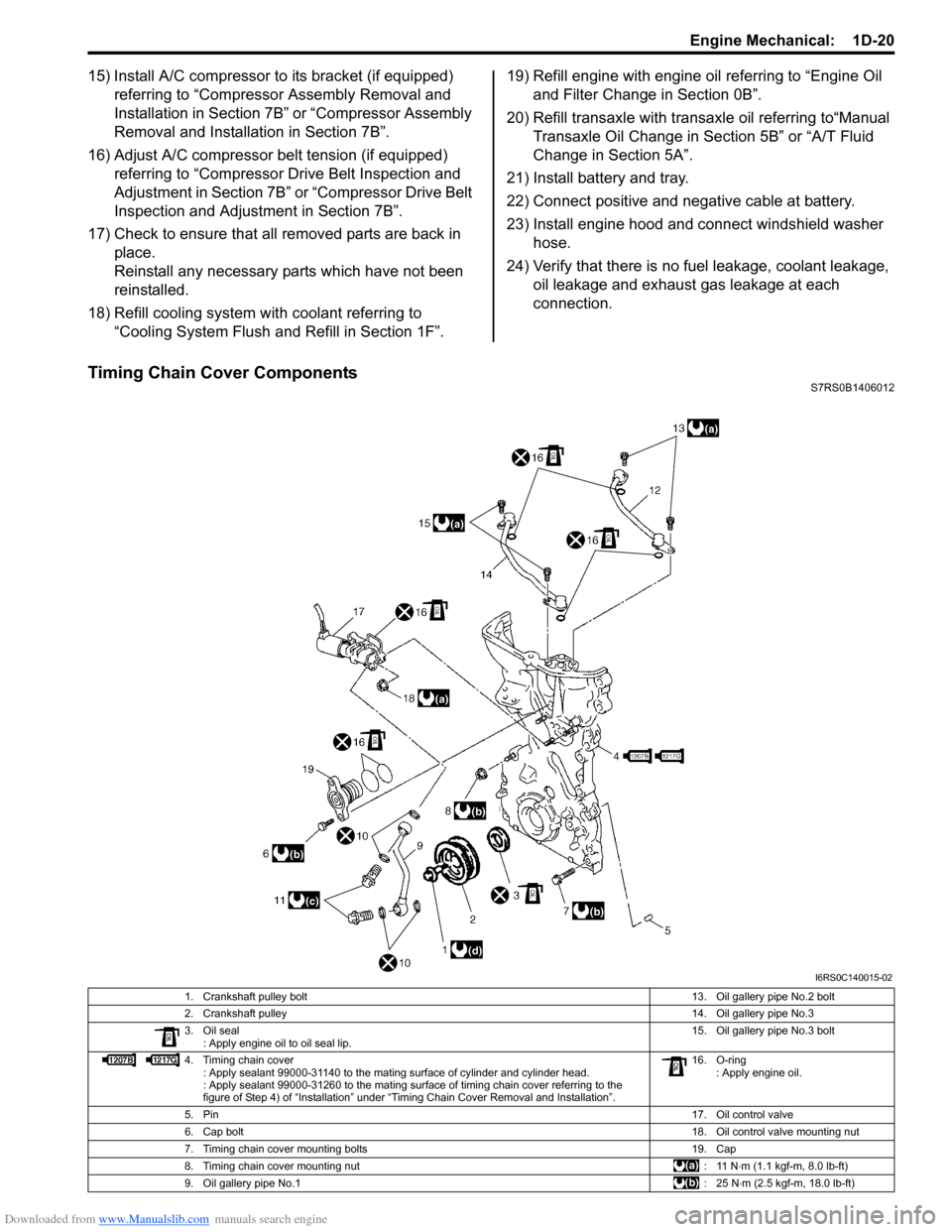
Timing Chain Cover ComponentsS7RS0B1406012
I6RS0C140015-02
1. Crankshaft pulley bolt 13. Oil gallery pipe No.2 bolt
2. Crankshaft pulley 14. Oil gallery pipe No.3
3. Oil seal : Apply engine oil to oil seal lip. 15. Oil gallery pipe No.3 bolt
4. Timing chain cover : Apply sealant 99000-31140 to the mating surface of cylinder and cylinder head.
: Apply sealant 99000-31260 to the mating surface of timing chain cover referring to the
figure of Step 4) of “Installation” under “Timing Chain Cover Removal and Installation”. 16. O-ring
: Apply engine oil.
5. Pin 17. Oil control valve
6. Cap bolt 18. Oil control valve mounting nut
7. Timing chain cover mounting bolts 19. Cap
8. Timing chain cover mounting nut : 11 N ⋅m (1.1 kgf-m, 8.0 lb-ft)
9. Oil gallery pipe No.1 :25 N⋅m (2.5 kgf-m, 18.0 lb-ft)
Page 355 of 1496
Downloaded from www.Manualslib.com manuals search engine Engine Lubrication System: 1E-3
6) Start engine and warm engine up to normal operating temperature.
NOTE
Be sure to shift transaxle gear shift lever in
“Neutral” (shift select lever in “P” range for
A/T vehicle), set parking brake and block
drive wheels.
7) After warming up, raise engine speed to 4,000 r/min. and measure oil pressure.
Oil pressure specification
More than 270 kPa (2.7 kg/cm2, 39.8 psi) at 4,000
r/min. (rpm)
8) After checking oil pressure, stop engine and remove oil pressure gauge and attachment.
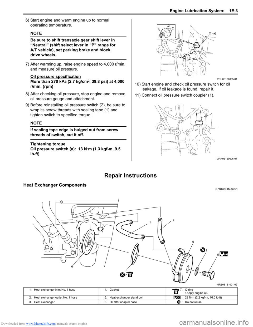
9) Before reinstalling oil pressure switch (2), be sure to
wrap its screw threads with sealing tape (1) and
tighten switch to specified torque.
NOTE
If sealing tape edge is bulged out from screw
threads of switch, cut it off.
Tightening torque
Oil pressure switch (a): 13 N·m (1.3 kgf-m, 9.5
lb-ft) 10) Start engine and check oil pressure switch for oil
leakage. If oil leakage is found, repair it.
11) Connect oil pressure switch coupler (1).
Repair Instructions
Heat Exchanger ComponentsS7RS0B1506001
I2RH0B150005-01
I2RH0B150006-01
3
4
5
7
6
(a)
2
1
I6RS0B151001-02
1. Heat exchanger inlet No. 1 hose 4. Gasket7. O-ring
: Apply engine oil.
2. Heat exchanger outlet No. 1 hose 5. Heat exchanger stand bolt : 22 N⋅m (2.2 kgf-m, 16.0 lb-ft)
3. Heat exchanger 6. Oil filter adapter case : Do not reuse.
Page 357 of 1496
Downloaded from www.Manualslib.com manuals search engine Engine Lubrication System: 1E-5
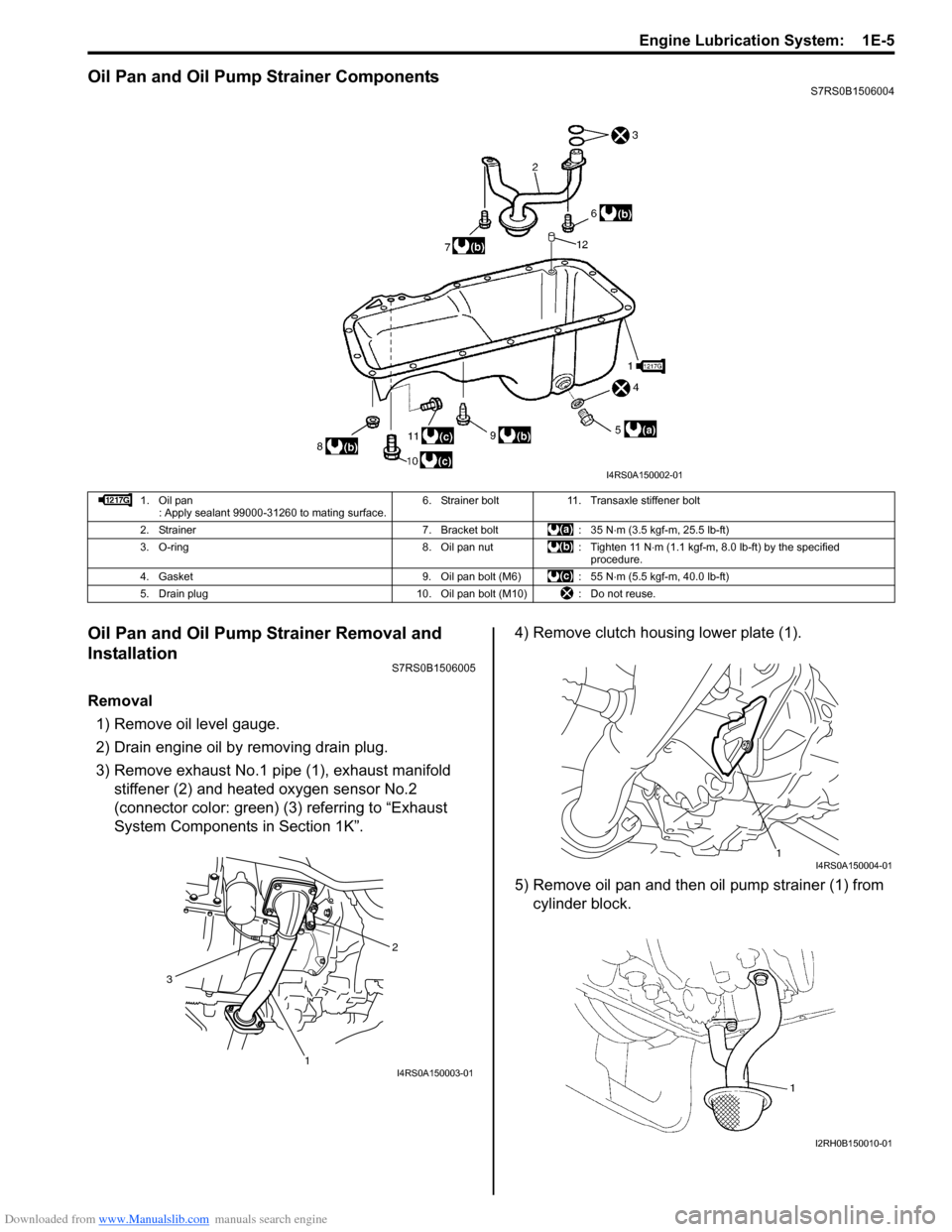
Oil Pan and Oil Pump Strainer ComponentsS7RS0B1506004
Oil Pan and Oil Pump Strainer Removal and
Installation
S7RS0B1506005
Removal1) Remove oil level gauge.
2) Drain engine oil by removing drain plug.
3) Remove exhaust No.1 pipe (1), exhaust manifold stiffener (2) and heated oxygen sensor No.2
(connector color: green) (3) referring to “Exhaust
System Components in Section 1K”. 4) Remove clutch housing lower plate (1).
5) Remove oil pan and then oil pump strainer (1) from
cylinder block.
I4RS0A150002-01
1. Oil pan : Apply sealant 99000-31260 to mating surface. 6. Strainer bolt 11. Transaxle stiffener bolt
2. Strainer 7. Bracket bolt : 35 N ⋅m (3.5 kgf-m, 25.5 lb-ft)
3. O-ring 8. Oil pan nut : Tighten 11 N ⋅m (1.1 kgf-m, 8.0 lb-ft) by the specified
procedure.
4. Gasket 9. Oil pan bolt (M6) : 55 N ⋅m (5.5 kgf-m, 40.0 lb-ft)
5. Drain plug 10. Oil pan bolt (M10) : Do not reuse.
2
1
3
I4RS0A150003-01
1I4RS0A150004-01
I2RH0B150010-01
Page 359 of 1496
Downloaded from www.Manualslib.com manuals search engine Engine Lubrication System: 1E-7
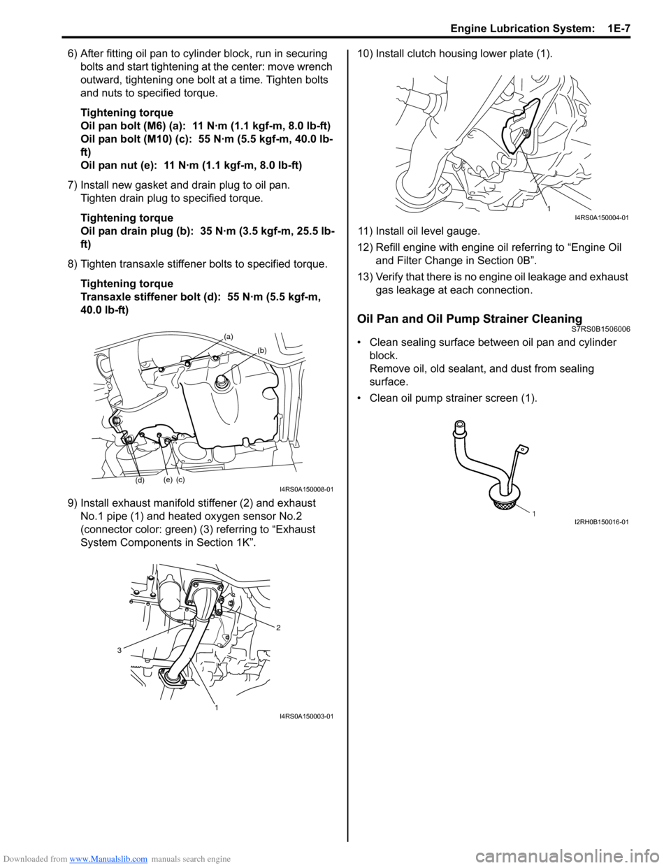
6) After fitting oil pan to cylinder block, run in securing bolts and start tightening at the center: move wrench
outward, tightening one bolt at a time. Tighten bolts
and nuts to specified torque.
Tightening torque
Oil pan bolt (M6) (a): 11 N·m (1.1 kgf-m, 8.0 lb-ft)
Oil pan bolt (M10) (c): 55 N·m (5.5 kgf-m, 40.0 lb-
ft)
Oil pan nut (e): 11 N·m (1.1 kgf-m, 8.0 lb-ft)
7) Install new gasket and drain plug to oil pan. Tighten drain plug to specified torque.
Tightening torque
Oil pan drain plug (b): 35 N·m (3.5 kgf-m, 25.5 lb-
ft)
8) Tighten transaxle stiffener bolts to specified torque. Tightening torque
Transaxle stiffener bolt (d): 55 N·m (5.5 kgf-m,
40.0 lb-ft)
9) Install exhaust manifold stiffener (2) and exhaust No.1 pipe (1) and heated oxygen sensor No.2
(connector color: green) (3) referring to “Exhaust
System Components in Section 1K”. 10) Install clutch housing lower plate (1).
11) Install oil level gauge.
12) Refill engine with engine oil referring to “Engine Oil
and Filter Change in Section 0B”.
13) Verify that there is no en gine oil leakage and exhaust
gas leakage at each connection.
Oil Pan and Oil Pump Strainer CleaningS7RS0B1506006
• Clean sealing surface between oil pan and cylinder block.
Remove oil, old sealant, and dust from sealing
surface.
• Clean oil pump strainer screen (1).(a)
(b)
(c)(e)
(d)I4RS0A150008-01
2
1
3
I4RS0A150003-01
1I4RS0A150004-01
I2RH0B150016-01
Page 363 of 1496
Downloaded from www.Manualslib.com manuals search engine Engine Lubrication System: 1E-11
Specifications
Tightening Torque SpecificationsS7RS0B1507001
NOTE
The specified tightening torque is also described in the following.
“Heat Exchanger Components”
“Oil Pan and Oil Pump Strainer Components”
“Oil Pump Components”
Reference:
For the tightening torque of fastener not specified in this section, refer to “Fasteners Information in Section 0A”.
Special Tools and Equipment
Recommended Service MaterialS7RS0B1508001
NOTE
Required service material is also described in the following.
“Heat Exchanger Components”
“Oil Pan and Oil Pump Strainer Components”
“Oil Pump Components”
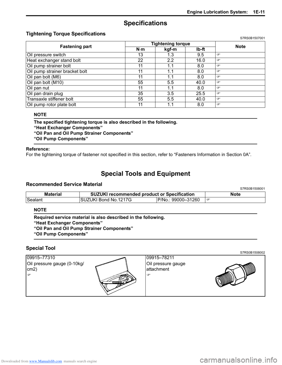
Special ToolS7RS0B1508002
Fastening part Tightening torque
Note
N ⋅mkgf-mlb-ft
Oil pressure switch 13 1.3 9.5 �)
Heat exchanger stand bolt 22 2.2 16.0 �)
Oil pump strainer bolt 11 1.1 8.0 �)
Oil pump strainer bracket bolt 11 1.1 8.0 �)
Oil pan bolt (M6) 11 1.1 8.0 �)
Oil pan bolt (M10) 55 5.5 40.0 �)
Oil pan nut 11 1.1 8.0 �)
Oil pan drain plug 35 3.5 25.5 �)
Transaxle stiffener bolt 55 5.5 40.0 �)
Oil pump rotor plate bolt 11 1.1 8.0 �)
MaterialSUZUKI recommended product or Specification Note
Sealant SUZUKI Bond No.1217G P/No.: 99000–31260�)
09915–77310 09915–78211
Oil pressure gauge (0-10kg/
cm2) Oil pressure gauge
attachment
�)�)
Page 455 of 1496
Downloaded from www.Manualslib.com manuals search engine Rear Suspension: 2C-1
Suspension
Rear Suspension
General Description
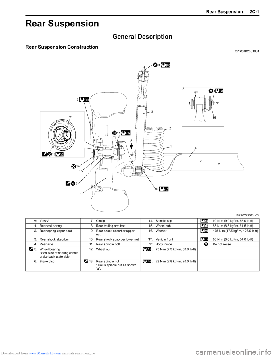
Rear Suspension ConstructionS7RS0B2301001
I6RS0C230001-03
A: View A7. Circlip 14. Spindle cap : 90 N⋅m (9.0 kgf-m, 65.0 lb-ft)
1. Rear coil spring 8. Rear trailing arm bolt 15. Wheel hub : 85 N⋅m (8.5 kgf-m, 61.5 lb-ft)
2. Rear spring upper seat 9. Rear shock absorber upper
nut 16. Washer
: 175 N⋅m (17.5 kgf-m, 126.5 lb-ft)
3. Rear shock absorber 10. Rear shock absorber lower nut “F”: Vehicle front : 88 N⋅m (8.8 kgf-m, 64.0 lb-ft)
4. Rear axle 11. Rear spindle bolt “I”: Body inside : Do not reuse.
5. Wheel bearing : Seal side of bearing comes
brake back plate side. 12. Wheel nut
: 73 N⋅m (7.3 kgf-m, 53.0 lb-ft)
6. Brake disc 13. Rear spindle nut
: Caulk spindle nut as shown
“a”. :28 N
⋅m (2.8 kgf-m, 20.0 lb-ft)
Page 457 of 1496
Downloaded from www.Manualslib.com manuals search engine Rear Suspension: 2C-3
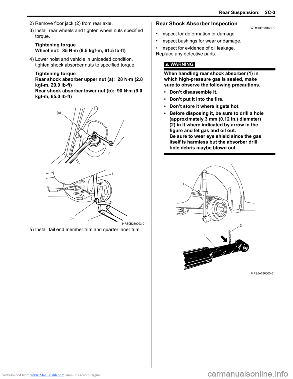
2) Remove floor jack (2) from rear axle.
3) Install rear wheels and tighten wheel nuts specified torque.
Tightening torque
Wheel nut: 85 N·m (8.5 kgf-m, 61.5 lb-ft)
4) Lower hoist and vehicle in unloaded condition, tighten shock absorber nuts to specified torque.
Tightening torque
Rear shock absorber upper nut (a): 28 N·m (2.8
kgf-m, 20.0 lb-ft)
Rear shock absorber lower nut (b): 90 N·m (9.0
kgf-m, 65.0 lb-ft)
5) Install tail end member trim and quarter inner trim.Rear Shock Absorber InspectionS7RS0B2306002
• Inspect for deformation or damage.
• Inspect bushings for wear or damage.
• Inspect for evidence of oil leakage.
Replace any defective parts.
WARNING!
When handling rear shock absorber (1) in
which high-pressure gas is sealed, make
sure to observe the following precautions.
• Don’t disassemble it.
• Don’t put it into the fire.
• Don’t store it where it gets hot.
• Before disposing it, be sure to drill a hole (approximately 3 mm (0.12 in.) diameter)
(2) in it where indicated by arrow in the
figure and let gas and oil out.
Be sure to wear eye shield since the gas
itself is harmless but the absorber drill
hole debris maybe blown out.
(a)
1
(b) 2
I4RS0B230003-01
I4RS0A230005-01
Page 468 of 1496
Downloaded from www.Manualslib.com manuals search engine 2D-1 Wheels and Tires:
Suspension
Wheels and Tires
Precautions
Precaution for Emergency Flat Tire Repair KitS7RS0B2400001
WARNING!
Flat tire repair sealant including in kit is
harmful. Be sure to observe the following.
Otherwise, your health may be ruined.
• If swallowed, get medical attention immediately.
• Keep out of reach of children.
• Select place where there is good ventilation for this work.
• If it enters eye or contacts skin, wash thoroughly with water. If anything
abnormal still rema ins, get medical
attention immediately.
• Do not discard tire containing sealant as it is. Make sure to remove sealant from tire,
referring to “Tire Repair for Emergency
Repaired-Tire with Sealant”.
• Dispose of sealant as waste oil.
CAUTION!
• When tire repaired with Emergency Flat Tire Repair Kit is brought in, remove flat
tire repair sealant from tire and repair flat
tire referring to “Tire Repair for Emergency
Repaired-Tire with Sealant”.
• Sealant expiration date is printed on bottle label. if it expires, sealant should be
replaced with a new one to ensure
emergency flat tire repair.
General Description
Tires DescriptionS7RS0B2401001
The tire is of tubeless type. The tire is designed to
operate satisfactorily with loads up to the full rated load
capacity when inflated to the recommended inflation
pressures.
Correct tire pressures and driving habits have an
important influence on tire life. Heavy cornering,
excessively rapid acceleration, and unnecessary sharp
braking increase tire wear.
Tire Placard
The “Tire Placard” is located on the left or right door lock
pillar and should be referred to tire information.
The placard lists the maximum load, tire size and cold
tire pressure where applicable.
NOTE
Whether rim size and/or maximum load are
listed or not depends on regulations of each
country.
Inflation of Tires
The pressure recommended for any model is carefully
calculated to give a satisfacto ry ride, stability, steering,
tread wear, tire life and resistance to bruises.
Tire pressure, with tires cold, (after vehicle has set for 3
hours or more, or driven less than one mile) should be
checked monthly or before any extended trip. Set to the
specifications on the “Tire Placard” located on the left
door lock pillar.
It is normal for tire pressure to increase when the tires
become hot during driving.
Do not bleed or reduce tire pressure after driving.
Bleeding reduces the “Cold Inflation Pressure”.
Higher than recommended pressure can cause:
• Hard ride
• Tire bruising or carcass damage
• Rapid tread wear at center of tire
Unequal pressure on same axle can cause:
• Uneven braking
• Steering lead
• Reduced handling
• Swerve on acceleration
Page 482 of 1496
Downloaded from www.Manualslib.com manuals search engine 3A-4 Drive Shaft / Axle:
Front Drive Shaft Assembly On-Vehicle
Inspection
S7RS0B3106002
• Check boots for breakage or deterioration.
• Check wheel side joint for rattle or smooth rotation.
• Check differential side (or center shaft side) joint for smooth rotation.
If any abnormality is found, replace.
Front Drive Shaft Assembly Removal and
Installation
S7RS0B3106003
Removal
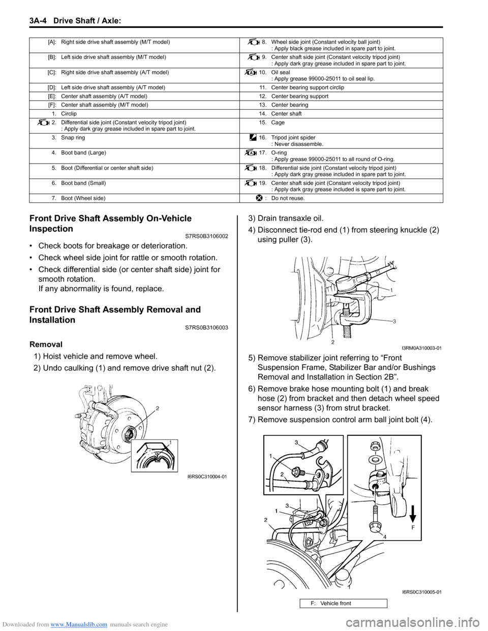
1) Hoist vehicle and remove wheel.
2) Undo caulking (1) and remove drive shaft nut (2). 3) Drain transaxle oil.
4) Disconnect tie-rod end (1) from steering knuckle (2)
using puller (3).
5) Remove stabilizer join t referring to “Front
Suspension Frame, Stabiliz er Bar and/or Bushings
Removal and Installati on in Section 2B”.
6) Remove brake hose mounting bolt (1) and break hose (2) from bracket and then detach wheel speed
sensor harness (3) from strut bracket.
7) Remove suspension contro l arm ball joint bolt (4).
[A]: Right side drive shaft assembly (M/T model) 8. Wheel side joint (Constant velocity ball joint)
: Apply black grease included in spare part to joint.
[B]: Left side drive shaft assembly (M/T model) 9. Center shaft side joint (Constant velocity tripod joint)
: Apply dark gray grease included in spare part to joint.
[C]: Right side drive shaft assembly (A/T model) 10. Oil seal
: Apply grease 99000-25011 to oil seal lip.
[D]: Left side drive shaft assembly (A/T model) 11. Center bearing support circlip
[E]: Center shaft assembly (A/T model) 12. Center bearing support
[F]: Center shaft assembly (M/T model) 13. Center bearing
1. Circlip 14. Center shaft
2. Differential side joint (Constant velocity tripod joint) : Apply dark gray grease included in spare part to joint. 15. Cage
3. Snap ring 16. Tripod joint spider
: Never disassemble.
4. Boot band (Large) 17. O-ring
: Apply grease 99000-25011 to all round of O-ring.
5. Boot (Differential or center shaft side) 18. Differential side joint (Constant velocity tripod joint)
: Apply dark gray grease included in spare part to joint.
6. Boot band (Small) 19. Center shaft side joint (Constant velocity tripod joint)
: Apply dark gray grease included is spare part to joint.
7. Boot (Wheel side) : Do not reuse.
I6RS0C310004-01
F: Vehicle front
I3RM0A310003-01
I6RS0C310005-01