door handle SUZUKI SWIFT 2008 2.G Service Workshop Manual
[x] Cancel search | Manufacturer: SUZUKI, Model Year: 2008, Model line: SWIFT, Model: SUZUKI SWIFT 2008 2.GPages: 1496, PDF Size: 34.44 MB
Page 41 of 1496
Downloaded from www.Manualslib.com manuals search engine Maintenance and Lubrication: 0B-11
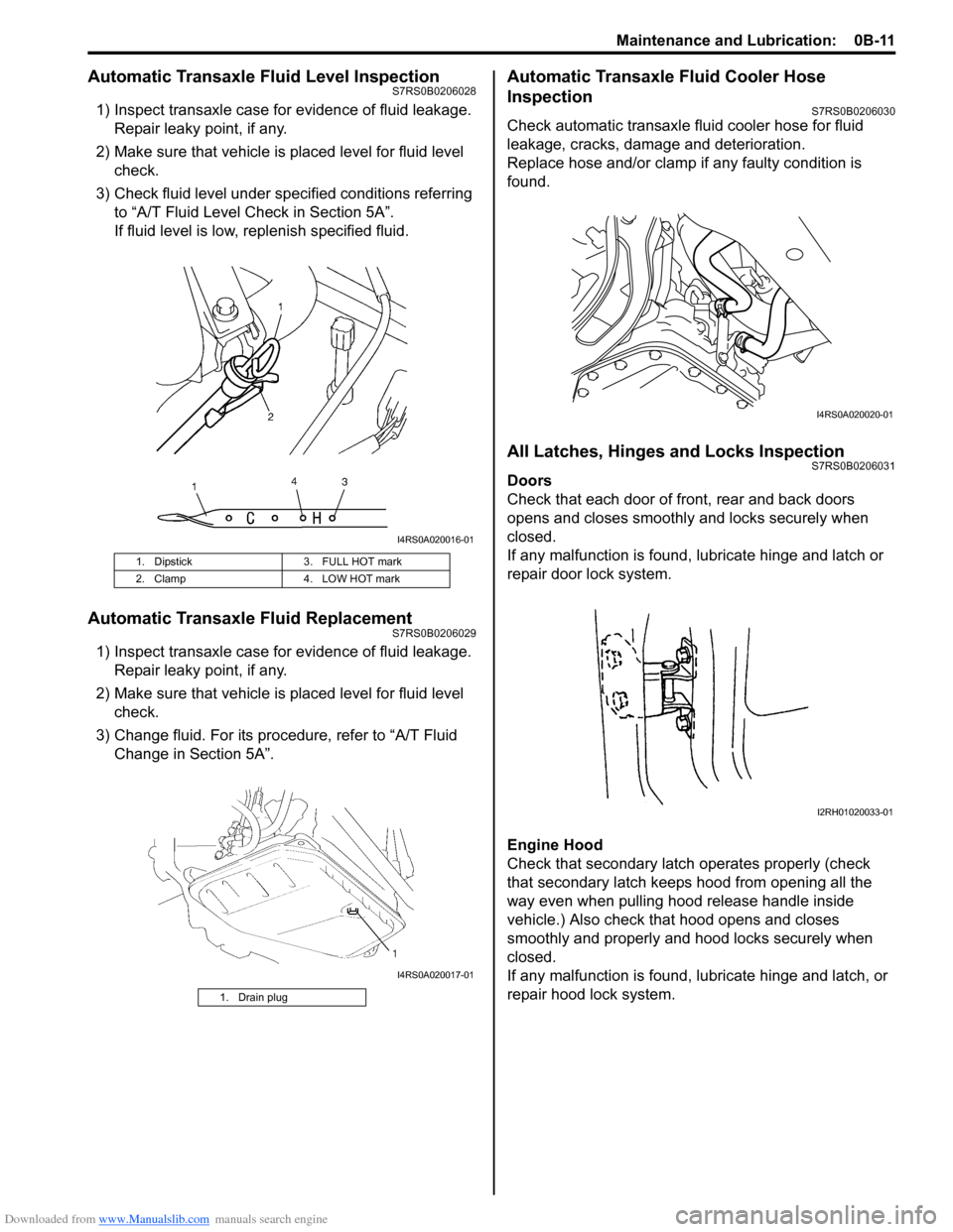
Automatic Transaxle Fluid Level InspectionS7RS0B0206028
1) Inspect transaxle case for evidence of fluid leakage.Repair leaky point, if any.
2) Make sure that vehicle is placed level for fluid level check.
3) Check fluid level under spec ified conditions referring
to “A/T Fluid Level Check in Section 5A”.
If fluid level is low, replenish specified fluid.
Automatic Transaxle Fluid ReplacementS7RS0B0206029
1) Inspect transaxle case for evidence of fluid leakage. Repair leaky point, if any.
2) Make sure that vehicle is placed level for fluid level check.
3) Change fluid. For its procedure, refer to “A/T Fluid Change in Section 5A”.
Automatic Transaxle Fluid Cooler Hose
Inspection
S7RS0B0206030
Check automatic transaxle fluid cooler hose for fluid
leakage, cracks, damage and deterioration.
Replace hose and/or clamp if any faulty condition is
found.
All Latches, Hinges and Locks InspectionS7RS0B0206031
Doors
Check that each door of front, rear and back doors
opens and closes smoothly and locks securely when
closed.
If any malfunction is found, lubricate hinge and latch or
repair door lock system.
Engine Hood
Check that secondary latch operates properly (check
that secondary latch keeps hood from opening all the
way even when pulling hood release handle inside
vehicle.) Also check that hood opens and closes
smoothly and properly and hood locks securely when
closed.
If any malfunction is found, l ubricate hinge and latch, or
repair hood lock system.
1. Dipstick 3. FULL HOT mark
2. Clamp 4. LOW HOT mark
1. Drain plug
I4RS0A020016-01
I4RS0A020017-01
I4RS0A020020-01
I2RH01020033-01
Page 1351 of 1496
Downloaded from www.Manualslib.com manuals search engine Security and Locks: 9F-5
Keyless Entry System Operation InspectionS7RS0B9604004
NOTE
When performing the this inspection, make
sure to have any of the door once opened/
closed after the ignition key has been
removed from the ignition key cylinder.
1) Confirm that power door lock system operates normally, refer to “Power Door Lock System
Operation Inspection”.
2) All doors are closed and unlocked.
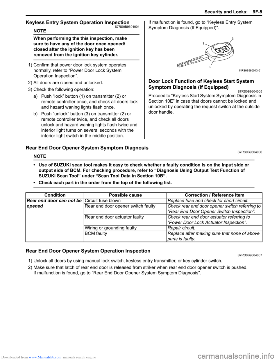
3) Check the following operation: a) Push “lock” button (1 ) on transmitter (2) or
remote controller once, and check all doors lock
and hazard waning lights flash once.
b) Push “unlock” button (3) on transmitter (2) or remote controller twice, and check all doors
unlock and hazard waning lights flash twice and
interior light turns on several seconds with the
interior light switch in the middle position. If malfunction is found, go to “Keyless Entry System
Symptom Diagnosis (If Equipped)”.
Door Lock Function of Keyless Start System
Symptom Diagnosis (If Equipped)
S7RS0B9604005
Proceed to “Keyless Start System Symptom Diagnosis in
Section 10E” in case that doors cannot be locked and
unlocked by operating the request switch at the outside
door handle.
Rear End Door Opener System Symptom DiagnosisS7RS0B9604006
NOTE
• Use of SUZUKI scan tool makes it easy to check wh
ether a faulty condition is on the input side or
output side of BCM. For checking procedure, re fer to “Diagnosis Using Output Test Function of
SUZUKI Scan Tool” under “Scan Tool Data in Section 10B”.
• Check each part in the order from the top of the following list.
Rear End Door Opener System Operation InspectionS7RS0B9604007
1) Unlock all doors by using manu al lock switch, keyless entry transmitter, or key cylinder switch.
2) Make sure that latch of rear end door is released from striker when rear end door opener switch is pushed. If malfunction is found, go to “Rear End Door Opener System Symptom Diagnosis”.
1
3
2I4RS0B960013-01
ConditionPossible cause Correction / Reference Item
Rear end door can not be
opened Circuit fuse blown
Replace fuse and check for short circuit.
Rear end door opener switch faulty Check rear end door opener switch referring to
“Rear End Door Opener Switch Inspection”.
Rear end door actuator faulty Check rear end door actuator referring to
“Power Door Lock Actuator Inspection”.
Wiring or grounding faulty Repair circuit.
BCM faulty Replace after making sure that none of above
parts is faulty.
Page 1352 of 1496
Downloaded from www.Manualslib.com manuals search engine 9F-6 Security and Locks:
Repair Instructions
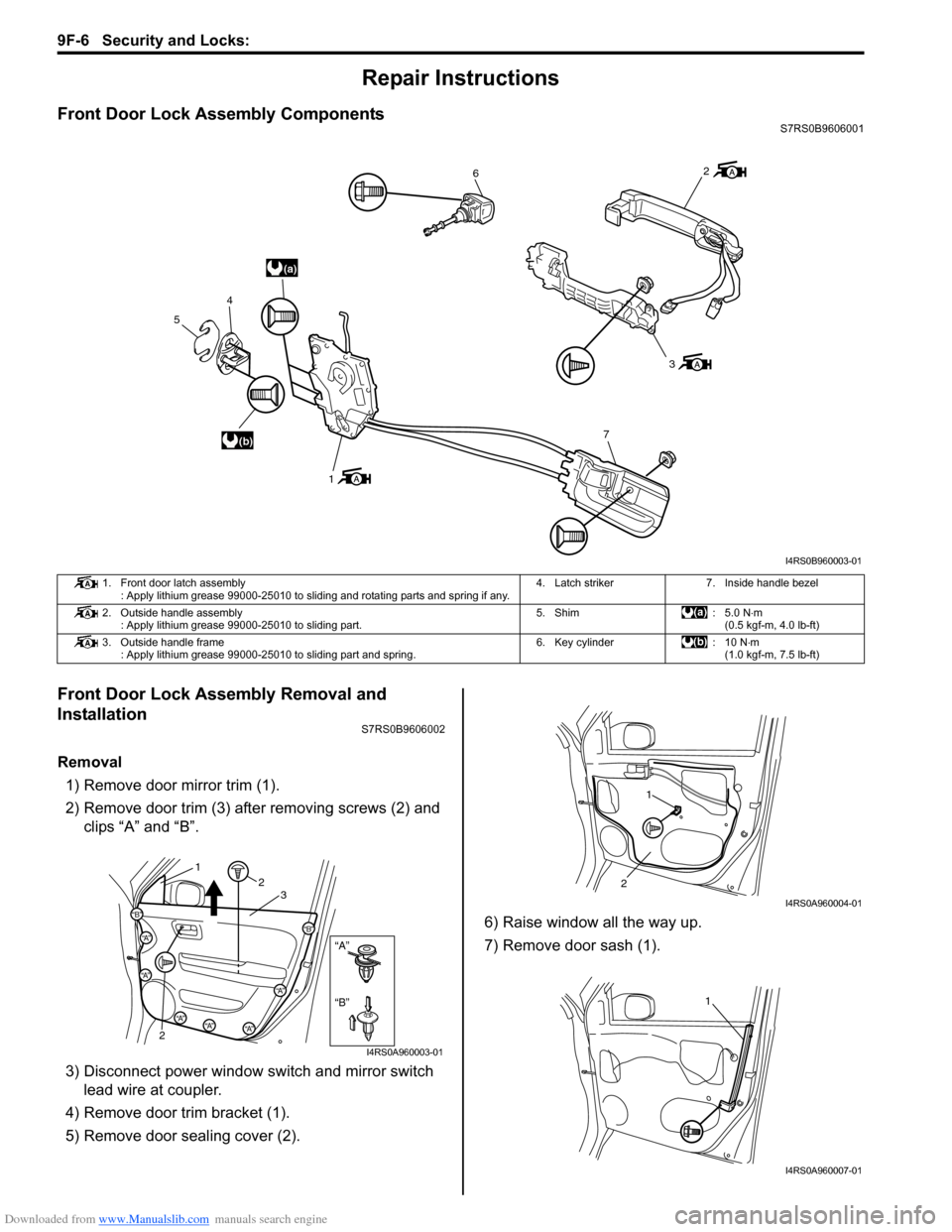
Front Door Lock Assembly ComponentsS7RS0B9606001
Front Door Lock Assembly Removal and
Installation
S7RS0B9606002
Removal1) Remove door mirror trim (1).
2) Remove door trim (3) after removing screws (2) and clips “A” and “B”.
3) Disconnect power window s witch and mirror switch
lead wire at coupler.
4) Remove door trim bracket (1).
5) Remove door sealing cover (2). 6) Raise window all the way up.
7) Remove door sash (1).
(a)
(b)
6
3
7
1
4
5
2
I4RS0B960003-01
1. Front door latch assembly : Apply lithium grease 99000-25010 to sliding and rotating parts and spring if any. 4. Latch striker 7. Inside handle bezel
2. Outside handle assembly : Apply lithium grease 99000-25010 to sliding part. 5. Shim : 5.0 N
⋅m
(0.5 kgf-m, 4.0 lb-ft)
3. Outside handle frame : Apply lithium grease 99000-25010 to sliding part and spring. 6. Key cylinder : 10 N⋅m
(1.0 kgf-m, 7.5 lb-ft)
“B”
“A”
“B”
“A”
“B”“A”
“A”
“A”“A”“A”
12
2 3
I4RS0A960003-01
1
2
I4RS0A960004-01
1
I4RS0A960007-01
Page 1353 of 1496
Downloaded from www.Manualslib.com manuals search engine Security and Locks: 9F-7
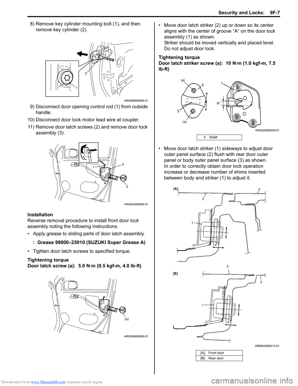
8) Remove key cylinder mounting bolt (1), and then remove key cylinder (2).
9) Disconnect door opening control rod (1) from outside handle.
10) Disconnect door lock motor lead wire at coupler. 11) Remove door latch screws (2) and remove door lock assembly (3).
Installation
Reverse removal procedure to install front door lock
assembly noting the following instructions.
• Apply grease to sliding parts of door latch assembly.
: Grease 99000–25010 (SUZUKI Super Grease A)
• Tighten door latch screws to specified torque.
Tightening torque
Door latch screw (a): 5.0 N·m (0.5 kgf-m, 4.0 lb-ft) • Move door latch striker (2) up or down so its center
aligns with the center of groove “A” on the door lock
assembly (1) as shown.
Striker should be moved vertically and placed level.
Do not adjust door lock.
Tightening torque
Door latch striker screw (a): 10 N·m (1.0 kgf-m, 7.5
lb-ft)
• Move door latch striker (1) sideways to adjust door outer panel surface (2) flush with rear door outer
panel or body outer panel surface (3) as shown.
In order to correctly obtain door lock operation
increase or decrease number of shims inserted
between body and striker (1) to adjust it.
1 2
I4RS0B960005-01
1
2
3
I4RS0A960006-01
(a)
I4RS0A960008-01
3. Shaft
[A]: Front door
[B]: Rear door
I4RS0A960029-01
I3RM0A960013-01
Page 1356 of 1496
Downloaded from www.Manualslib.com manuals search engine 9F-10 Security and Locks:
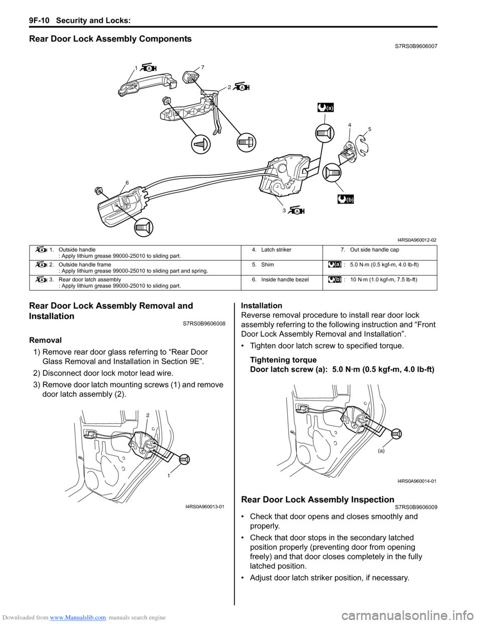
Rear Door Lock Assembly ComponentsS7RS0B9606007
Rear Door Lock Assembly Removal and
Installation
S7RS0B9606008
Removal1) Remove rear door glass referring to “Rear Door Glass Removal and Installation in Section 9E”.
2) Disconnect door lock motor lead wire.
3) Remove door latch mounting screws (1) and remove door latch assembly (2). Installation
Reverse removal procedure to install rear door lock
assembly referring to the following instruction and “Front
Door Lock Assembly Re
moval and Installation”.
• Tighten door latch screw to specified torque.
Tightening torque
Door latch screw (a): 5.0 N·m (0.5 kgf-m, 4.0 lb-ft)
Rear Door Lock Assembly InspectionS7RS0B9606009
• Check that door opens and closes smoothly and properly.
• Check that door stops in the secondary latched position properly (preventing door from opening
freely) and that door closes completely in the fully
latched position.
• Adjust door latch strike r position, if necessary.
(a)
(b)
1
7
2
6
3 4
5
I4RS0A960012-02
1. Outside handle
: Apply lithium grease 99000-25010 to sliding part. 4. Latch striker 7. Out side handle cap
2. Outside handle frame : Apply lithium grease 99000-25010 to sliding part and spring. 5. Shim : 5.0 N
⋅m (0.5 kgf-m, 4.0 lb-ft)
3. Rear door latch assembly : Apply lithium grease 99000-25010 to sliding part. 6. Inside handle bezel : 10 N
⋅m (1.0 kgf-m, 7.5 lb-ft)
1
2
I4RS0A960013-01
(a)
I4RS0A960014-01
Page 1357 of 1496
Downloaded from www.Manualslib.com manuals search engine Security and Locks: 9F-11
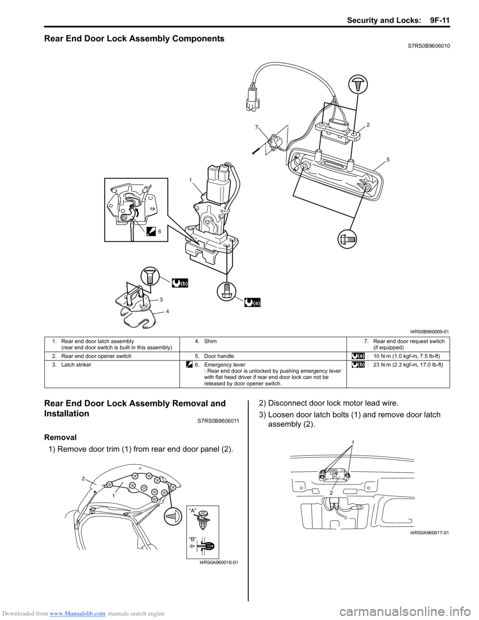
Rear End Door Lock Assembly ComponentsS7RS0B9606010
Rear End Door Lock Assembly Removal and
Installation
S7RS0B9606011
Removal1) Remove door trim (1) from rear end door panel (2). 2) Disconnect door lock motor lead wire.
3) Loosen door latch bolts (1) and remove door latch
assembly (2).
1
7
3 4 5
2
(a)
(b)
6
I4RS0B960009-01
1. Rear end door latch assembly
(rear end door switch is built in this assembly) 4. Shim 7. Rear end door request switch
(if equipped)
2. Rear end door opener switch 5. Door handle : 10 N⋅ m (1.0 kgf-m, 7.5 lb-ft)
3. Latch striker 6. Emergency lever : Rear end door is unlocked by pushing emergency lever
with flat head driver if rear end door lock can not be
released by door opener switch. :23 N
⋅m (2.3 kgf-m, 17.0 lb-ft)
“A”
“B”
“B”
“A”“B”“A”“A”“A”
“A”“A”“A”
“A”
2
1
I4RS0A960016-01
1
2
I4RS0A960017-01
Page 1376 of 1496
Downloaded from www.Manualslib.com manuals search engine 9J-7 Hood / Fenders / Doors:
WARNING!
Handling of Rear End Door Balancer
(Damper)
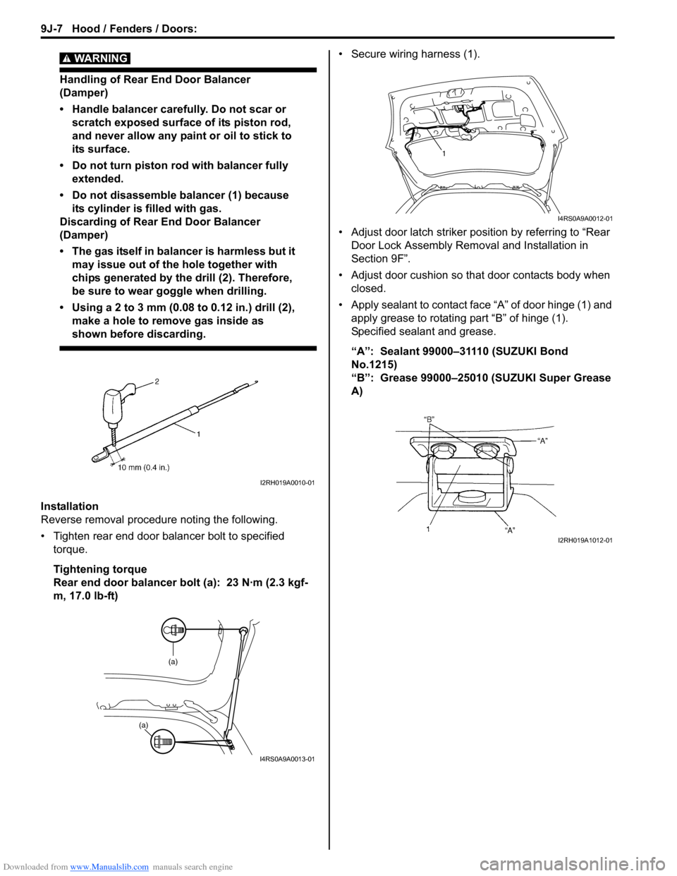
• Handle balancer carefully. Do not scar or scratch exposed surface of its piston rod,
and never allow any paint or oil to stick to
its surface.
• Do not turn piston rod with balancer fully extended.
• Do not disassemble balancer (1) because its cylinder is filled with gas.
Discarding of Rear End Door Balancer
(Damper)
• The gas itself in balancer is harmless but it may issue out of the hole together with
chips generated by th e drill (2). Therefore,
be sure to wear goggle when drilling.
• Using a 2 to 3 mm (0.08 to 0.12 in.) drill (2),
make a hole to remove gas inside as
shown before discarding.
Installation
Reverse removal procedure noting the following.
• Tighten rear end door balancer bolt to specified torque.
Tightening torque
Rear end door balancer bolt (a): 23 N·m (2.3 kgf-
m, 17.0 lb-ft) • Secure wiring harness (1).
• Adjust door latch striker position by referring to “Rear
Door Lock Assembly Removal and Installation in
Section 9F”.
• Adjust door cushion so that door contacts body when closed.
• Apply sealant to contact face “A” of door hinge (1) and apply grease to rotating part “B” of hinge (1).
Specified sealant and grease.
“A”: Sealant 99000–31110 (SUZUKI Bond
No.1215)
“B”: Grease 99000–25010 (SUZUKI Super Grease
A)
I2RH019A0010-01
(a)
(a)
I4RS0A9A0013-01
1
I4RS0A9A0012-01
I2RH019A1012-01
Page 1404 of 1496
Downloaded from www.Manualslib.com manuals search engine 10B-1 Body Electrical Control System:
Control Systems
Body Electrical Control System
Precautions
Precautions in Diagnosing TroubleS7RS0BA200001
• Diagnostic information stored in BCM memory can be cleared as well as checked by using SUZUKI scan tool.
Before using scan tool, read its Operator ’s (Instruction) Manual carefully to have good understanding as to what
functions are available and how to use it.
• Be sure to read “Precautions for Electrical Circuit Serv ice in Section 00” before inspection and observe what is
written there.
• Communication of ECM, TCM (if equipped), ABS/ESP ® control module, steering angle sensor (ESP ® model),
keyless start control module (if equipped), combinatio n meter and BCM is established by CAN (Controller Area
Network). For detail of CAN communication for BCM, refer to “CAN Communication System Description”.
Therefore, handle CAN communication line with care referr ing to “Precaution for CAN Communication System in
Section 00”.
General Description
BCM General DescriptionS7RS0BA201001
The Body electrical Control Module (BCM) is incorporated in junction block assembly. Do not attempt removal of BCM
from junction block assembly as it may cause contact failure.
The BCM incorporates relays and controllers which are used for the following systems and controls them.
• Power door lock
• Keyless entry (if equipped)
• Door lock function of keyle ss start system (if equipped)
• Rear wiper
• Combination meter
• Interior light
• Warning buzzer
• Rear end door window defogger and door mirror heater (if equipped)
• Rear end door opener
• Theft deterrent light
Also, the BCM has a function to cause the interior light and open door warning lamp in the combination meter to turn
off when any door is left open for longer than 15 minutes to reduce wasteful battery consumption.
In addition, it is possible to check operation of actuator whic h is controlled by BCM by using the output test function of
SUZUKI scan tool to operate actuator simulatively.
Page 1466 of 1496
Downloaded from www.Manualslib.com manuals search engine 10E-4 Keyless Start System:
Door Lock Function of Keyless Start SystemS7RS0BA501004
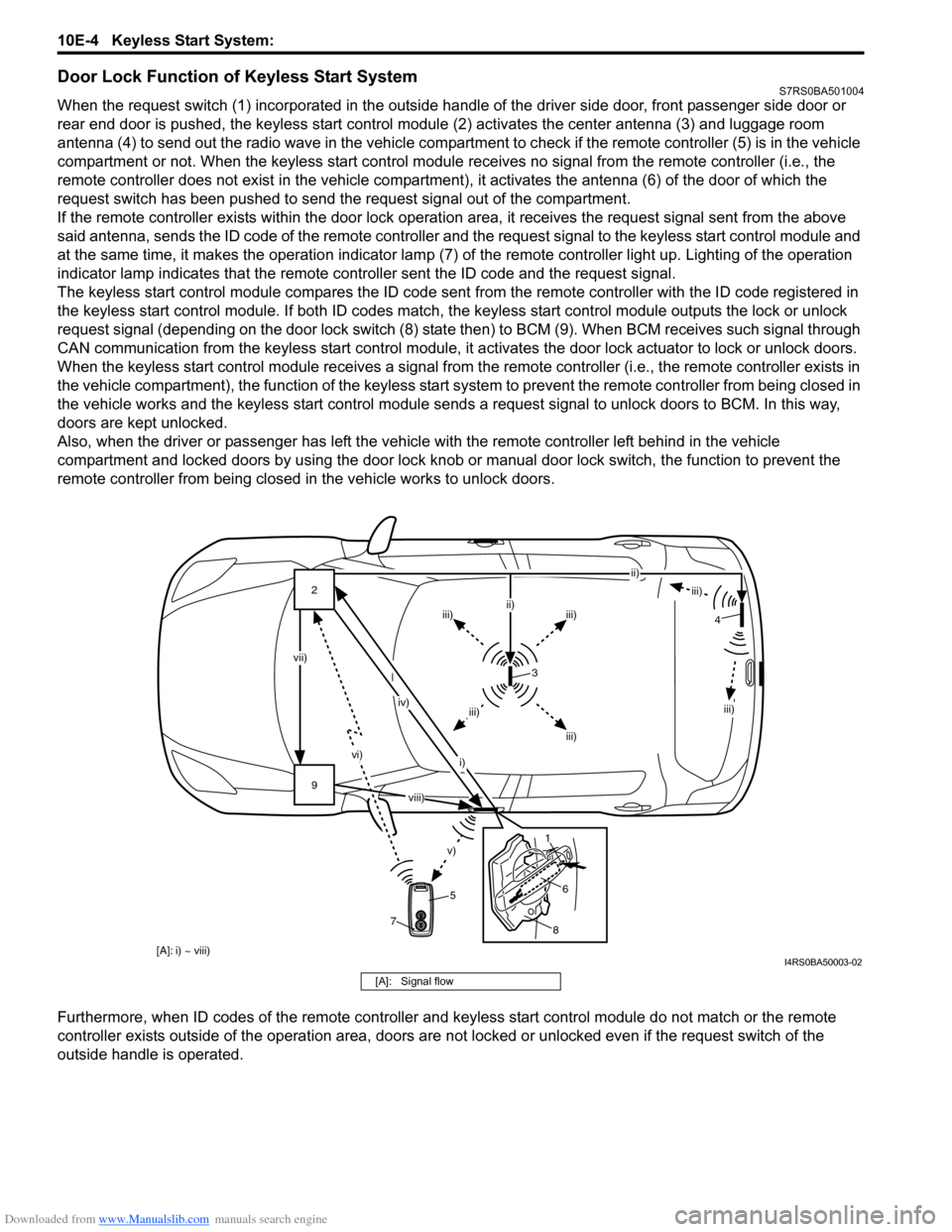
When the request switch (1) incorporated in the outside handle of the driver side door, front passenger side door or
rear end door is pushed, the keyless start control modul e (2) activates the center antenna (3) and luggage room
antenna (4) to send out the radio wave in the vehicle compartm ent to check if the remote controller (5) is in the vehicle
compartment or not. When the keyless start control module receives no signal from the remote controller (i.e., the
remote controller does not exist in the vehicle compartment) , it activates the antenna (6) of the door of which the
request switch has been pushed to send the request signal out of the compartment.
If the remote controller exists within the door lock operati on area, it receives the request signal sent from the above
said antenna, sends the ID code of the remote controller and the request signal to the keyless start control module and
at the same time, it makes the operatio n indicator lamp (7) of the remote controller light up. Lighting of the operation
indicator lamp indicates that the remote controller sent the ID code and the request signal.
The keyless start control module compares the ID code sent from the remote controller with the ID code registered in
the keyless start control module. If both ID codes match, the keyless start control module outputs the lock or unlock
request signal (depending on the door lock switch (8) stat e then) to BCM (9). When BCM receives such signal through
CAN communication from the keyless start control module, it activates the door lock actuator to lock or unlock doors.
When the keyless start control module receiv es a signal from the remote controller (i.e., the remote controller exists in
the vehicle compartment), the function of the keyless start system to prevent the remote controller from being closed in
the vehicle works and the keyless start control module sends a request signal to unlock doors to BCM. In this way,
doors are kept unlocked.
Also, when the driver or passenger has left the vehicl e with the remote controller left behind in the vehicle
compartment and locked doors by using the door lock knob or manual door lock switch, the function to prevent the
remote controller from being closed in the vehicle works to unlock doors.
Furthermore, when ID codes of the remote controller and keyless start control module do not match or the remote
controller exists outside of the operation area, doors are not locked or unlocked even if the request switch of the
outside handle is operated.
9 2
vi)
v)
vii) iv)
i) ii)
iii)
iii)iii)
ii)
iii)
iii)
iii)
3
5
8
6
1 4
7
[A]: i) ~ viii)
viii)
I4RS0BA50003-02
[A]: Signal flow
Page 1470 of 1496
Downloaded from www.Manualslib.com manuals search engine 10E-8 Keyless Start System:
Diagnostic Information and Procedures
Precautions in Diagnosing TroublesS7RS0BA504001
• The keyless start system executes data transmission/reception by means of th e radio wave. Therefore,
proper operation may not be obtained if use of the
door lock function and engine start function of the
keyless start system is attempted near the place
where strong radio wave is emitted (TV and radio
broadcasting stations, etc.).
• Diagnostic information stored in keyless start control
module memory can be checked only by key indicator
lamp.
• Be sure to use the trouble diagnosis procedure as described in “Keyless Start System Check”. Failure to
follow it may result in incorrect diagnosis. (Some other
DTC may be stored by mistake in the memory of
keyless start control module during inspection.)
• Be sure to read “Precautions for Electrical Circuit Service in Section 00” befo re inspection and observe
what is written there.
• Communication of ECM, BCM, TCM (A/T model), ABS control module, keyless start control module and
combination meter is estab lished by CAN (Controller
Area Network). (For detail of CAN communication for
keyless start control module, refer to “CAN
Communication System Description”). Therefore,
handle CAN communication line with care referring to
“Precaution for CAN Communication System in
Section 00”. • Replacement of the keyless start control module
When keyless start control module is replaced with
new one, make sure that r egister remote controller ID
code to keyless start co ntrol module correctly
according to “Registration Procedure for Remote
Controller ID Code”.
• Keyless start control module substitution When the keyless start control module used in
another vehicle was installed in the vehicle, register
the ID code of the remote controller in the keyless
start control module as well as the ignition key
transponder code fo r the immobilizer control system in
ECM. For the registration procedure of the ignition key
transponder code, refer to “Registration of the Ignition
Key in Section 10C”.
Self-Diagnosis FunctionS7RS0BA504002
The keyless start control module has self-diagnosis
function to monitor the system components and circuits
while the keyless start system is at work. When the
keyless start control module detects an abnormality in
the system, it saves the ar ea where such abnormality
has occurred as a DTC in its memory. The DTC stored in
memory of the keyless start control module is indicated
by the key indicator lamp in the combination meter
flashing in a specific pattern. For DTC indication, refer to
“DTC Check” and for the clearing procedure, to “DTC
Clearance”.
Keyless Start System Diagnosis IntroductionS7RS0BA504003
To ensure that the trouble diagnosis is done accurately
and smoothly, observe “Precautions in Diagnosing
Troubles” and follow “Keyless Start System Check”.
Keyless Start System CheckS7RS0BA504004
Step Action YesNo
1 1) Record details of the problem. For your record, use of a questionnaire form will facilit ate collecting information for
proper analysis and diagnosis.
2) Check if the problem described in “Customer Questionnaire (Example)” actually occurs in the vehicle.
(This step should be performed with the customer if
possible.)
Perform “Keyless Start System Operation Inspection”
procedure to check if the symptom which has occurred is
abnormal or not.
3) Check for DTC referring to “DTC Check”, and then record DTC(s).
4) Clear DTC referring to “DTC Clearance” if any DTC exists, and then recheck for DTC.
Is any DTC still detected? Go to Step 2.
Go to Step 3.
2 1) Check and repair referring to applicable “DTC Table”. Are check and repair complete? Go to Step 5.
Check and repair
malfunction part(s), and
go to Step 5.