hot air SUZUKI SWIFT 2008 2.G Service Workshop Manual
[x] Cancel search | Manufacturer: SUZUKI, Model Year: 2008, Model line: SWIFT, Model: SUZUKI SWIFT 2008 2.GPages: 1496, PDF Size: 34.44 MB
Page 7 of 1496
Downloaded from www.Manualslib.com manuals search engine Precautions: 00-2
Servicing and Handling
WARNING!
Many of service procedures require
disconnection of “A/BAG” fuse and all air
bag (inflator) module(s) from initiator circuit
to avoid an accidental deployment.
Driver, Passenger, Side and Curtain Air Bag
(Inflator) Modules
• For handling and storage of a live air bag (inflator) module, select a place where the
ambient temperature below 65 °C (150 ° F),
without high humidity and away from
electric noise.
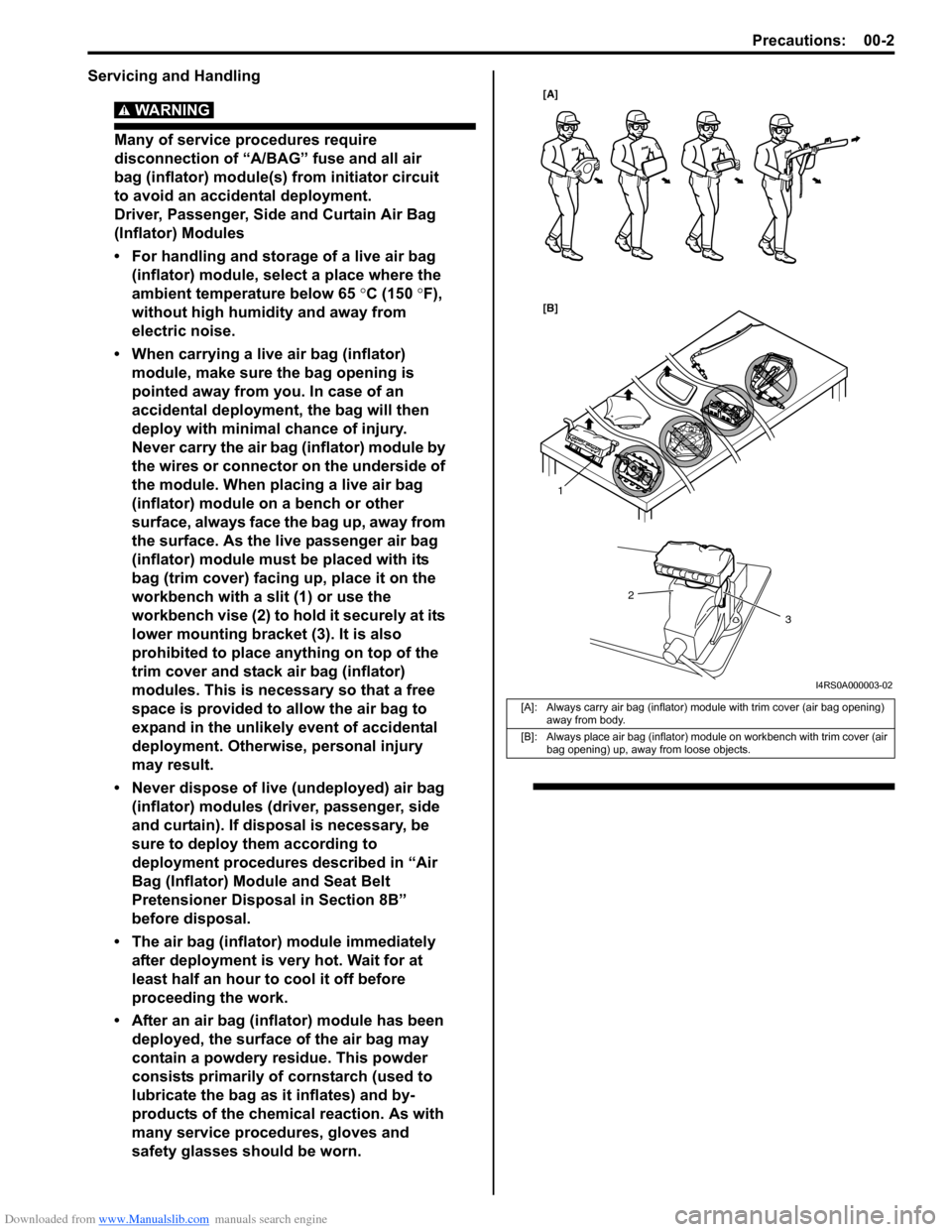
• When carrying a live air bag (inflator) module, make sure the bag opening is
pointed away from you. In case of an
accidental deployment, the bag will then
deploy with minimal chance of injury.
Never carry the air bag (inflator) module by
the wires or connector on the underside of
the module. When placing a live air bag
(inflator) module on a bench or other
surface, always face the bag up, away from
the surface. As the live passenger air bag
(inflator) module must be placed with its
bag (trim cover) facing up, place it on the
workbench with a slit (1) or use the
workbench vise (2) to hold it securely at its
lower mounting bracket (3). It is also
prohibited to place anything on top of the
trim cover and stack air bag (inflator)
modules. This is necessary so that a free
space is provided to allow the air bag to
expand in the unlikely event of accidental
deployment. Otherwise, personal injury
may result.
• Never dispose of live (undeployed) air bag (inflator) modules (driver, passenger, side
and curtain). If disposal is necessary, be
sure to deploy them according to
deployment procedures described in “Air
Bag (Inflator) Module and Seat Belt
Pretensioner Disposal in Section 8B”
before disposal.
• The air bag (inflator) module immediately
after deployment is very hot. Wait for at
least half an hour to cool it off before
proceeding the work.
• After an air bag (inflator) module has been deployed, the surface of the air bag may
contain a powdery residue. This powder
consists primarily of cornstarch (used to
lubricate the bag as it inflates) and by-
products of the chemical reaction. As with
many service procedures, gloves and
safety glasses should be worn.
[A]: Always carry air bag (inflator) module with trim cover (air bag opening) away from body.
[B]: Always place air bag (inflator) module on workbench with trim cover (air bag opening) up, away from loose objects.
1
2
3
[A]
[B]
I4RS0A000003-02
Page 8 of 1496
Downloaded from www.Manualslib.com manuals search engine 00-3 Precautions:
WARNING!
SDM
• For handling and storage of a SDM, select a place where the ambient temperature
below 65 °C (150 °F), without high humidity
and away from electric noise.
• During service procedures, be very careful when handling a Sensing and Diagnostic
Module (SDM). Never strike or jar the SDM.
• Never power up the air bag system when the SDM is not rigidly attached to the
vehicle. All SDM and mounting bracket
fasteners must be carefully torqued and
the arrow must be pointing toward the
front of the vehicle to ensure proper
operation of the air bag system.
The SDM could be activated when powered
while not rigidly att ached to the vehicle
which could cause deployment and result
in personal injury.
WARNING!
Driver and Passenger Seat Belt
Pretensioners
• For handling and storage of a live seat belt pretensioner, select a place where the
ambient temperature below 65 °C (150 ° F),
without high humidity and away from
electric noise.
• Never carry seat belt pretensioner by wire or connector of pretensioner. When
placing a live seat belt pretensioner on the
workbench or some place like that, never
put something on seat belt pretensioner.
Otherwise, personal injury may result.
• Never dispose of live (inactivated) seat belt pretensioners (drive and passenger). If
disposal is necessary, be sure to activate
them according to activation procedures
described in “Air Bag (Inflator) Module and
Seat Belt Pretensioner Disposal in Section
8B” before disposal.
• The seat belt pretensioner immediately after activation is very hot. Wait for at least
half an hour to cool it off before
proceeding the work.
• With many service procedures, gloves and safety glasses should be worn to prevent
any possible irritation of the skin or eyes.
• Even when the accident was light enough not to cause air bags to activate, be sure to inspect system
parts and other related parts according to instructions
under “Repair and Inspection Required after Accident
in Section 8B”.
• When servicing parts other than air bag system, if shocks may be applied to air bag system component
parts, remove those parts beforehand.
• When handling the air bag (inflator) modules (driver, passenger, side and curtain), seat belt pretensioners
(driver and passenger), forward sensor, side sensors
or SDM, be careful not to drop it or apply an impact to
it. If an excessive impact was applied, never attempt
disassembly or repair but replace it with a new one.
• When grease, cleaning agent, oil, water, etc. has got onto air bag (inflator) modules (driver, passenger, side
and curtain) or seat belt pretensioners (drive and
passenger), wipe off immediately with a dry cloth.
• Air bag wire harness is included in floor and instrument panel wire harnesses. Air bag wire
harness branched off from floor and instrument panel
wire harnesses can be identifie d easily as it is covered
with a yellow protection tube and it has yellow
connectors. Be very ca reful when handling it.
• When an open in air bag wire harness, damaged wire harness, connector or terminal is found, replace wire
harness, connectors and terminals as an assembly.
• Do not apply power to the air bag system unless all components are connected or a diagnostic flow
requests it, as this will set a DTC.
• Never use air bag system component parts from another vehicle.
• When using electric welding, be sure to disconnect all air bag (inflator) module connectors and pretensioner
connectors from air bag wire harness respectively.
• Never expose air bag system component parts directly to hot air (drying or baking the vehicle after
painting) or flames.
• WARNING / CAUTION labels are attached on each
part of air bag system components. Be sure to follow
the instructions.
• After vehicle is completely repaired, perform “Air Bag Diagnostic System Check in Section 8B”.
Page 9 of 1496
Downloaded from www.Manualslib.com manuals search engine Precautions: 00-4
General PrecautionsS7RS0B0000002
The WARNING and CAUTION describe some general
precautions that you should observe when servicing a
vehicle. These general precautions apply to many of the
service procedures, and they will not necessarily be
repeated with each procedure to which they apply.
WARNING!
• Whenever raising a vehicle for service, be sure to follow the instructions under
“Vehicle Lifting Points in Section 0A”.
• When it is necessary to do service work with the engine running, make sure that
the parking brake is set fully and the
transmission is in Neutral (for manual
transmission vehicles) or Park (for
automatic transmission vehicles), Keep
hands, hair, clothing, tools, etc. away from
the fan and belts when the engine is
running.
• When it is necessary to run the engine indoors, make sure that the exhaust gas is
forced outdoors.
• Do not perform service work in areas where combustible materials can come in
contact with a hot exhaust system. When
working with toxic or flammable materials
(such as gasoline and refrigerant), make
sure that the area you work in is well-
ventilated.
• To avoid getting burned, keep away from hot metal parts such as the radiator,
exhaust manifold, tail pipe, muffler, etc.
• New and used engine oil can be hazardous. Children and pets may be
harmed by swallowing new or used oil.
Keep new and used oil and used engine oil
filters away from children and pets.
Continuous contact with used engine oil
has been found to cause [skin] cancer in
laboratory animals. Brief contact with used
oil may irritate skin. To minimize your
exposure to used engine oil, wear a long-
sleeve shirt and moisture-proof gloves
(such as dish washing gloves) when
changing engine oil. If engine oil contacts
your skin, wash thoroughly with soap and
water. Launder any clothing or rags if wet
with oil, recycle or properly dispose of
used oil and filters. • Be sure to observe following instructions
when handling service materials such as
fuel, oil, fluid, coolant, grease, sealant,
thread lock cement, etc. Otherwise, your
health may be ruined.
– Whenever handling any of these service materials, wear safety glasses to protect
your eyes. If it gets into your eye, it may
cause inflammation.
– Whenever handling any of these service materials, wear moistu re-proof gloves to
protect your skin. If it adheres to your
skin, it may cause inflammation.
– Do not swallow any of these service materials. It would cause diarrhea or
nausea.
– Keep all these materials out of children’s reach.
• Make sure the bonnet is fully closed and latched before driving. If it is not, it can fly
up unexpectedly during driving,
obstructing your view and resulting in an
accident.
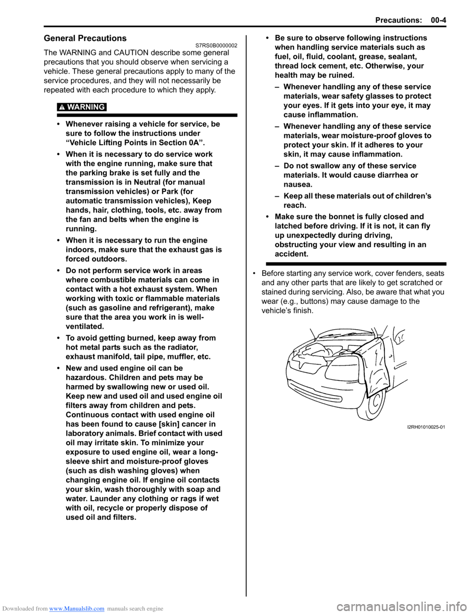
• Before starting any service work, cover fenders, seats and any other parts that are likely to get scratched or
stained during servicing. Also, be aware that what you
wear (e.g., buttons) ma y cause damage to the
vehicle’s finish.
I2RH01010025-01
Page 36 of 1496
Downloaded from www.Manualslib.com manuals search engine 0B-6 Maintenance and Lubrication:
Exhaust System InspectionS7RS0B0206006
WARNING!
To avoid danger of being burned, do not
touch exhaust system when it is still hot.
Any service on exhaust system should be
performed when it is cool.
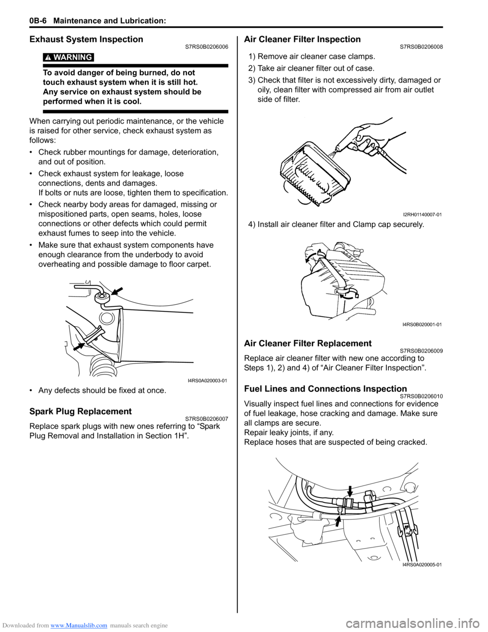
When carrying out periodic maintenance, or the vehicle
is raised for other service, check exhaust system as
follows:
• Check rubber mountings for damage, deterioration, and out of position.
• Check exhaust system for leakage, loose connections, dents and damages.
If bolts or nuts are loose, tighten them to specification.
• Check nearby body areas for damaged, missing or mispositioned parts, ope n seams, holes, loose
connections or other defects which could permit
exhaust fumes to seep into the vehicle.
• Make sure that exhaust system components have enough clearance from the underbody to avoid
overheating and possible damage to floor carpet.
• Any defects should be fixed at once.
Spark Plug ReplacementS7RS0B0206007
Replace spark plugs with new ones referring to “Spark
Plug Removal and Installation in Section 1H”.
Air Cleaner Filter InspectionS7RS0B0206008
1) Remove air cleaner case clamps.
2) Take air cleaner filter out of case.
3) Check that filter is not excessively dirty, damaged or oily, clean filter with compressed air from air outlet
side of filter.
4) Install air cleaner filter and Clamp cap securely.
Air Cleaner Filter ReplacementS7RS0B0206009
Replace air cleaner filter with new one according to
Steps 1), 2) and 4) of “Air Cleaner Filter Inspection”.
Fuel Lines and Connections InspectionS7RS0B0206010
Visually inspect fuel lines and connections for evidence
of fuel leakage, hose cracking and damage. Make sure
all clamps are secure.
Repair leaky joints, if any.
Replace hoses that are suspected of being cracked.
I4RS0A020003-01
I2RH01140007-01
I4RS0B020001-01
I4RS0A020005-01
Page 41 of 1496
Downloaded from www.Manualslib.com manuals search engine Maintenance and Lubrication: 0B-11
Automatic Transaxle Fluid Level InspectionS7RS0B0206028
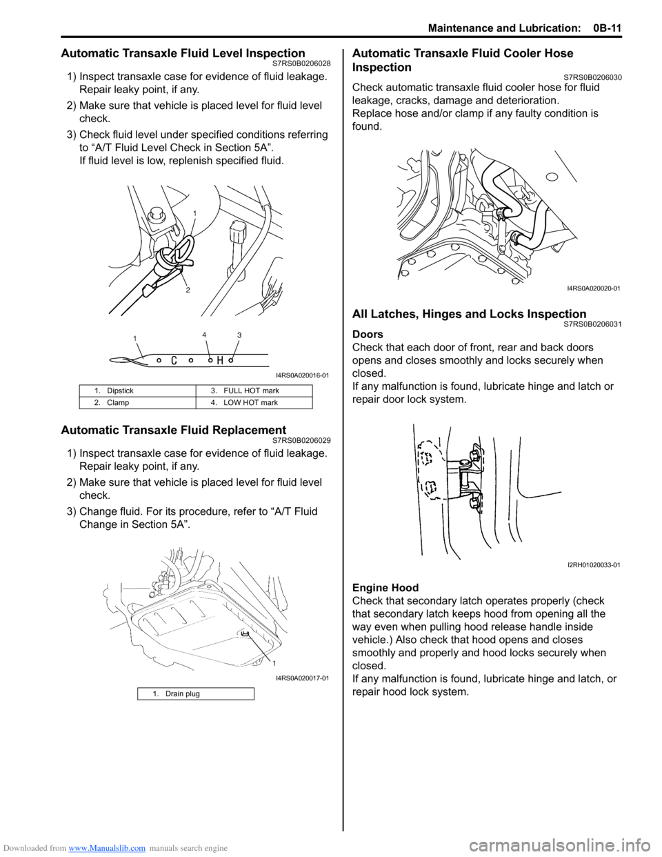
1) Inspect transaxle case for evidence of fluid leakage.Repair leaky point, if any.
2) Make sure that vehicle is placed level for fluid level check.
3) Check fluid level under spec ified conditions referring
to “A/T Fluid Level Check in Section 5A”.
If fluid level is low, replenish specified fluid.
Automatic Transaxle Fluid ReplacementS7RS0B0206029
1) Inspect transaxle case for evidence of fluid leakage. Repair leaky point, if any.
2) Make sure that vehicle is placed level for fluid level check.
3) Change fluid. For its procedure, refer to “A/T Fluid Change in Section 5A”.
Automatic Transaxle Fluid Cooler Hose
Inspection
S7RS0B0206030
Check automatic transaxle fluid cooler hose for fluid
leakage, cracks, damage and deterioration.
Replace hose and/or clamp if any faulty condition is
found.
All Latches, Hinges and Locks InspectionS7RS0B0206031
Doors
Check that each door of front, rear and back doors
opens and closes smoothly and locks securely when
closed.
If any malfunction is found, lubricate hinge and latch or
repair door lock system.
Engine Hood
Check that secondary latch operates properly (check
that secondary latch keeps hood from opening all the
way even when pulling hood release handle inside
vehicle.) Also check that hood opens and closes
smoothly and properly and hood locks securely when
closed.
If any malfunction is found, l ubricate hinge and latch, or
repair hood lock system.
1. Dipstick 3. FULL HOT mark
2. Clamp 4. LOW HOT mark
1. Drain plug
I4RS0A020016-01
I4RS0A020017-01
I4RS0A020020-01
I2RH01020033-01
Page 278 of 1496
Downloaded from www.Manualslib.com manuals search engine 1C-6 Engine Electrical Devices:
APP Sensor Assembly InspectionS7RS0B1306007
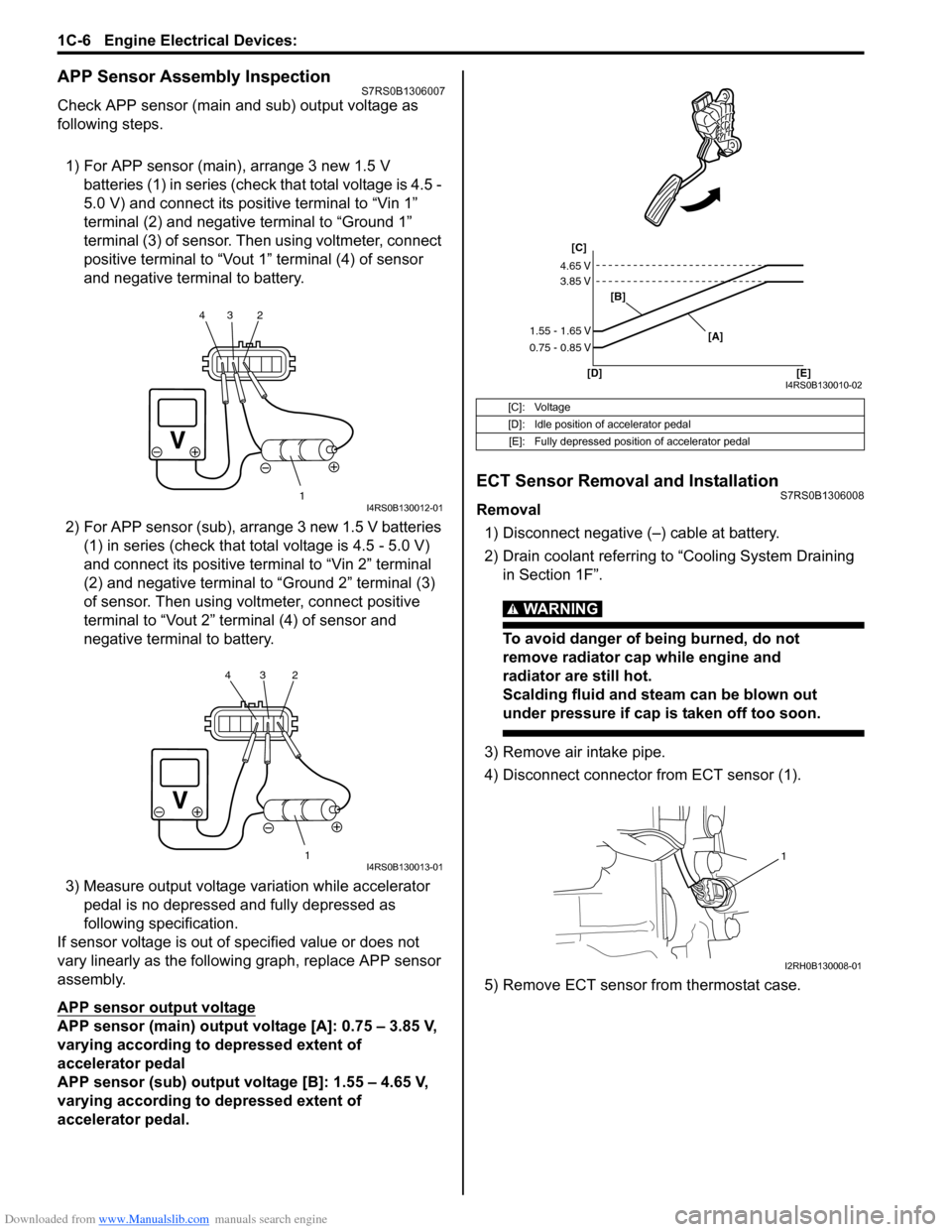
Check APP sensor (main and sub) output voltage as
following steps.
1) For APP sensor (main) , arrange 3 new 1.5 V
batteries (1) in series (check that total voltage is 4.5 -
5.0 V) and connect its positive terminal to “Vin 1”
terminal (2) and negative terminal to “Ground 1”
terminal (3) of sensor. Then using voltmeter, connect
positive terminal to “Vout 1” terminal (4) of sensor
and negative terminal to battery.
2) For APP sensor (s ub), arrange 3 new 1.5 V batteries
(1) in series (check that total voltage is 4.5 - 5.0 V)
and connect its positive terminal to “Vin 2” terminal
(2) and negative terminal to “Ground 2” terminal (3)
of sensor. Then using volt meter, connect positive
terminal to “Vout 2” terminal (4) of sensor and
negative termin al to battery.
3) Measure output voltage variation while accelerator pedal is no depressed and fully depressed as
following specification.
If sensor voltage is out of specified value or does not
vary linearly as the followin g graph, replace APP sensor
assembly.
APP sensor output voltage
APP sensor (main) output voltage [A]: 0.75 – 3.85 V,
varying according to depressed extent of
accelerator pedal
APP sensor (sub) output voltage [B]: 1.55 – 4.65 V,
varying according to depressed extent of
accelerator pedal.
ECT Sensor Removal and InstallationS7RS0B1306008
Removal
1) Disconnect negative (–) cable at battery.
2) Drain coolant referring to “Cooling System Draining in Section 1F”.
WARNING!
To avoid danger of being burned, do not
remove radiator cap while engine and
radiator are still hot.
Scalding fluid and steam can be blown out
under pressure if cap is taken off too soon.
3) Remove air intake pipe.
4) Disconnect connector from ECT sensor (1).
5) Remove ECT sensor from thermostat case.
1
234I4RS0B130012-01
1
234I4RS0B130013-01
[C]: Voltage
[D]: Idle position of accelerator pedal
[E]: Fully depressed position of accelerator pedal
[C]
[B]
[D] [E] [A]
4.65 V
3.85 V
1.55 - 1.65 V
0.75 - 0.85 V
I4RS0B130010-02
1
I2RH0B130008-01
Page 284 of 1496
Downloaded from www.Manualslib.com manuals search engine 1C-12 Engine Electrical Devices:
MAF and IAT Sensor InspectionS7RS0B1306020
CAUTION!
Do not heat up MAF and IAT sensor more
than 100 °C (212 °F). Otherwise, MAF and IAT
sensor will be damaged.
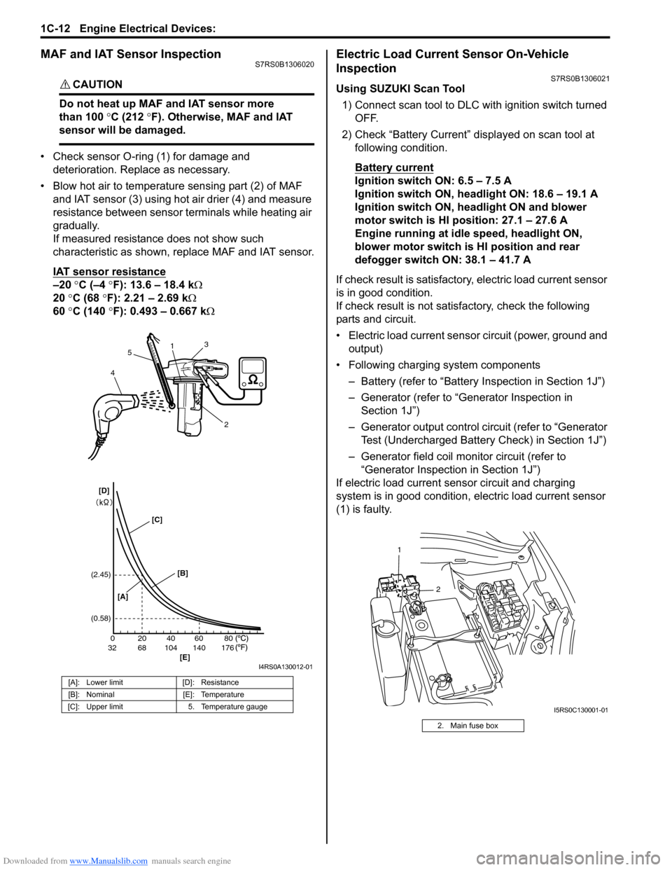
• Check sensor O-ring (1) for damage and deterioration. Replace as necessary.
• Blow hot air to temperature sensing part (2) of MAF and IAT sensor (3) using hot air drier (4) and measure
resistance between sensor terminals while heating air
gradually.
If measured resistance does not show such
characteristic as shown, replace MAF and IAT sensor.
IAT sensor resistance
–20 °C (–4 °F): 13.6 – 18.4 k Ω
20 °C (68 °F): 2.21 – 2.69 k Ω
60 °C (140 °F): 0.493 – 0.667 k Ω
Electric Load Current Sensor On-Vehicle
Inspection
S7RS0B1306021
Using SUZUKI Scan Tool
1) Connect scan tool to DLC with ignition switch turned OFF.
2) Check “Battery Current” displayed on scan tool at following condition.
Battery current
Ignition switch ON: 6.5 – 7.5 A
Ignition switch ON, headlight ON: 18.6 – 19.1 A
Ignition switch ON, headlight ON and blower
motor switch is HI position: 27.1 – 27.6 A
Engine running at idle speed, headlight ON,
blower motor switch is HI position and rear
defogger switch ON: 38.1 – 41.7 A
If check result is satisfactory, electric load current sensor
is in good condition.
If check result is not satisf actory, check the following
parts and circuit.
• Electric load current sensor circuit (power, ground and output)
• Following charging system components
– Battery (refer to “Battery Inspection in Section 1J”)
– Generator (refer to “Generator Inspection in Section 1J”)
– Generator output control ci rcuit (refer to “Generator
Test (Undercharged Battery Check) in Section 1J”)
– Generator field coil monitor circuit (refer to “Generator Inspection in Section 1J”)
If electric load current sensor circuit and charging
system is in good condition, electric load current sensor
(1) is faulty.
[A]: Lower limit [D]: Resistance
[B]: Nominal [E]: Temperature
[C]: Upper limit 5. Temperature gauge
200
6832104 140 17640 60 80
(2.45)
(0.58)
1
2
3
4 5
[A] [B]
[E]
[C]
[D]
I4RS0A130012-01
2. Main fuse box
2
1
I5RS0C130001-01
Page 291 of 1496
Downloaded from www.Manualslib.com manuals search engine Engine Mechanical: 1D-6
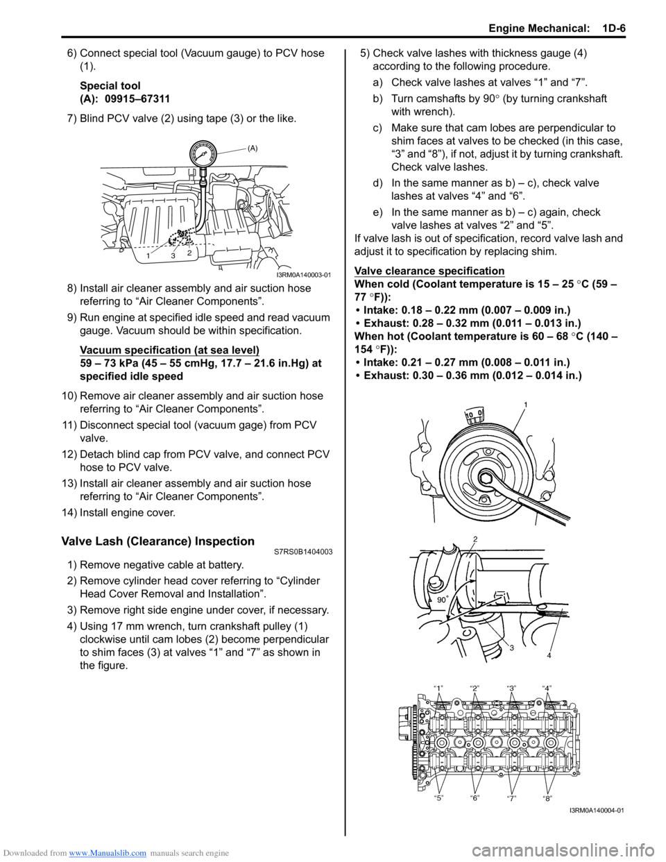
6) Connect special tool (Vacuum gauge) to PCV hose (1).
Special tool
(A): 09915–67311
7) Blind PCV valve (2) using tape (3) or the like.
8) Install air cleaner assembly and air suction hose referring to “Air Cleaner Components”.
9) Run engine at specified idle speed and read vacuum gauge. Vacuum should be within specification.
Vacuum specification (at sea level)
59 – 73 kPa (45 – 55 cmHg, 17.7 – 21.6 in.Hg) at
specified idle speed
10) Remove air cleaner assembly and air suction hose referring to “Air Cleaner Components”.
11) Disconnect special tool (vacuum gage) from PCV valve.
12) Detach blind cap from PCV valve, and connect PCV hose to PCV valve.
13) Install air cleaner assembly and air suction hose referring to “Air Cleaner Components”.
14) Install engine cover.
Valve Lash (Clearance) InspectionS7RS0B1404003
1) Remove negative cable at battery.
2) Remove cylinder head cover referring to “Cylinder Head Cover Removal and Installation”.
3) Remove right side engine under cover, if necessary.
4) Using 17 mm wrench, turn crankshaft pulley (1) clockwise until cam lobes (2) become perpendicular
to shim faces (3) at valves “1” and “7” as shown in
the figure. 5) Check valve lashes with thickness gauge (4)
according to the following procedure.
a) Check valve lashes at valves “1” and “7”.
b) Turn camshafts by 90 ° (by turning crankshaft
with wrench).
c) Make sure that cam lobes are perpendicular to shim faces at valves to be checked (in this case,
“3” and “8”), if not, adjust it by turning crankshaft.
Check valve lashes.
d) In the same manner as b) – c), check valve
lashes at valves “4” and “6”.
e) In the same manner as b) – c) again, check valve lashes at valves “2” and “5”.
If valve lash is out of specification, record valve lash and
adjust it to specification by replacing shim.
Valve clearance specification
When cold (Coolant te mperature is 15 – 25 °C (59 –
77 °F)):
• Intake: 0.18 – 0.22 mm (0.007 – 0.009 in.)
• Exhaust: 0.28 – 0.32 mm (0.011 – 0.013 in.)
When hot (Coolant temperature is 60 – 68 °C (140 –
154 °F)):
• Intake: 0.21 – 0.27 mm (0.008 – 0.011 in.)
• Exhaust: 0.30 – 0.36 mm (0.012 – 0.014 in.)
(A)
13 2
I3RM0A140003-01
I3RM0A140004-01
Page 354 of 1496
Downloaded from www.Manualslib.com manuals search engine 1E-2 Engine Lubrication System:
Diagnostic Information and Procedures
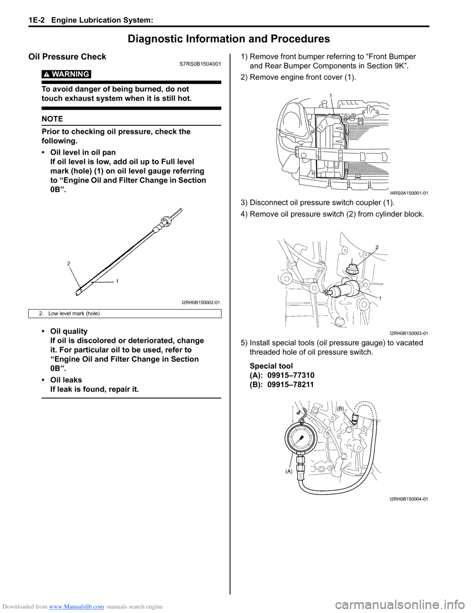
Oil Pressure CheckS7RS0B1504001
WARNING!
To avoid danger of being burned, do not
touch exhaust system when it is still hot.
NOTE
Prior to checking oil pressure, check the
following.
• Oil level in oil pan
If oil level is low, add oil up to Full level
mark (hole) (1) on oil level gauge referring
to “Engine Oil and Filter Change in Section
0B”.
• Oil quality If oil is discolored or deteriorated, change
it. For particular oil to be used, refer to
“Engine Oil and Filter Change in Section
0B”.
• Oil leaks If leak is found, repair it.
1) Remove front bumper referring to “Front Bumper and Rear Bumper Components in Section 9K”.
2) Remove engine front cover (1).
3) Disconnect oil pressure switch coupler (1).
4) Remove oil pressure swit ch (2) from cylinder block.
5) Install special tools (oil pressure gauge) to vacated threaded hole of oil pressure switch.
Special tool
(A): 09915–77310
(B): 09915–78211
2. Low level mark (hole)
I2RH0B150002-01
1
I4RS0A150001-01
I2RH0B150003-01
I2RH0B150004-01
Page 425 of 1496
Downloaded from www.Manualslib.com manuals search engine Exhaust System: 1K-2
Repair Instructions
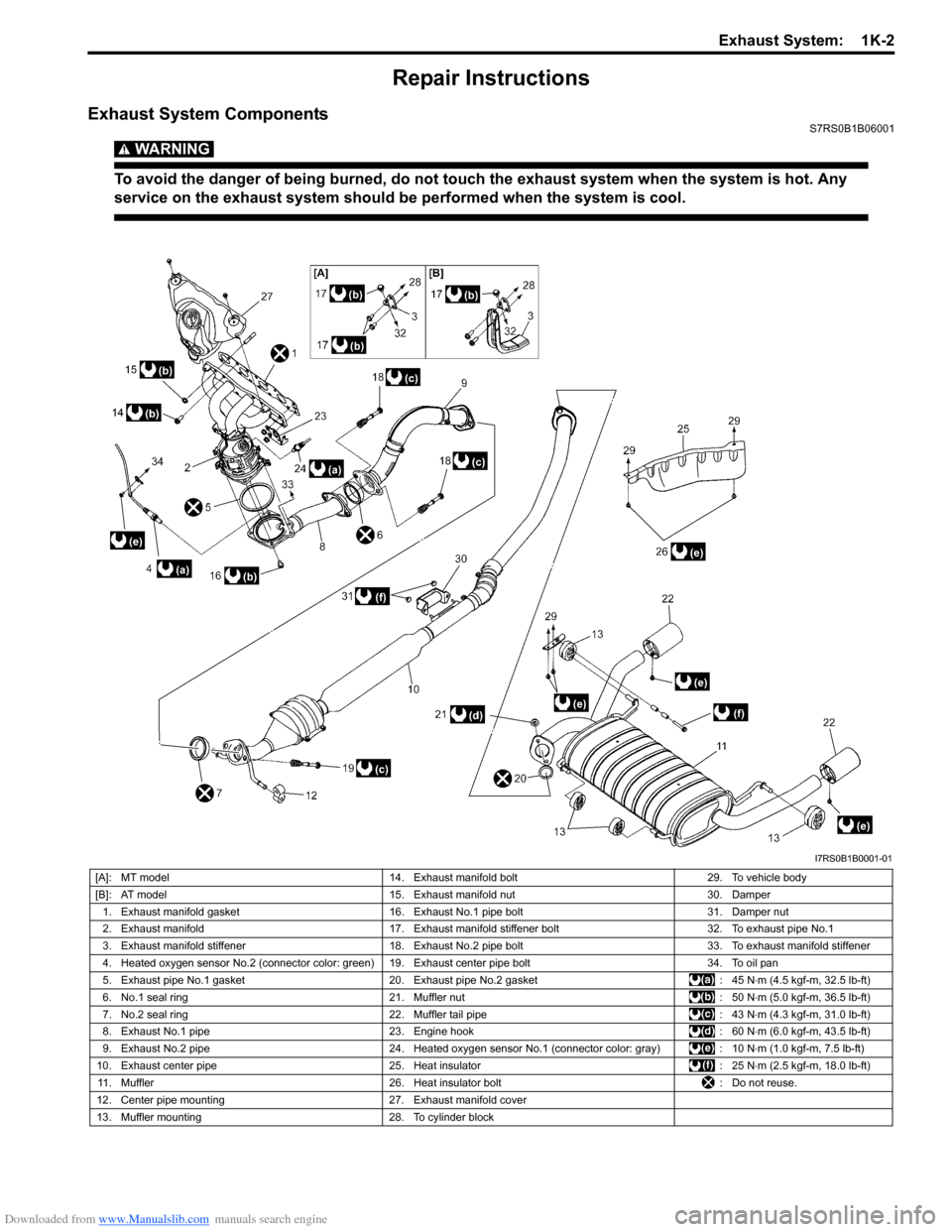
Exhaust System ComponentsS7RS0B1B06001
WARNING!
To avoid the danger of being burned, do not touch the exhaust system when the system is hot. Any
service on the exhaust system should be performed when the system is cool.
I7RS0B1B0001-01
[A]: MT model14. Exhaust manifold bolt 29. To vehicle body
[B]: AT model 15. Exhaust manifold nut 30. Damper
1. Exhaust manifold gasket 16. Exhaust No.1 pipe bolt 31. Damper nut
2. Exhaust manifold 17. Exhaust manifold stiffener bolt 32. To exhaust pipe No.1
3. Exhaust manifold stiffener 18. Exhaust No.2 pipe bolt 33. To exhaust manifold stiffener
4. Heated oxygen sensor No.2 (connector color: green) 19. Exhaust center pipe bolt 34. To oil pan
5. Exhaust pipe No.1 gasket 20. Exhaust pipe No.2 gasket : 45 N⋅m (4.5 kgf-m, 32.5 lb-ft)
6. No.1 seal ring 21. Muffler nut : 50 N⋅m (5.0 kgf-m, 36.5 lb-ft)
7. No.2 seal ring 22. Muffler tail pipe : 43 N⋅m (4.3 kgf-m, 31.0 lb-ft)
8. Exhaust No.1 pipe 23. Engine hook : 60 N⋅m (6.0 kgf-m, 43.5 lb-ft)
9. Exhaust No.2 pipe 24. Heated oxygen sensor No.1 (connector color: gray) : 10 N⋅m (1.0 kgf-m, 7.5 lb-ft)
10. Exhaust center pipe 25. Heat insulator : 25 N⋅m (2.5 kgf-m, 18.0 lb-ft)
11. Muffler 26. Heat insulator bolt : Do not reuse.
12. Center pipe mounting 27. Exhaust manifold cover
13. Muffler mounting 28. To cylinder block