sign SUZUKI SWIFT 2017 5.G Workshop Manual
[x] Cancel search | Manufacturer: SUZUKI, Model Year: 2017, Model line: SWIFT, Model: SUZUKI SWIFT 2017 5.GPages: 336, PDF Size: 6.24 MB
Page 181 of 336
5-54
OTHER CONTROLS AND EQUIPMENT
74LH0-74E
(with spare tyre)
74LHT0528
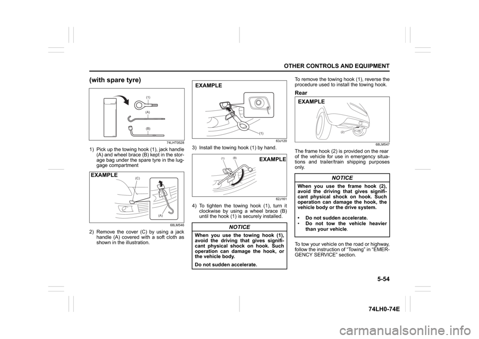
1) Pick up the towing hook (1), jack handle
(A) and wheel brace (B) kept in the stor-
age bag under the spare tyre in the lug-
gage compartment
68LM546
2) Remove the cover (C) by using a jack
handle (A) covered with a soft cloth as
shown in the illustration.
63J120
3) Install the towing hook (1) by hand.
62J161
4) To tighten the towing hook (1), turn it
clockwise by using a wheel brace (B)
until the hook (1) is securely installed.To remove the towing hook (1), reverse the
procedure used to install the towing hook.
Rear
68LM547
The frame hook (2) is provided on the rear
of the vehicle for use in emergency situa-
tions and trailer/train shipping purposes
only.
To tow your vehicle on the road or highway,
follow the instruction of “Towing” in “EMER-
GENCY SERVICE” section.
(1)(A)(B)
(C)
(A)
EXAMPLE
NOTICE
When you use the towing hook (1),
avoid the driving that gives signifi-
cant physical shock on hook. Such
operation can damage the hook, or
the vehicle body.
Do not sudden accelerate.
(1)
EXAMPLE
(1)
(B)
EXAMPLE
NOTICE
When you use the frame hook (2),
avoid the driving that gives signifi-
cant physical shock on hook. Such
operation can damage the hook, the
vehicle body or the drive system.
Do not sudden accelerate.
Do not tow the vehicle heavier
than your vehicle.
(2)
EXAMPLE
Page 182 of 336
5-55OTHER CONTROLS AND EQUIPMENT
74LH0-74E
Other Hooks
74LHT0536
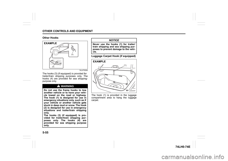
The hooks (3) (if equipped) is provided for
trailer/train shipping purposes only. The
hooks (4) are provided for sea shipping-
purpose only.
Luggage Carpet Hook (if equipped)The hook (1) is provided in the luggage
compartment area to hang the luggage
carpet.
WA R N I N G
Do not use the frame hooks to tow
another vehicle or to have your vehi-
cle towed on the road or highway.
The hook (1) is designed for use in
emergency situations only, such as if
your vehicle or another vehicle gets
stuck in deep mud or snow. The hook
(2) is designed for use in emergency
situations and trailer/train shipping
only.
The hooks (3) (if equipped) is pro-
vided for trailer/train shipping pur-
poses only. The hooks (4) are
provided for sea shipping purpose
only.
(4)(3)
EXAMPLE
NOTICE
Never use the hooks (1) for trailer/
train shipping and sea shipping pur-
poses to prevent damage to the vehi-
cle.
(1)
EXAMPLE
Page 184 of 336
6-1VEHICLE LOADING AND TOWING
74LH0-74E
Vehicle LoadingYour vehicle was designed for specific
weight capacities. The weight capacities of
your vehicle are indicated by the Gross
Vehicle Weight Rating (GVWR) and the
Gross Axle Weight Rating (GAWR, front
and rear). The GVWR and GAWR (front
and rear) are listed in the “SPECIFICA-
TIONS” section.
GVWR – Maximum permissible overall
weight of the fully loaded vehicle (including
all the occupants, accessories and cargo
plus the trailer nose weight if towing a
trailer).
GAWR – (Front and Rear) Maximum per-
missible weight on an individual axle.
Actual weight of the loaded vehicle and
actual loads at the front and rear axles can
only be determined by weighing the vehi-
cle. Compare these weights to the GVWR
and GAWR (front and rear). If the gross
vehicle weight or the load on either axle
exceeds these ratings, you must remove
enough weight to bring the load down to
the rated capacity.
Trailer TowingYour MARUTI SUZUKI was originally
designed to carry people and a normal
amount of cargo, not to tow a trailer.
MARUTI SUZUKI does not recommend
you use your vehicle to tow a trailer. Tow-
ing a trailer can adversely affect handling,
durability,
Some countries have regulations which
specifically allow trailer towing up to a
specified maximum trailer weight (regis-
tered or statutory towing capacity, which-
ever is smaller); vehicles sold in these
countries can be used to tow a light trailer,
provided the trailer does not exceed the
maximum trailer weight specified in the
country’s regulations.
If you use your MARUTI SUZUKI to tow a
trailer, you should always observe the
requirements and recommendations in this
section. If you intend to tow a trailer, it is
essential to select a trailer and trailer tow-
ing equipment which are compatible. A
reputable towing specialist can help you.
and fuel economy.
WA R N I N G
Never overload your vehicle. The
gross vehicle weight (sum of the
weights of the vehicle, all the occu-
pants, accessories, cargo plus trailer
nose weight if towing a trailer) must
never exceed the Gross Vehicle
Weight Rating (GVWR). In addition,
never distribute a load so that the
weight on either the front or rear axle
exceeds the Gross Axle Weight Rat-
ing (GAWR).
WA R N I N G
Always distribute cargo evenly. To
avoid personal injury or damage to
your vehicle, always secure cargo to
prevent it from shifting if the vehicle
moves suddenly. Place heavier
objects on the floor and as far for-
ward in the cargo area as possible.
Never pile cargo higher than the top
of the seat backs.
NOTICE
Trailer towing puts additional stress
on the engine, drive train, and brakes
of your vehicle. Never tow a trailer
during the first 960 km (600 miles) of
vehicle operation.
Vehicle Loading: 11
Trailer Towing: 5, 11
Page 186 of 336
6-3VEHICLE LOADING AND TOWING
74LH0-74E
Additional Trailer Towing Warnings
WA R N I N G
Connect trailer lights and hook up
safety chains every time you tow.
NOTICE
Because towing a trailer puts addi-
tional stress on your vehicle, more
frequent maintenance will be
required than under normal driving
conditions.
WA R N I N G
Your vehicle will handle differently
when towing a trailer. For your safety
and the safety of others, you should
observe the following precautions:
Practice turning, stopping, and
reversing before you begin towing
in traffic. Do not tow in traffic until
you are confident that you can han-
dle the vehicle and trailer safely.
Never exceed towing speed limits
or 80 km/h (50 mph), whichever is
lower.
Never drive at a speed that causes
shaking or swaying of the trailer. If
you notice even the slightest sign
of shaking or swaying, slow down.
When roads are wet, slippery or
rough, drive at a slower speed than
you would on dry, smooth roads.
Failure to slow down when road
conditions are bad can result in
loss of control.
Always have someone guide you
when reversing.
Allow adequate stopping distance.
Stopping distance is increased
when you tow a trailer. For each 16
(Continued)
WA R N I N G
(Continued)
km/h (10 mph) of speed, allow at
least one vehicle and trailer length
between you and the vehicle ahead.
Follow at a greater distance if roads
are wet or slippery.
If the trailer has over-run brakes,
apply the brakes gradually to avoid
snatching caused by the trailer
wheels locking.
Slow down before corners and
maintain a steady speed while cor-
nering. Deceleration or accelera-
tion while cornering can result in
loss of control. Remember that a
larger than normal turning radius is
needed because the trailer wheels
will be closer than vehicle wheels
to the inside of the turn.
Avoid sudden acceleration and
stopping of the vehicle. Do not
make quick maneuvers unless they
are necessary.
Slow down in cross winds and be
prepared for gusts of wind from
large passing vehicles.
(Continued)
Page 187 of 336
6-4
VEHICLE LOADING AND TOWING
74LH0-74E
60A186
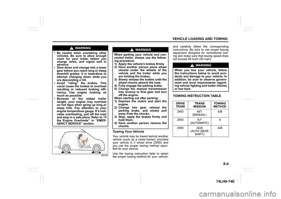
Towing Your VehicleYour vehicle may be towed behind another
vehicle (such as a motor-home), provided
your vehicle is 2 wheel drive (2WD) and
you use the proper towing method speci-
fied for your vehicle.
Use the towing instruction table to select
the proper towing method for your vehicle,and carefully follow the corresponding
instructions. Be sure to use proper towing
equipment designed for recreational tow-
ing and make sure that towing speed does
not exceed 90 km/h (55 mph)
TOWING INSTRUCTION TABLE
WA R N I N G
Be careful when overtaking other
vehicles. Be sure to allow enough
room for your trailer before you
change lanes, and signal well in
advance. Slow down and change into a lower
gear before you reach long or steep
downhill grades. It is hazardous to
attempt changing down while you
are descending a hill.
Avoid “riding” the brakes. This
could cause the brakes to overheat
resulting in reduced braking effi-
ciency. Use engine braking as
much as possible.
Because of the added trailer
weight, your engine may overheat
on hot days when going up long or
steep hills. Pay attention to your
engine temperature gauge. If it indi-
cates overheating, pull off the road
and stop in a safe place. Refer to “If
the Engine Overheats” in “EMER-
GENCY SERVICE” section.
WA R N I N G
When parking your vehicle and con-
nected trailer, always use the follow-
ing procedure:
1) Apply the vehicle’s brakes firmly.
2) Have another person place wheel
chocks under the wheels of the
vehicle and the trailer while you
are holding the brakes.
3) Slowly release the brakes until the
wheel chocks absorb the load.
4) Fully engage the parking brake.
5) Change the manual transmission
into reverse or first gear and turn
off the engine.
When starting out after parking:
1) Depress the clutch and start the
engine.
2) Change into gear, release the
parking brake, and slowly pull
away from the chocks.
3) Stop, apply the brakes firmly and
hold them.
4) Have another person remove the
chocks.
WA R N I N G
When you tow your vehicle, follow
the instructions below to avoid acci-
dents and damage to your vehicle. In
addition, be sure to observe govern-
ment and local requirements regard-
ing vehicle lighting and trailer hitches
or tow bars.
DRIVE
TRAINTRANS
MISSIONTOWING
METHOD
2WD M/T
(MANUAL)A/B
2WD A/T
(AUTOMATIC)A
2WD AGS
(AUTO GEAR
SHIFT)A/B
Page 210 of 336
7-19INSPECTION AND MAINTENANCE
74LH0-74E
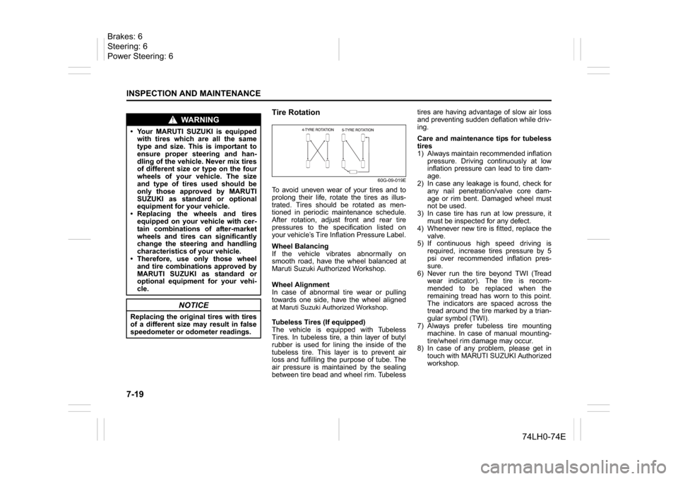
Tire Rotation
60G-09-019E
To avoid uneven wear of your tires and to
prolong their life, rotate the tires as illus-
trated. Tires should be rotated as men-
tioned in periodic maintenance schedule.
After rotation, adjust front and rear tire
pressures to the specification listed on
your vehicle’s Tire Inflation Pressure Label.
Wheel Balancing
If the vehicle vibrates abnormally on
smooth road, have the wheel balanced at
Maruti Suzuki Authorized Workshop.
Wheel Alignment
In case of abnormal tire wear or pulling
towards one side, have the wheel aligned
at Maruti Suzuki Authorized Workshop.Tubeless Tires (If equipped)
The vehicle is equipped with Tubeless
Tires. In tubeless tire, a thin layer of butyl
rubber is used for lining the inside of the
tubeless tire. This layer is to prevent air
loss and fulfilling the purpose of tube. The
air pressure is maintained by the sealing
between tire bead and wheel rim. Tubelesstires are having advantage of slow air loss
and preventing sudden deflation while driv-
ing.
Care and maintenance tips for tubeless
tires
1) Always maintain recommended inflation
pressure. Driving continuously at low
inflation pressure can lead to tire dam-
age.
2) In case any leakage is found, check for
any nail penetration/valve core dam-
age or rim bent. Damaged wheel must
not be used.
3) In case tire has run at low pressure, it
must be inspected for any defect.
4) Whenever new tire is fitted, replace the
valve.
5) If continuous high speed driving is
required, increase tires pressure by 5
psi over recommended inflation pres-
sure.
6) Never run the tire beyond TWI (Tread
wear indicator). The tire is recom-
mended to be replaced when the
remaining tread has worn to this point.
The indicators are spaced across the
tread around the tire marked by a trian-
gular symbol (TWI).
7) Always prefer tubeless tire mounting
machine. In case of manual mounting-
tire/wheel rim damage may occur.
8) In case of any problem, please get in
touch with MARUTI SUZUKI Authorized
workshop.
WA R N I N G
Your MARUTI SUZUKI is equipped
with tires which are all the same
type and size. This is important to
ensure proper steering and han-
dling of the vehicle. Never mix tires
of different size or type on the four
wheels of your vehicle. The size
and type of tires used should be
only those approved by MARUTI
SUZUKI as standard or optional
equipment for your vehicle.
Replacing the wheels and tires
equipped on your vehicle with cer-
tain combinations of after-market
wheels and tires can significantly
change the steering and handling
characteristics of your vehicle.
Therefore, use only those wheel
and tire combinations approved by
MARUTI SUZUKI as standard or
optional equipment for your vehi-
cle.
NOTICE
Replacing the original tires with tires
of a different size may result in false
speedometer or odometer readings.
Brakes: 6
Steering: 6
Power Steering: 6
Page 214 of 336
7-23INSPECTION AND MAINTENANCE
74LH0-74E
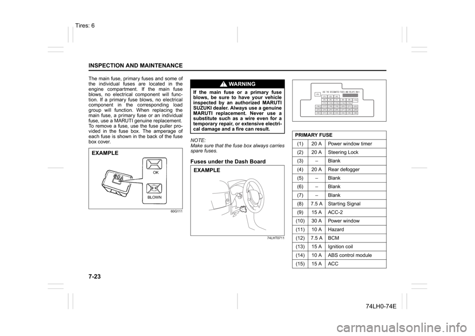
The main fuse, primary fuses and some of
the individual fuses are located in the
engine compartment. If the main fuse
blows, no electrical component will func-
tion. If a primary fuse blows, no electrical
component in the corresponding load
group will function. When replacing the
main fuse, a primary fuse or an individual
fuse, use a MARUTI genuine replacement.
To remove a fuse, use the fuse puller pro-
vided in the fuse box. The amperage of
each fuse is shown in the back of the fuse
box cover.
60G111
NOTE:
Make sure that the fuse box always carries
spare fuses.Fuses under the Dash Board
74LHT0711
EXAMPLE
BLOWNOK
WA R N I N G
If the main fuse or a primary fuse
blows, be sure to have your vehicle
inspected by an authorized MARUTI
SUZUKI dealer. Always use a genuine
MARUTI replacement. Never use a
substitute such as a wire even for a
temporary repair, or extensive electri-
cal damage and a fire can result.EXAMPLE
PRIMARY FUSE
(1) 20 A Power window timer
(2) 20 A Steering Lock
(3) – Blank
(4) 20 A Rear defogger
(5) – Blank
(6) – Blank
(7) – Blank
(8) 7.5 A Starting Signal
(9) 15 A ACC-2
(10) 30 A Power window
(11) 10 A Hazard
(12) 7.5 A BCM
(13) 15 A Ignition coil
(14) 10 A ABS control module
(15) 15 A ACC
(3)
(12)(10)
(13)
(36) (1) (2) (4)
(5)(6)
(7) (8)(9)
(11) (14) (15)
(16) (17) (18) (19) (20) (21) (22)
(23) (24) (25) (26) (27) (28) (29)
(30) (31) (32) (33) (34) (35)
Tires: 6
Page 215 of 336
7-24
INSPECTION AND MAINTENANCE
74LH0-74E
81A283
Bulb Replacement
(16) – Blank
(17) 15 A Horn
(18) 10 A Stop light
(19) 10 A Air bag
(20) 10 A Back-up light
(21) 15 A Rear wiper / Washer
(22) 25 A Front wiper
(23) 7.5 A Dome light
(24) – Blank
(25) 7.5 A RR fog lamp
(26) – Blank
(27) 7.5 A Ignition-1 signal
(28) 15 A Radio 2
(29) – Blank
(30) 15 A Radio
(31) 10 A Tail lamp
(32) 20 A D/L
(33) – Blank
(34) 10 A Meter
(35) 7.5 A Ignition-2 signal
(36) – Blank
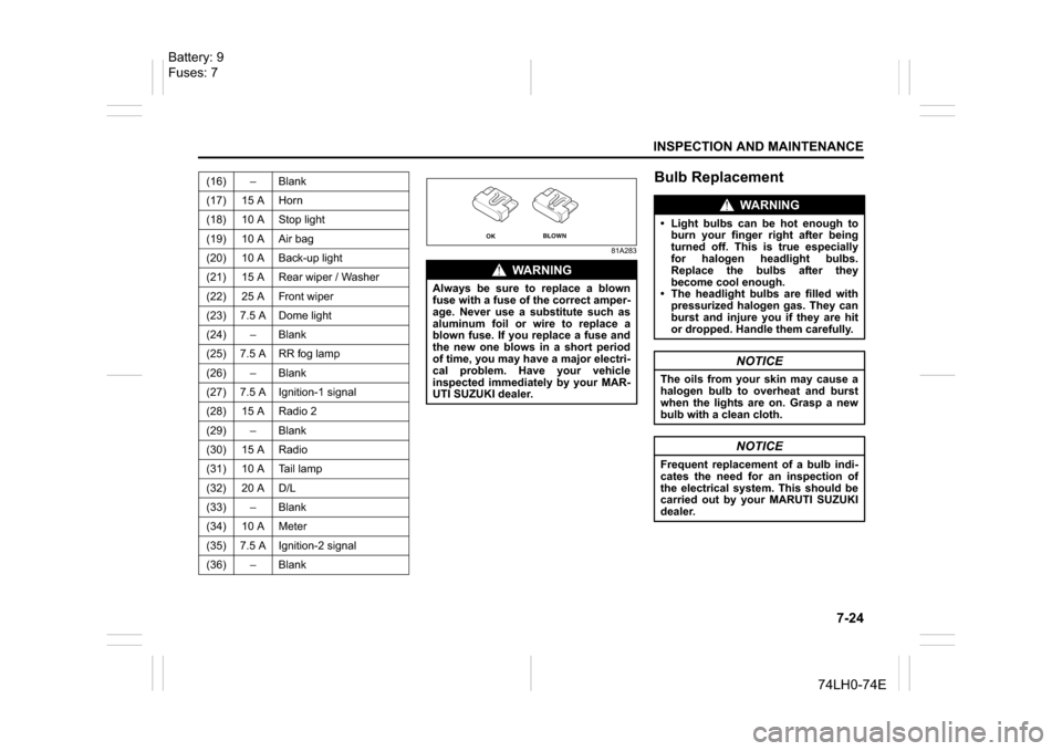
WA R N I N G
Always be sure to replace a blown
fuse with a fuse of the correct amper-
age. Never use a substitute such as
aluminum foil or wire to replace a
blown fuse. If you replace a fuse and
the new one blows in a short period
of time, you may have a major electri-
cal problem. Have your vehicle
inspected immediately by your MAR-
UTI SUZUKI dealer.
OK
BLOWN
WA R N I N G
Light bulbs can be hot enough to
burn your finger right after being
turned off. This is true especially
for halogen headlight bulbs.
Replace the bulbs after they
become cool enough.
The headlight bulbs are filled with
pressurized halogen gas. They can
burst and injure you if they are hit
or dropped. Handle them carefully.
NOTICE
The oils from your skin may cause a
halogen bulb to overheat and burst
when the lights are on. Grasp a new
bulb with a clean cloth.
NOTICE
Frequent replacement of a bulb indi-
cates the need for an inspection of
the electrical system. This should be
carried out by your MARUTI SUZUKI
dealer.
Battery: 9
Fuses: 7
Page 216 of 336
7-25INSPECTION AND MAINTENANCE
74LH0-74E
Interior LightFront
60G114
Center
60G115
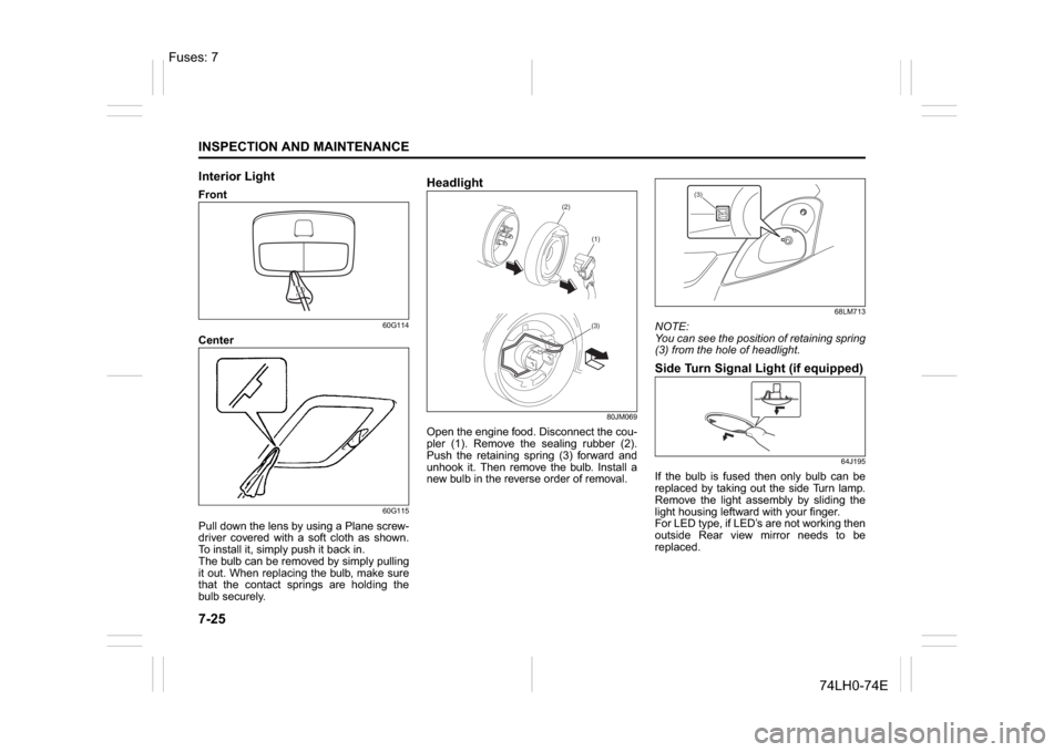
Pull down the lens by using a Plane screw-
driver covered with a soft cloth as shown.
To install it, simply push it back in.
The bulb can be removed by simply pulling
it out. When replacing the bulb, make sure
that the contact springs are holding the
bulb securely.
Headlight
80JM069
Open the engine food. Disconnect the cou-
pler (1). Remove the sealing rubber (2).
Push the retaining spring (3) forward and
unhook it. Then remove the bulb. Install a
new bulb in the reverse order of removal.
68LM713
NOTE:
You can see the position of retaining spring
(3) from the hole of headlight.Side Turn Signal Light (if equipped)
64J195
If the bulb is fused then only bulb can be
replaced by taking out the side Turn lamp.
Remove the light assembly by sliding the
light housing leftward with your finger.
For LED type, if LED’s are not working then
outside Rear view mirror needs to be
replaced.
(2)
(1)(3)
(3)
Fuses: 7
Page 217 of 336
7-26
INSPECTION AND MAINTENANCE
74LH0-74E
Other General LightsBulb holder
54G123
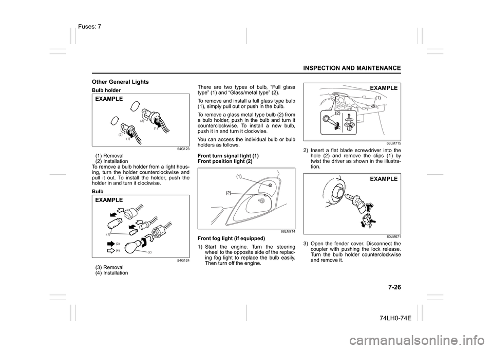
(1) Removal
(2) Installation
To remove a bulb holder from a light hous-
ing, turn the holder counterclockwise and
pull it out. To install the holder, push the
holder in and turn it clockwise.
Bulb
54G124
(3) Removal
(4) InstallationThere are two types of bulb, “Full glass
type” (1) and “Glass/metal type” (2).
To remove and install a full glass type bulb
(1), simply pull out or push in the bulb.
To remove a glass metal type bulb (2) from
a bulb holder, push in the bulb and turn it
counterclockwise. To install a new bulb,
push it in and turn it clockwise.
You can access the individual bulb or bulb
holders as follows.
Front turn signal light (1)
Front position light (2)
68LM714
Front fog light (if equipped)
1) Start the engine. Turn the steering
wheel to the opposite side of the replac-
ing fog light to replace the bulb easily.
Then turn off the engine.
68LM715
2) Insert a flat blade screwdriver into the
hole (2) and remove the clips (1) by
twist the driver as shown in the illustra-
tion.
80JM071
3) Open the fender cover. Disconnect the
coupler with pushing the lock release.
Turn the bulb holder counterclockwise
and remove it.
(1)
(1) (2)(2)
EXAMPLE
(1)
(2) (3)
(4)
EXAMPLE
EXAMPLEEXAMPLE
Fuses: 7