turn off SUZUKI SWIFT 2017 5.G Workshop Manual
[x] Cancel search | Manufacturer: SUZUKI, Model Year: 2017, Model line: SWIFT, Model: SUZUKI SWIFT 2017 5.GPages: 336, PDF Size: 6.24 MB
Page 154 of 336
5-27OTHER CONTROLS AND EQUIPMENT
74LH0-74E
6) Press or turn the TUNE FOLDER
PUSH SOUND knob (1) to select “Con-
firm”, and press the knob (1) to deter-
mine the selection.
7) Transfer contacts from the phone.
When the registration is completed, the
“Setup Phonebook” will be displayed.
NOTE:
When selecting “Go Back” the previous
menu will be displayed.
Up to 1000 numbers can be registered in
Phonebook.
Transfer of call history (Call History)
Follow the instructions below to transfer
call history of the registered phone.
1) Press the
® setup button (4).
The
® setup menu will be displayed.
2) Turn the TUNE FOLDER PUSH
SOUND knob (1) to select “Setup Tele-
phone”, and press the knob (1) to deter-
mine the selection.
3) Turn the TUNE FOLDER PUSH
SOUND knob (1) to select “Call His-
tory”, and press the knob (1) to deter-
mine the selection.
4) Turn the TUNE FOLDER PUSH
SOUND knob (1) to select “Call His-
tory?”, and press the knob (1) to deter-
mine the selection.
5) Turn the TUNE FOLDER PUSH
SOUND knob (1) to select “Confirm”,
and press the knob (1) to transfer the
call history from the phone.
NOTE:When selecting “Go Back”, the previous
menu will be displayed.
Making a call by Phonebook
Follow the instructions below to dial a num-
ber registered in Phonebook.
1) Press the Off Hook button (5).
The
® phonebook menu will be displayed.
2) Turn the TUNE FOLDER PUSH SOUND
knob (1) to select “Phonebook”, and
press the knob (1) to determine the selec-
tion.
3) Turn the TUNE FOLDER PUSH SOUND
knob (1) to select the initial of the name
you would like to make a call, and press
the knob (1) to determine the selection.
The registered numbers will be displayed
in sequence. If names have been regis-
tered together with numbers, the names
will be displayed.
4) Turn the TUNE FOLDER PUSH SOUND
knob (1) to select “Dial”, and press the
knob (1) to determine the selection.
5) Press the Off Hook bu
tton (5).
The displayed number or the number reg-
istered with the displayed name will be
dialed.
Deletion of registered data (Delete
Entry)
Follow the instructions below to delete a
number registered in Phonebook.
1) Press the
® setup button (4).
The
® setup menu will be displayed.
2) Turn the TUNE FOLDER PUSH
SOUND knob (1) to select “Setup Tele-
phone”, and press the knob (1) to deter-
mine the selection.
3) Turn the TUNE FOLDER PUSH
SOUND knob (1) to select “Setup
Phonebook”, and press the knob (1) to
determine the selection.
4) Turn the TUNE FOLDER PUSH
SOUND knob (1) to select “Delete Con-
tacts”, and press the knob (1) to deter-
mine the selection.
5) Turn the TUNE FOLDER PUSH
SOUND knob (1) to select a number to
be deleted, and press the knob (1) to
determine the selection.
6) Turn the TUNE FOLDER PUSH
SOUND knob (1) to select “Delete?”,
and press the knob (1) to determine the
selection.
7) Turn the TUNE FOLDER PUSH
SOUND knob (1) to select “Confirm”,
and press the knob (1) to complete the
deletion.
NOTE:
When selecting “Go Back”, the previous
menu will be displayed.
Page 155 of 336
5-28
OTHER CONTROLS AND EQUIPMENT
74LH0-74E
Registration in speed dial
Follow the instructions below to assign a
number to one of the Preset buttons to use
as the speed dial.
1) Press the
® setup button (4).
The
® setup menu will be displayed.
2) Turn the TUNE FOLDER PUSH
SOUND knob (1) to select “Setup Tele-
phone”, and press the knob (1) to deter-
mine the selection.
3) Turn the TUNE FOLDER PUSH
SOUND knob (1) to select “Setup
Phonebook”, and press the knob (1) to
determine the selection.
4) Turn the TUNE FOLDER PUSH
SOUND knob (1) to select “Add Speed
Dial”, and press the knob (1) to deter-
mine the selection.
5) Turn the TUNE FOLDER PUSH
SOUND knob (1) to select a number to
be assigned, and press the knob (1) to
determine the selection.
6) Turn the TUNE FOLDER PUSH
SOUND knob (1) to select “Choose
Preset”, and press the knob (1) to
determine the selection.
7) Press one of the Preset buttons (3) to
which the selected number is to be
assigned. If a number is already
assigned to the selected button, a con-
firmation message will be displayed.
Turn the TUNE FOLDER PUSH
SOUND knob (1) to select “Confirm”,
and press the knob (1) to complete the
assignment.When the assignment is completed, the
“Setup Phonebook” will be displayed.
NOTE:
When selecting “Go Back”, the previous
menu will be displayed.
One-touch call (Speed dial)
Follow the instructions below to dial the
number assigned to each of the Preset
buttons (3).
1) Press the Off Hook button (5).
The
® phonebook menu will be dis-
played.
2) Turn the TUNE FOLDER PUSH
SOUND knob (1) to select “Speed
Dials”, and press the knob (1) to deter-
mine the selection.
3) Press one of the Preset buttons (3).
When no number is assigned, “No
Entry” is displayed.
4) Press the Off Hook button (5).
The selected number will be dialed.
Deletion of speed dial (Del Speed Dial)
To delete a number assigned for the speed
dial, follow the instructions below.
1) Press the Off Hook button (5).
The® phonebook menu will be dis-
played.
2) Turn the TUNE FOLDER PUSH
SOUND knob (1) to select “Speed
Dials”, and press the knob (1) to deter-
mine the selection.
3) Press one of the Preset buttons (3) to
which the number to be deleted isassigned.
“No Entry” appears if the number is not
registered.
4) Turn the TUNE FOLDER PUSH
SOUND knob (1) to select “Delete”, and
press the knob (1) to determine the
selection.
5) Turn the TUNE FOLDER PUSH
SOUND knob (1) to select “Del Speed
Dial”, and press the knob (1) to deter-
mine the selection.
6) Turn the TUNE FOLDER PUSH
SOUND knob (1) to select “Confirm”,
and press the knob (1) to complete the
deletion.
NOTE:
When selecting “Go Back”, the previous
menu will be displayed.
Display of device data (Device Name)
Follow the instructions below to display the
BD (
® Device) address and device name.
1) Press the
® setup button (4).
The
® setup menu will be displayed.
2) Turn the TUNE FOLDER PUSH
SOUND knob (1) to select “Setup ”, and
press the knob (1) to determine the
selection.
3) Turn the TUNE FOLDER PUSH
SOUND knob (1) to select “ Info”, and
press the knob (1) to determine the
selection.
4) Turn the TUNE FOLDER PUSH
SOUND knob (1) to select “Device
Name” or “Device Address”, and press
Page 157 of 336
5-30
OTHER CONTROLS AND EQUIPMENT
74LH0-74E
key”, and press the knob (1) to deter-
mine the selection.
5) Press or turn the TUNE FOLDER
PUSH SOUND knob (1) to select “Con-
firm”.
6) Turn the TUNE FOLDER PUSH
SOUND knob (1) to select a number for
the first digit, and press the knob (1) to
determine the selection. Select and
determine numbers for the second,
third and fourth digits in order in the
same manner. When not entering up to
the eighth digit, enter blanks for the
successive digits.
7) Turn the TUNE FOLDER PUSH
SOUND knob (1) to determine the
passkey setting.
NOTE:
When selecting “Go Back”, the previous
menu will be displayed.
Deletion of phone information (Delete
Phone)
Follow the instructions below to delete the
registered information of the phone.
1) Press the
® setup button (4).
The
® setup menu will be displayed.
2) Turn the TUNE FOLDER PUSH
SOUND knob (1) to select “Setup ”, and
press the knob (1) to determine the
selection.
3) Turn the TUNE FOLDER PUSH
SOUND knob (1) to select “List Phone”,
and press the knob (1) to determine the
selection.4) Turn the TUNE FOLDER PUSH
SOUND knob (1) to select a phone to
be deleted, and press the knob (1) to
determine the selection.
5) Turn the TUNE FOLDER PUSH
SOUND knob (1) to select “Delete
Phone”, and press the knob (1) to
determine the selection.
6) Turn the TUNE FOLDER PUSH
SOUND knob (1) to select “Delete?”,
and press the knob (1) to determine the
selection.
7) Turn the TUNE FOLDER PUSH
SOUND knob (1) to select “Confirm”,
and press the knob (1) to determine the
selection.
NOTE:
When selecting “Go Back”, the previous
menu will be displayed.
BT function on/off (BT Power)
Follow the instructions below to turn on/off
the
® function.
1) Press the
® setup button (4).
The
® setup menu will be displayed.
2) Turn the TUNE FOLDER PUSH
SOUND knob (1) to select “Setup ”, and
press the knob (1) to determine the
selection.
3) Turn the TUNE FOLDER PUSH
SOUND knob (1) to select “BT Power”,
and press the knob (1) to determine the
selection.
4) Press the TUNE FOLDER PUSH
SOUND knob (1) to select “BT Power
On” or “BT Power Off ”.NOTE:
When the BT function is turned off, the
connection between this unit and the
registered phone in use will be discon-
nected.
When selecting “Go Back”, the previous
menu will be displayed.
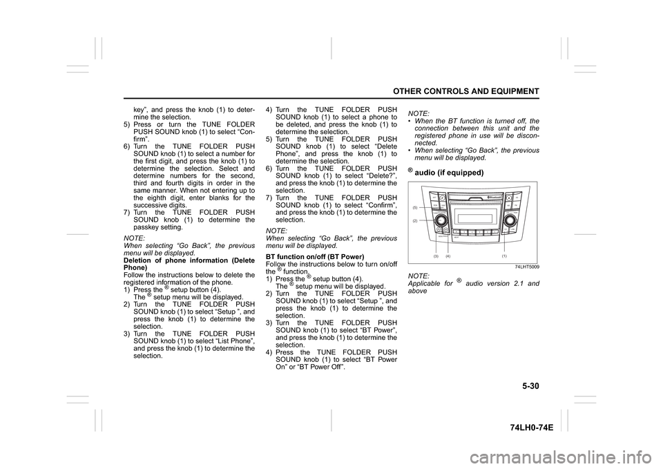
® audio (if equipped)
74LHT5009
NOTE:
Applicable for
® audio version 2.1 and
above
(2)
B
S U
CD
2
3 4 5 6
SEEK/TRACK
AS
AMFM RPT
RDM
DISP
PUSHSOUND
TUNE/FLD
VOLPWRPUSH
1
MENU
(3)
(4) (5)
Bluetooth
R(1)
Page 162 of 336
5-35OTHER CONTROLS AND EQUIPMENT
74LH0-74E
The anti-theft function is intended to dis-
courage thefts, such as that the audio sys-
tem becomes inoperable when it is
installed on other vehicles.
This function works by entering a Personal
Identification Number (PIN).
When the unit is disconnected from its
power source, such as when the audio
system is removed or the battery is discon-
nected, the unit will become inoperable
until the PIN is reentered.
Setting the Anti-Theft Function
1) Press the VOL PUSH POWER knob (1)
to power off.
2) Hold down the buttons numbered [1]
and [6] of the Preset buttons (2) and
press the VOL PUSH POWER knob (1).
“SECURITY” will be displayed.
3) Press the Up button (3) and the button
numbered [1] of the Preset buttons (2)
simultaneously.
4) Enter a 4-digit number to be registered
as PIN using the buttons numbered [1] -
[4] of the Preset buttons (2).
5) Hold down the TUNE FOLDER PUSH
SOUND knob (4) for 1 second or longer
to set the anti-theft function.
NOTE:
Take a note of the registered PIN and keep
it for the future use.Canceling the anti-theft feature
To cancel the anti-theft function, delete the
registered PIN.
1) Press the VOL PUSH POWER knob (1)
to power off.
2) Hold down the buttons numbered [1]
and [6] of the Preset buttons (2) and
press the VOL PUSH POWER knob (1).
“PIN ENTRY” will be displayed.
3) Press the Up button (3) and the button
numbered [1] of the Preset buttons (2)
simultaneously.
4) Enter a 4-digit number to be registered
as PIN using the buttons numbered [1] -
[4] of the Preset buttons (2).
5) Hold down the TUNE FOLDER PUSH
SOUND knob (4) for 1 second or longer
to delete the registered PIN. The indi-
cation “----” will be displayed and the
anti-theft function will be canceled.
NOTE:
To change your PIN, first delete your cur-
rent PIN, then set a new one.Confirming the Personal Identification
Number (PIN)
When the main power source is discon-
nected such as when the battery is
replaced, etc, it is required to enter the PIN
to make the unit operable again.
1) Set the ignition switch to the “ACC”
position.
“SECURITY” will be displayed.
2) Press the Up button (3) and the button
numbered [1] of the Preset buttons (2)
simultaneously.
3) Enter a 4-digit number to be registered
as PIN using the buttons numbered [1] -
[4] of the Preset buttons (2).
4) Hold down TUNE FOLDER PUSH
SOUND knob (4) for 1 second or lon-
ger.
When the PIN same as registered is
entered, the power of the audio system
will be turned off automatically and it
will become operable again.
NOTE:
If an incorrect PIN is entered, “ERROR”
and the total number of incorrect entry
attempts will be displayed.
If an incorrect PIN is entered 10 times,
“HELP” will be displayed and the audio
system will become inoperable.
Page 176 of 336
5-49OTHER CONTROLS AND EQUIPMENT
74LH0-74E
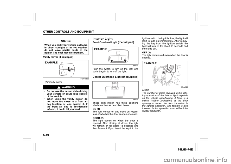
Vanity mirror (if equipped)
74LHT0532
(2) Vanity mirror
Interior Light Front Overhead Light
(if equipped)
64J104
Push the switch to turn on the light and
push it again to turn off the light.Center Overhead Light (if equipped)
64J104
These light switch has three positions
which function as described below:
ON (1)
The light comes on and stays on regard-
less of whether the door is open or closed.
DOOR (2)
The light comes on when the door is
opened. After closing all doors, the light
will remain on for about 15 seconds and
then fade out. If you insert the key into theignition switch during this time, the light will
start to fade out immediately. After remov-
ing the key from the ignition switch, the
light will turn on for about 15 seconds and
then fade out.
OFF (3)
The light remains off even when the door is
opened.
68LM529
NOTE:
The number of doors involved in the light-
ing operation of the interior light depends
on the vehicle specification. If there is a
switch (rubber projection) at the door
opening as shown, the door is involved in
the lighting operation. The tailgate is also
involved in this operation even without the
rubber projection.
NOTICE
When you park your vehicle outdoors
in direct sunlight or in hot weather,
do not leave plastic cards in the
holder. The heat may distort them.
WA R N I N G
Do not use the mirror while driving
your vehicle or could lose control
of the vehicle.
When using the vanity mirror, do
not move too close to a front air
bag location or lean against it. If
the front air bag is accidentally
inflated, it could hit you hard.
(2)
EXAMPLE
EXAMPLE
(1)(2)(3)
EXAMPLE
Page 187 of 336
6-4
VEHICLE LOADING AND TOWING
74LH0-74E
60A186
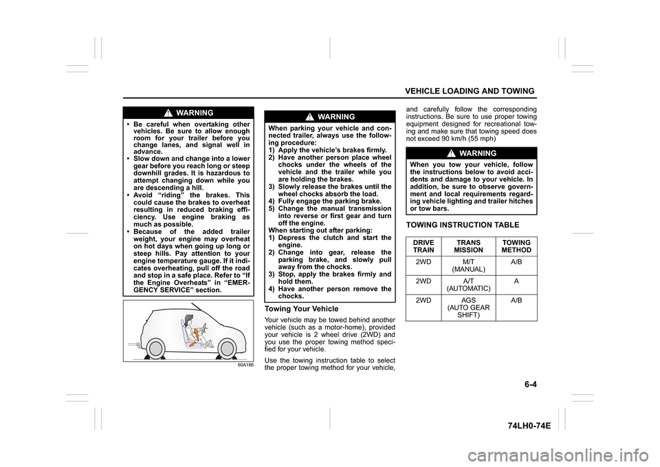
Towing Your VehicleYour vehicle may be towed behind another
vehicle (such as a motor-home), provided
your vehicle is 2 wheel drive (2WD) and
you use the proper towing method speci-
fied for your vehicle.
Use the towing instruction table to select
the proper towing method for your vehicle,and carefully follow the corresponding
instructions. Be sure to use proper towing
equipment designed for recreational tow-
ing and make sure that towing speed does
not exceed 90 km/h (55 mph)
TOWING INSTRUCTION TABLE
WA R N I N G
Be careful when overtaking other
vehicles. Be sure to allow enough
room for your trailer before you
change lanes, and signal well in
advance. Slow down and change into a lower
gear before you reach long or steep
downhill grades. It is hazardous to
attempt changing down while you
are descending a hill.
Avoid “riding” the brakes. This
could cause the brakes to overheat
resulting in reduced braking effi-
ciency. Use engine braking as
much as possible.
Because of the added trailer
weight, your engine may overheat
on hot days when going up long or
steep hills. Pay attention to your
engine temperature gauge. If it indi-
cates overheating, pull off the road
and stop in a safe place. Refer to “If
the Engine Overheats” in “EMER-
GENCY SERVICE” section.
WA R N I N G
When parking your vehicle and con-
nected trailer, always use the follow-
ing procedure:
1) Apply the vehicle’s brakes firmly.
2) Have another person place wheel
chocks under the wheels of the
vehicle and the trailer while you
are holding the brakes.
3) Slowly release the brakes until the
wheel chocks absorb the load.
4) Fully engage the parking brake.
5) Change the manual transmission
into reverse or first gear and turn
off the engine.
When starting out after parking:
1) Depress the clutch and start the
engine.
2) Change into gear, release the
parking brake, and slowly pull
away from the chocks.
3) Stop, apply the brakes firmly and
hold them.
4) Have another person remove the
chocks.
WA R N I N G
When you tow your vehicle, follow
the instructions below to avoid acci-
dents and damage to your vehicle. In
addition, be sure to observe govern-
ment and local requirements regard-
ing vehicle lighting and trailer hitches
or tow bars.
DRIVE
TRAINTRANS
MISSIONTOWING
METHOD
2WD M/T
(MANUAL)A/B
2WD A/T
(AUTOMATIC)A
2WD AGS
(AUTO GEAR
SHIFT)A/B
Page 200 of 336
7-9INSPECTION AND MAINTENANCE
74LH0-74E
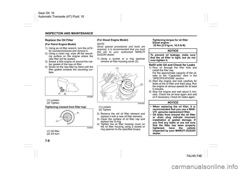
Replace the Oil Filter(For Petrol Engine Model)
1) Using an oil filter wrench, turn the oil fil-
ter counterclockwise and remove it.
2) Using a clean rag, wipe off the mount-
ing surface on the engine where the
new filter will be seated.
3) Smear a little engine oil around the rub-
ber gasket of the new oil filter.
4) Screw on the new filter by hand until the
filter gasket contacts the mounting sur-
face.
54G092
(1) Loosen
(2) Tighten
Tightening (viewed from filter top)
54G093
(1) Oil filter
(2) 3/4 turn(For Diesel Engine Model)
NOTE:
Since special procedures and tools are
required, it is recommended that you trust
this job to your authorized MARUTI
SUZUKI dealer.
1) Using a socket or a ring spanner
remove oil filter housing cover (3).
61M7001
(1) Loosen
(2) Tighten
2) Remove the old oil filter element and
replace it with a new oil filter element.
3) Clean the surface of oil filter cap and
replace the O-ring.
4) Tighten the oil filter housing cover on
the oil filter housing using a socket or
ring spanner to the specified torque.Tightening torque for oil filter
Diesel engine :
25 Nm (2.5 kg-m, 18.5 lb-ft)
Refill with Oil and Check for Leaks1) Pour oil through the filler hole and
install the filler cap.
For the approximate capacity of the oil,
refer to the “Capacities” item in the
“SPECIFICATIONS” section.
2) Start the engine and look carefully for
leaks at the oil filter and drain plug. Run
the engine at various speeds for at least
5 minutes.
3) Stop the engine and wait about 5 min-
utes. Check the oil level again and add
oil if necessary. Check for leaks again.
(1)
(3)
(2)
NOTICE
To prevent oil leakage, make sure
that the oil filter is tight, but do not
over-tighten it.
NOTICE
When replacing the oil filter, it is
recommended that you use a MAR-
UTI genuine replacement filter.
Oil leaks from around the oil filter
or drain plug indicate incorrect
installation or gasket damage. If
you find any leaks or are not sure
that the filter has been properly
tightened, have the vehicle
inspected by your MARUTI SUZUKI
dealer.
Gear Oil: 10
Automatic Transaxle (AT) Fluid: 10
Page 215 of 336
7-24
INSPECTION AND MAINTENANCE
74LH0-74E
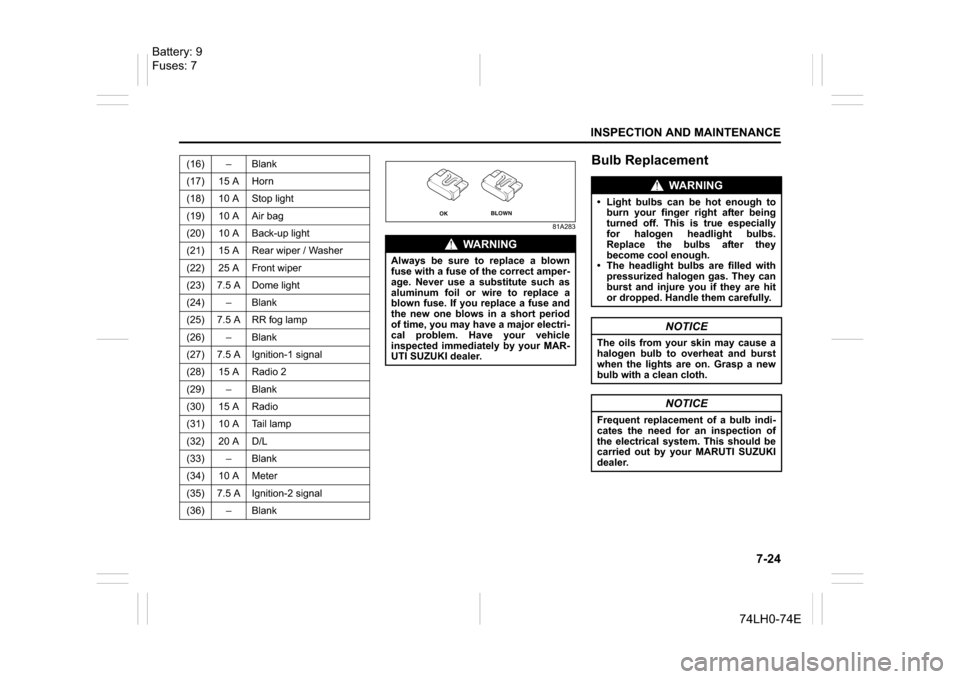
81A283
Bulb Replacement
(16) – Blank
(17) 15 A Horn
(18) 10 A Stop light
(19) 10 A Air bag
(20) 10 A Back-up light
(21) 15 A Rear wiper / Washer
(22) 25 A Front wiper
(23) 7.5 A Dome light
(24) – Blank
(25) 7.5 A RR fog lamp
(26) – Blank
(27) 7.5 A Ignition-1 signal
(28) 15 A Radio 2
(29) – Blank
(30) 15 A Radio
(31) 10 A Tail lamp
(32) 20 A D/L
(33) – Blank
(34) 10 A Meter
(35) 7.5 A Ignition-2 signal
(36) – Blank
WA R N I N G
Always be sure to replace a blown
fuse with a fuse of the correct amper-
age. Never use a substitute such as
aluminum foil or wire to replace a
blown fuse. If you replace a fuse and
the new one blows in a short period
of time, you may have a major electri-
cal problem. Have your vehicle
inspected immediately by your MAR-
UTI SUZUKI dealer.
OK
BLOWN
WA R N I N G
Light bulbs can be hot enough to
burn your finger right after being
turned off. This is true especially
for halogen headlight bulbs.
Replace the bulbs after they
become cool enough.
The headlight bulbs are filled with
pressurized halogen gas. They can
burst and injure you if they are hit
or dropped. Handle them carefully.
NOTICE
The oils from your skin may cause a
halogen bulb to overheat and burst
when the lights are on. Grasp a new
bulb with a clean cloth.
NOTICE
Frequent replacement of a bulb indi-
cates the need for an inspection of
the electrical system. This should be
carried out by your MARUTI SUZUKI
dealer.
Battery: 9
Fuses: 7
Page 217 of 336
7-26
INSPECTION AND MAINTENANCE
74LH0-74E
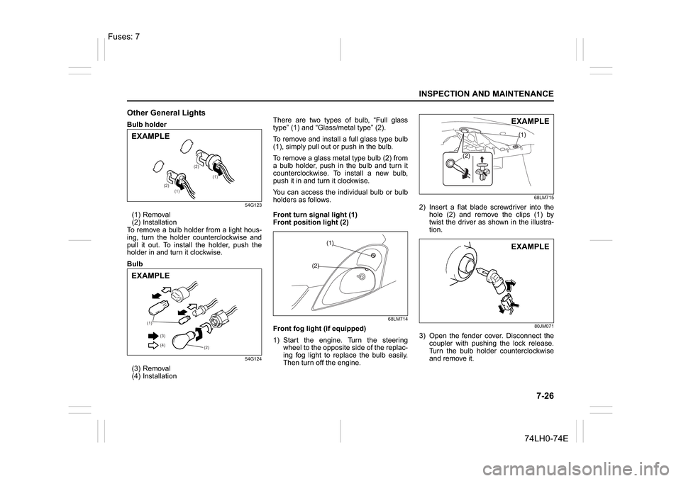
Other General LightsBulb holder
54G123
(1) Removal
(2) Installation
To remove a bulb holder from a light hous-
ing, turn the holder counterclockwise and
pull it out. To install the holder, push the
holder in and turn it clockwise.
Bulb
54G124
(3) Removal
(4) InstallationThere are two types of bulb, “Full glass
type” (1) and “Glass/metal type” (2).
To remove and install a full glass type bulb
(1), simply pull out or push in the bulb.
To remove a glass metal type bulb (2) from
a bulb holder, push in the bulb and turn it
counterclockwise. To install a new bulb,
push it in and turn it clockwise.
You can access the individual bulb or bulb
holders as follows.
Front turn signal light (1)
Front position light (2)
68LM714
Front fog light (if equipped)
1) Start the engine. Turn the steering
wheel to the opposite side of the replac-
ing fog light to replace the bulb easily.
Then turn off the engine.
68LM715
2) Insert a flat blade screwdriver into the
hole (2) and remove the clips (1) by
twist the driver as shown in the illustra-
tion.
80JM071
3) Open the fender cover. Disconnect the
coupler with pushing the lock release.
Turn the bulb holder counterclockwise
and remove it.
(1)
(1) (2)(2)
EXAMPLE
(1)
(2) (3)
(4)
EXAMPLE
EXAMPLEEXAMPLE
Fuses: 7
Page 228 of 336
8-5EMERGENCY SERVICE
74LH0-74E
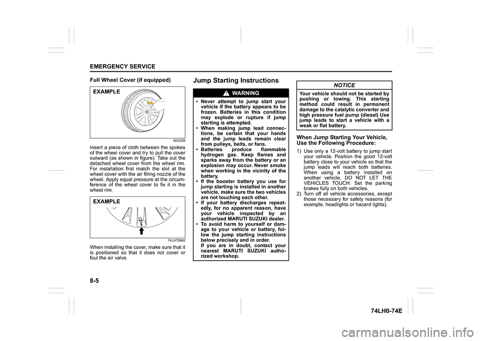
Full Wheel Cover (if equipped)
60G309
Insert a piece of cloth between the spokes
of the wheel cover and try to pull the cover
outward (as shown in figure). Take out the
detached wheel cover from the wheel rim.
For installation first match the slot at the
wheel cover with the air filling nozzle of the
wheel. Apply equal pressure at the circum-
ference of the wheel cover to fix it in the
wheel rim.
74LHT0860
When installing the cover, make sure that it
is positioned so that it does not cover or
foul the air valve.
Jump Starting Instructions
When Jump Starting Your Vehicle,
Use the Following Procedure:1) Use only a 12-volt battery to jump start
your vehicle. Position the good 12-volt
battery close to your vehicle so that the
jump leads will reach both batteries.
When using a battery installed on
another vehicle, DO NOT LET THE
VEHICLES TOUCH. Set the parking
brakes fully on both vehicles.
2) Turn off all vehicle accessories, except
those necessary for safety reasons (for
example, headlights or hazard lights).
EXAMPLEEXAMPLE
WA R N I N G
Never attempt to jump start your
vehicle if the battery appears to be
frozen. Batteries in this condition
may explode or rupture if jump
starting is attempted.
When making jump lead connec-
tions, be certain that your hands
and the jump leads remain clear
from pulleys, belts, or fans.
Batteries produce flammable
hydrogen gas. Keep flames and
sparks away from the battery or an
explosion may occur. Never smoke
when working in the vicinity of the
battery.
If the booster battery you use for
jump starting is installed in another
vehicle, make sure the two vehicles
are not touching each other.
If your battery discharges repeat-
edly, for no apparent reason, have
your vehicle inspected by an
authorized MARUTI SUZUKI dealer.
To avoid harm to yourself or dam-
age to your vehicle or battery, fol-
low the jump starting instructions
below precisely and in order.
If you are in doubt, contact your
nearest MARUTI SUZUKI autho-
rized workshop.
NOTICE
Your vehicle should not be started by
pushing or towing. This starting
method could result in permanent
damage to the catalytic converter and
high pressure fuel pump (diesel) Use
jump leads to start a vehicle with a
weak or flat battery.