cylinder SUZUKI SX4 2006 1.G Service Workshop Manual
[x] Cancel search | Manufacturer: SUZUKI, Model Year: 2006, Model line: SX4, Model: SUZUKI SX4 2006 1.GPages: 1556, PDF Size: 37.31 MB
Page 468 of 1556
Downloaded from www.Manualslib.com manuals search engine 2C-9 Rear Suspension:
Installation
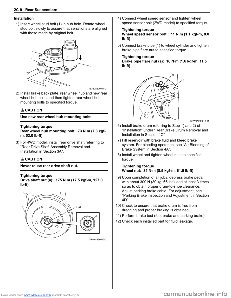
1) Insert wheel stud bolt (1) in hub hole. Rotate wheel
stud bolt slowly to assure that serrations are aligned
with those made by original bolt.
2) Install brake back plate, rear wheel hub and new rear
wheel hub bolts and then tighten rear wheel hub
mounting bolts to specified torque.
CAUTION!
Use new rear wheel hub mounting bolts.
Tightening torque
Rear wheel hub mounting bolt: 73 N·m (7.3 kgf-
m, 53.0 lb-ft)
3) For 4WD model, install rear drive shaft referring to
“Rear Drive Shaft Assembly Removal and
Installation in Section 3A”.
CAUTION!
Never reuse rear drive shaft nut.
Tightening torque
Drive shaft nut (a): 175 N·m (17.5 kgf-m, 127.0
lb-ft)4) Connect wheel speed sensor and tighten wheel
speed sensor bolt (2WD model) to specified torque.
Tightening torque
Wheel speed sensor bolt : 11 N·m (1.1 kgf-m, 8.0
lb-ft)
5) Connect brake pipe (1) to wheel cylinder and tighten
brake pipe flare nut to specified torque.
Tightening torque
Brake pipe flare nut (a): 16 N·m (1.6 kgf-m, 11.5
lb-ft)
6) Install brake drum referring to Step 1) and 2) of
“Installation” under “Rear Brake Drum Removal and
Installation in Section 4C”.
7) Fill reservoir with brake fluid and bleed brake
system. For bleeding operation, see “Air Bleeding of
Brake System in Section 4A”.
8) Install wheel and tighten wheel nuts to specified
torque.
Tightening torque
Wheel nut: 85 N·m (8.5 kgf-m, 61.5 lb-ft)
9) Upon completion of all jobs, depress brake pedal
with about 300 N (30 kg, 66 lbs) load at least 3 times
so as to obtain proper drum-to-shoe clearance.
Adjust parking brake cable. For adjustment, see
“Parking Brake Inspection and Adjustment in Section
4D”.
10) Check to ensure that brake drum is free from
dragging and proper braking is obtained.
11) Perform brake test (foot brake and parking brake).
12) Check each installed part for fluid leakage.
1
I5JB0A220017-01
1,(a)
1
I7RW01230012-01
(a)
1
I5RW0A230018-01
Page 569 of 1556
Downloaded from www.Manualslib.com manuals search engine Table of Contents 4- i
4
Section 4
CONTENTS
Brakes
Precautions ................................................. 4-1
Precautions............................................................. 4-1
Precautions for Brakes .......................................... 4-1
Brake Control System and Diagnosis ... 4A-1
Precautions........................................................... 4A-1
Precautions on Brake .......................................... 4A-1
General Description ............................................. 4A-1
Brakes Construction ............................................ 4A-1
Brake Pedal Foot Protection System
Construction (If Equipped) ................................ 4A-2
Front Brake Hose / Pipe Construction................. 4A-3
Rear Brake Hose / Pipe Construction ................. 4A-4
Diagnostic Information and Procedures ............ 4A-4
Brakes Diagnosis Note ....................................... 4A-4
Brakes Symptom Diagnosis ................................ 4A-5
Repair Instructions .............................................. 4A-7
Brake Pedal Components ................................... 4A-7
Brake Pedal Free Height Inspection ................... 4A-7
Brake Pedal Play Inspection ............................... 4A-7
Excessive Pedal Travel Inspection ..................... 4A-7
Brake Fluid Level Inspection ............................... 4A-8
Brake Light Switch Adjustment ........................... 4A-8
Air Bleeding of Brake System ............................. 4A-8
Front Brake Hose / Pipe Removal and
Installation ......................................................... 4A-9
Rear Brake Hose / Pipe Removal and
Installation ....................................................... 4A-10
Brake Hose and Pipe Inspection ....................... 4A-10
Master Cylinder and Brake Booster
Components.................................................... 4A-11
Master Cylinder Reservoir Removal and
Installation ....................................................... 4A-11
Master Cylinder Removal and Installation......... 4A-12
Master Cylinder Inspection ............................... 4A-13
Booster Operation Inspection ........................... 4A-14
Brake Booster Removal and Installation ........... 4A-15
Brake Booster Inspection .................................. 4A-15
Booster Push Clevis Rod Adjustment ............... 4A-16
Specifications..................................................... 4A-16
Tightening Torque Specifications ...................... 4A-16
Special Tools and Equipment ........................... 4A-16
Recommended Service Material ....................... 4A-16
Special Tool ...................................................... 4A-16
Front Brakes ............................................ 4B-1
Repair Instructions ..............................................4B-1
Front Disc Brake Components ............................ 4B-1
Front Disc Brake Pad On-Vehicle Inspection ...... 4B-2
Front Disc Brake Pad Removal and
Installation ......................................................... 4B-2
Front Disc Brake Pad Inspection......................... 4B-3
Front Disc Brake Caliper Removal and
Installation ......................................................... 4B-3
Front Disc Brake Caliper Disassembly and
Assembly........................................................... 4B-4
Front Disc Brake Caliper Inspection.................... 4B-6
Front Brake Disc Removal and Installation ......... 4B-6
Front Brake Disc Inspection ................................ 4B-7
Specifications .......................................................4B-8
Tightening Torque Specifications ........................ 4B-8
Special Tools and Equipment .............................4B-8
Recommended Service Material ......................... 4B-8
Special Tool ........................................................ 4B-8
Rear Brakes.............................................. 4C-1
Repair Instructions ..............................................4C-1
Rear Drum Brake Components ...........................4C-1
Rear Brake Drum Removal and Installation ........4C-2
Rear Brake Drum and Shoe Inspection ..............4C-2
Rear Brake Shoe On-Vehicle Inspection ............4C-3
Rear Brake Shoe Removal and Installation ........4C-3
Rear Brake Shoe Inspection ...............................4C-4
Wheel Cylinder Removal and Installation ...........4C-4
Wheel Cylinder Inspection ..................................4C-5
Brake Back Plate Removal and Installation ........4C-5
Specifications .......................................................4C-6
Tightening Torque Specifications ........................4C-6
Special Tools and Equipment .............................4C-6
Recommended Service Material .........................4C-6
Parking Brake .......................................... 4D-1
General Description .............................................4D-1
Parking Brake Cable Construction ......................4D-1
Repair Instructions ..............................................4D-2
Parking Brake Inspection and Adjustment ..........4D-2
Parking Brake Cable Removal and
Installation .........................................................4D-2
Parking Brake Lever Removal and Installation ....4D-3
Page 572 of 1556
Downloaded from www.Manualslib.com manuals search engine 4A-1 Brake Control System and Diagnosis:
Brakes
Brake Control System and Diagnosis
Precautions
Precautions on BrakeS6RW0D4100001
Air Bag Warning
Refer to“Air Bag Warning in Section 00”.
Brakes Diagnosis Note
Refer to “Brakes Diagnosis Note”.
General Description
Brakes ConstructionS6RW0D4101001
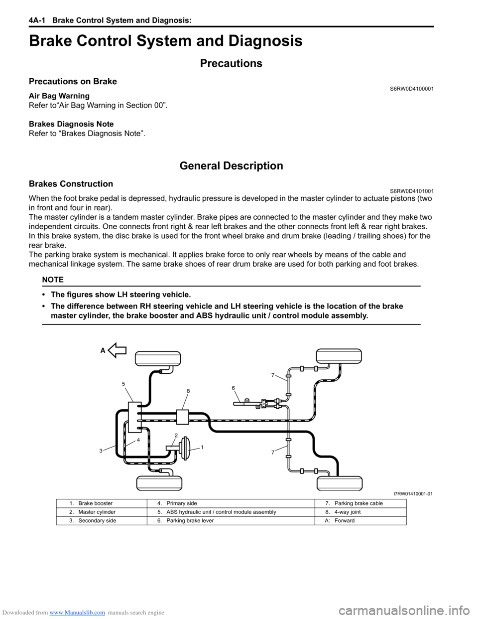
When the foot brake pedal is depressed, hydraulic pressure is developed in the master cylinder to actuate pistons (two
in front and four in rear).
The master cylinder is a tandem master cylinder. Brake pipes are connected to the master cylinder and they make two
independent circuits. One connects front right & rear left brakes and the other connects front left & rear right brakes.
In this brake system, the disc brake is used for the front wheel brake and drum brake (leading / trailing shoes) for the
rear brake.
The parking brake system is mechanical. It applies brake force to only rear wheels by means of the cable and
mechanical linkage system. The same brake shoes of rear drum brake are used for both parking and foot brakes.
NOTE
• The figures show LH steering vehicle.
• The difference between RH steering vehicle and LH steering vehicle is the location of the brake
master cylinder, the brake booster and ABS hydraulic unit / control module assembly.
A
421
37
7
658
I7RW01410001-01
1. Brake booster 4. Primary side 7. Parking brake cable
2. Master cylinder 5. ABS hydraulic unit / control module assembly 8. 4-way joint
3. Secondary side 6. Parking brake lever A: Forward
Page 574 of 1556
![SUZUKI SX4 2006 1.G Service Workshop Manual Downloaded from www.Manualslib.com manuals search engine 4A-3 Brake Control System and Diagnosis:
Front Brake Hose / Pipe ConstructionS6RW0D4101002
I6RW0C410002-01
[A]: LHD 4. From ABS hydraulic unit SUZUKI SX4 2006 1.G Service Workshop Manual Downloaded from www.Manualslib.com manuals search engine 4A-3 Brake Control System and Diagnosis:
Front Brake Hose / Pipe ConstructionS6RW0D4101002
I6RW0C410002-01
[A]: LHD 4. From ABS hydraulic unit](/img/20/7612/w960_7612-573.png)
Downloaded from www.Manualslib.com manuals search engine 4A-3 Brake Control System and Diagnosis:
Front Brake Hose / Pipe ConstructionS6RW0D4101002
I6RW0C410002-01
[A]: LHD 4. From ABS hydraulic unit to left front brake 9. Master cylinder fixing nut
[B]: RHD 5. ABS hydraulic unit / control module assembly : 18 N⋅m (1.8 kgf-m, 13.0 lb-ft)
1. From master cylinder primary to ABS
hydraulic unit6. Master cylinder : 16 N⋅m (1.6 kgf-m, 12.0 lb-ft)
2. From master cylinder secondary to ABS
hydraulic unit7. From ABS hydraulic unit to left rear brake : 11 N⋅m (1.1 kgf-m, 8.0 lb-ft)
3. From ABS hydraulic unit to right front brake 8. From ABS hydraulic unit to right rear brake : 9 N⋅m (0.9 kgf-m, 6.5 lb-ft)
Page 575 of 1556
Downloaded from www.Manualslib.com manuals search engine Brake Control System and Diagnosis: 4A-4
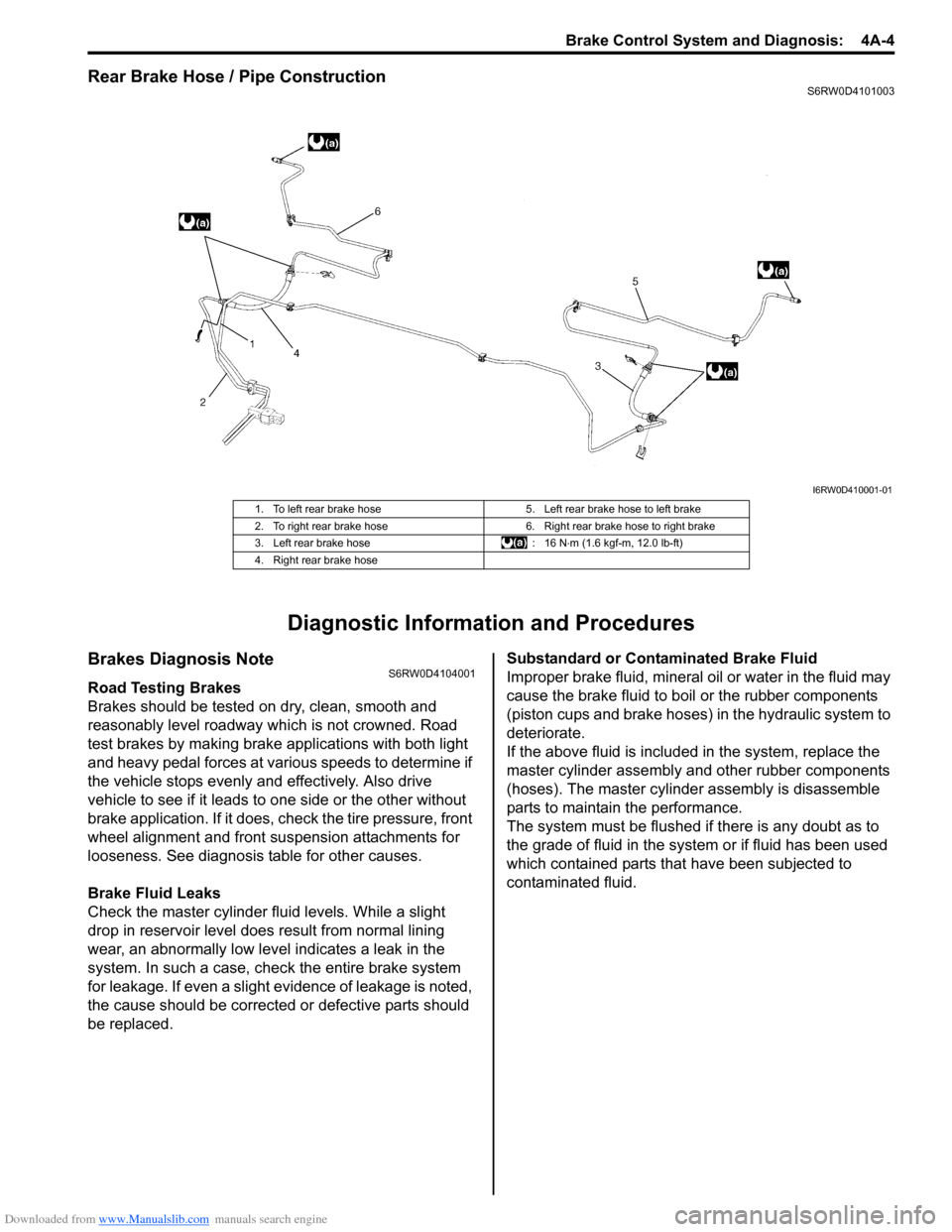
Rear Brake Hose / Pipe ConstructionS6RW0D4101003
Diagnostic Information and Procedures
Brakes Diagnosis NoteS6RW0D4104001
Road Testing Brakes
Brakes should be tested on dry, clean, smooth and
reasonably level roadway which is not crowned. Road
test brakes by making brake applications with both light
and heavy pedal forces at various speeds to determine if
the vehicle stops evenly and effectively. Also drive
vehicle to see if it leads to one side or the other without
brake application. If it does, check the tire pressure, front
wheel alignment and front suspension attachments for
looseness. See diagnosis table for other causes.
Brake Fluid Leaks
Check the master cylinder fluid levels. While a slight
drop in reservoir level does result from normal lining
wear, an abnormally low level indicates a leak in the
system. In such a case, check the entire brake system
for leakage. If even a slight evidence of leakage is noted,
the cause should be corrected or defective parts should
be replaced.Substandard or Contaminated Brake Fluid
Improper brake fluid, mineral oil or water in the fluid may
cause the brake fluid to boil or the rubber components
(piston cups and brake hoses) in the hydraulic system to
deteriorate.
If the above fluid is included in the system, replace the
master cylinder assembly and other rubber components
(hoses). The master cylinder assembly is disassemble
parts to maintain the performance.
The system must be flushed if there is any doubt as to
the grade of fluid in the system or if fluid has been used
which contained parts that have been subjected to
contaminated fluid.
I6RW0D410001-01
1. To left rear brake hose 5. Left rear brake hose to left brake
2. To right rear brake hose 6. Right rear brake hose to right brake
3. Left rear brake hose : 16 N⋅m (1.6 kgf-m, 12.0 lb-ft)
4. Right rear brake hose
Page 576 of 1556
Downloaded from www.Manualslib.com manuals search engine 4A-5 Brake Control System and Diagnosis:
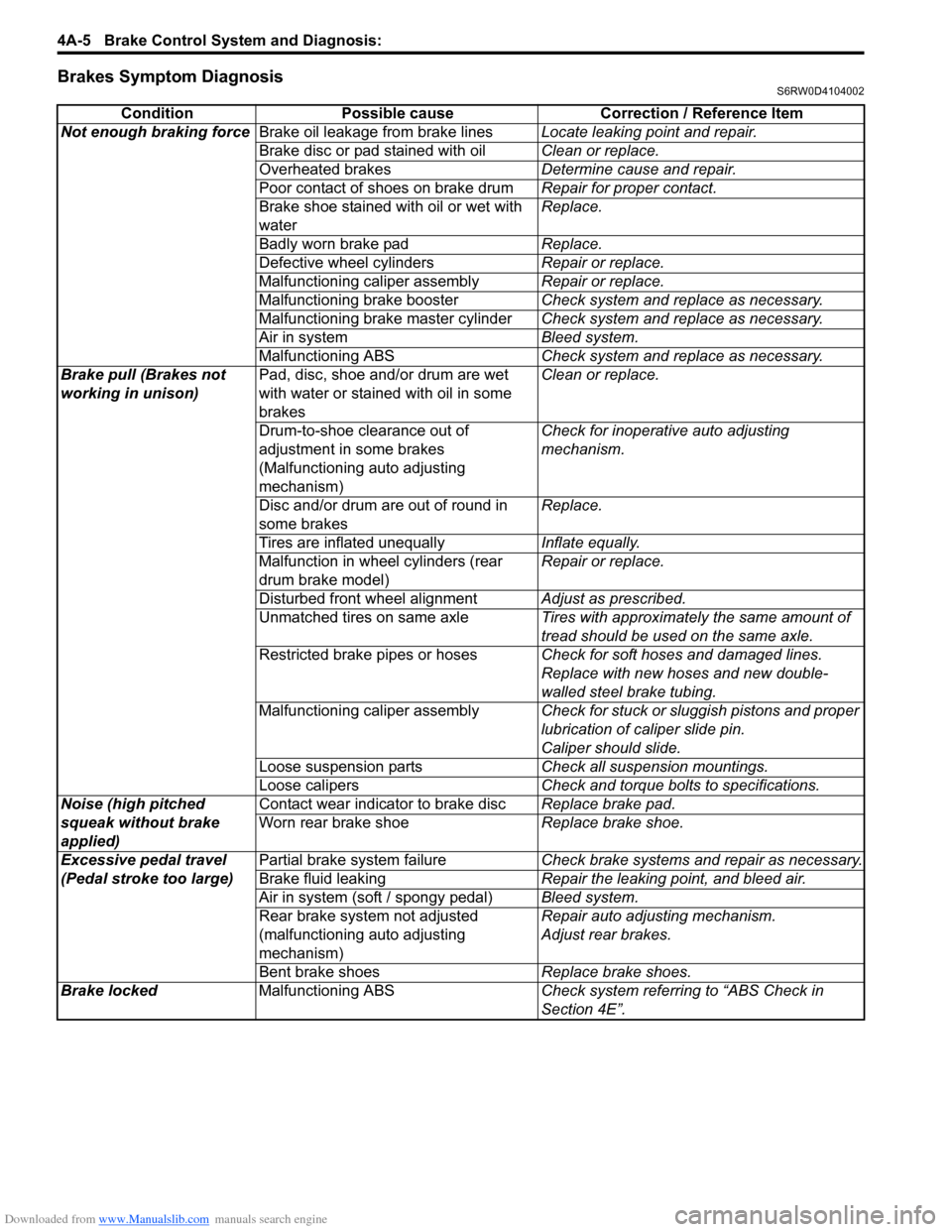
Brakes Symptom DiagnosisS6RW0D4104002
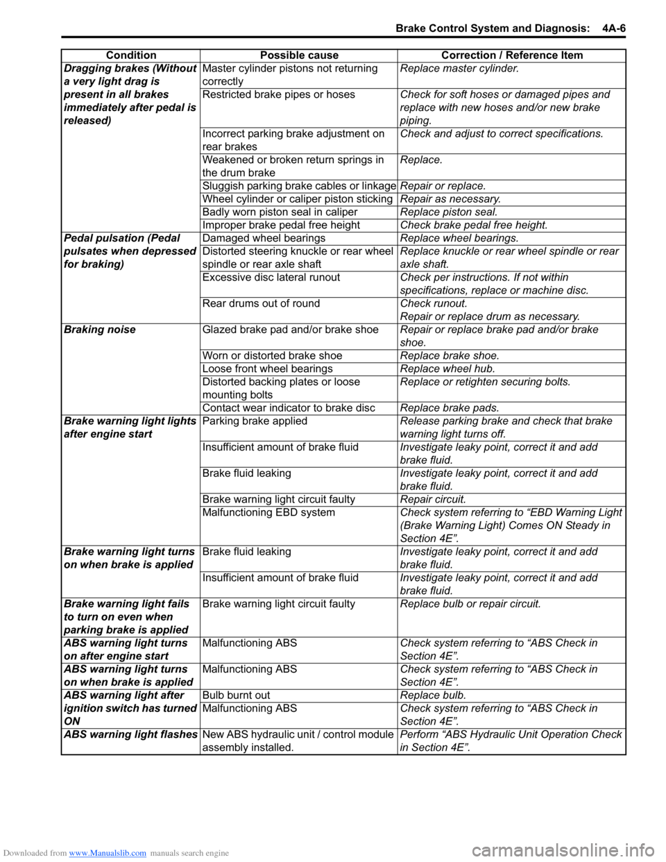
Condition Possible cause Correction / Reference Item
Not enough braking forceBrake oil leakage from brake linesLocate leaking point and repair.
Brake disc or pad stained with oilClean or replace.
Overheated brakesDetermine cause and repair.
Poor contact of shoes on brake drumRepair for proper contact.
Brake shoe stained with oil or wet with
waterReplace.
Badly worn brake padReplace.
Defective wheel cylindersRepair or replace.
Malfunctioning caliper assemblyRepair or replace.
Malfunctioning brake boosterCheck system and replace as necessary.
Malfunctioning brake master cylinderCheck system and replace as necessary.
Air in systemBleed system.
Malfunctioning ABSCheck system and replace as necessary.
Brake pull (Brakes not
working in unison)Pad, disc, shoe and/or drum are wet
with water or stained with oil in some
brakesClean or replace.
Drum-to-shoe clearance out of
adjustment in some brakes
(Malfunctioning auto adjusting
mechanism) Check for inoperative auto adjusting
mechanism.
Disc and/or drum are out of round in
some brakesReplace.
Tires are inflated unequallyInflate equally.
Malfunction in wheel cylinders (rear
drum brake model)Repair or replace.
Disturbed front wheel alignmentAdjust as prescribed.
Unmatched tires on same axleTires with approximately the same amount of
tread should be used on the same axle.
Restricted brake pipes or hosesCheck for soft hoses and damaged lines.
Replace with new hoses and new double-
walled steel brake tubing.
Malfunctioning caliper assemblyCheck for stuck or sluggish pistons and proper
lubrication of caliper slide pin.
Caliper should slide.
Loose suspension partsCheck all suspension mountings.
Loose calipersCheck and torque bolts to specifications.
Noise (high pitched
squeak without brake
applied)Contact wear indicator to brake discReplace brake pad.
Worn rear brake shoeReplace brake shoe.
Excessive pedal travel
(Pedal stroke too large)Partial brake system failureCheck brake systems and repair as necessary.
Brake fluid leakingRepair the leaking point, and bleed air.
Air in system (soft / spongy pedal)Bleed system.
Rear brake system not adjusted
(malfunctioning auto adjusting
mechanism)Repair auto adjusting mechanism.
Adjust rear brakes.
Bent brake shoesReplace brake shoes.
Brake locked Malfunctioning ABSCheck system referring to “ABS Check in
Section 4E”.
Page 577 of 1556
Downloaded from www.Manualslib.com manuals search engine Brake Control System and Diagnosis: 4A-6
Dragging brakes (Without
a very light drag is
present in all brakes
immediately after pedal is
released)Master cylinder pistons not returning
correctlyReplace master cylinder.
Restricted brake pipes or hosesCheck for soft hoses or damaged pipes and
replace with new hoses and/or new brake
piping.
Incorrect parking brake adjustment on
rear brakesCheck and adjust to correct specifications.
Weakened or broken return springs in
the drum brakeReplace.
Sluggish parking brake cables or linkageRepair or replace.
Wheel cylinder or caliper piston stickingRepair as necessary.
Badly worn piston seal in caliperReplace piston seal.
Improper brake pedal free heightCheck brake pedal free height.
Pedal pulsation (Pedal
pulsates when depressed
for braking)Damaged wheel bearingsReplace wheel bearings.
Distorted steering knuckle or rear wheel
spindle or rear axle shaftReplace knuckle or rear wheel spindle or rear
axle shaft.
Excessive disc lateral runoutCheck per instructions. If not within
specifications, replace or machine disc.
Rear drums out of roundCheck runout.
Repair or replace drum as necessary.
Braking noiseGlazed brake pad and/or brake shoeRepair or replace brake pad and/or brake
shoe.
Worn or distorted brake shoeReplace brake shoe.
Loose front wheel bearingsReplace wheel hub.
Distorted backing plates or loose
mounting boltsReplace or retighten securing bolts.
Contact wear indicator to brake discReplace brake pads.
Brake warning light lights
after engine startParking brake appliedRelease parking brake and check that brake
warning light turns off.
Insufficient amount of brake fluidInvestigate leaky point, correct it and add
brake fluid.
Brake fluid leakingInvestigate leaky point, correct it and add
brake fluid.
Brake warning light circuit faultyRepair circuit.
Malfunctioning EBD systemCheck system referring to “EBD Warning Light
(Brake Warning Light) Comes ON Steady in
Section 4E”.
Brake warning light turns
on when brake is appliedBrake fluid leakingInvestigate leaky point, correct it and add
brake fluid.
Insufficient amount of brake fluidInvestigate leaky point, correct it and add
brake fluid.
Brake warning light fails
to turn on even when
parking brake is appliedBrake warning light circuit faultyReplace bulb or repair circuit.
ABS warning light turns
on after engine startMalfunctioning ABSCheck system referring to “ABS Check in
Section 4E”.
ABS warning light turns
on when brake is appliedMalfunctioning ABSCheck system referring to “ABS Check in
Section 4E”.
ABS warning light after
ignition switch has turned
ON Bulb burnt outReplace bulb.
Malfunctioning ABSCheck system referring to “ABS Check in
Section 4E”.
ABS warning light flashesNew ABS hydraulic unit / control module
assembly installed.Perform “ABS Hydraulic Unit Operation Check
in Section 4E”. Condition Possible cause Correction / Reference Item
Page 579 of 1556
Downloaded from www.Manualslib.com manuals search engine Brake Control System and Diagnosis: 4A-8
Brake Fluid Level InspectionS6RW0D4106004
CAUTION!
Do not use shock absorber fluid or any other
fluid which contains mineral oil. Do not use a
container which has been used for mineral oil
or a container which is wet from water.
Mineral oil will cause swelling and distortion
of rubber parts in hydraulic brake system and
water mixed into brake fluid will lower fluid
boiling point. Keep all fluid containers
capped to prevent contamination.
NOTE
Be sure to use particular brake fluid either as
indicated on reservoir cap of that vehicle or
recommended in owner’s manual which
comes along with that vehicle. Use of any
other fluid is strictly prohibited.
Fluid level should be between MIN and MAX
lines marked on reservoir.
When brake warning light lights sometimes
during driving, replenish fluid to MAX level.
When fluid decreases quickly, inspect brake
system for leakage. Correct leaky points and
then refill to specified level.
1) Check master cylinder, reservoir and reservoir hose
(if equipped) for crack, damage and brake fluid
leakage. If any faulty condition exists, correct or
replace.
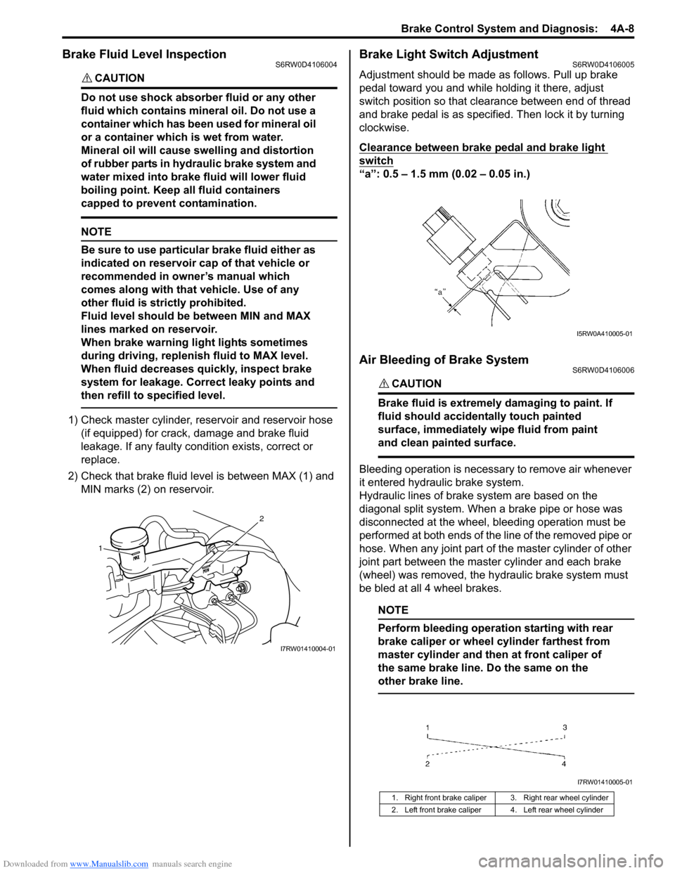
2) Check that brake fluid level is between MAX (1) and
MIN marks (2) on reservoir.
Brake Light Switch AdjustmentS6RW0D4106005
Adjustment should be made as follows. Pull up brake
pedal toward you and while holding it there, adjust
switch position so that clearance between end of thread
and brake pedal is as specified. Then lock it by turning
clockwise.
Clearance between brake pedal and brake light
switch
“a”: 0.5 – 1.5 mm (0.02 – 0.05 in.)
Air Bleeding of Brake SystemS6RW0D4106006
CAUTION!
Brake fluid is extremely damaging to paint. If
fluid should accidentally touch painted
surface, immediately wipe fluid from paint
and clean painted surface.
Bleeding operation is necessary to remove air whenever
it entered hydraulic brake system.
Hydraulic lines of brake system are based on the
diagonal split system. When a brake pipe or hose was
disconnected at the wheel, bleeding operation must be
performed at both ends of the line of the removed pipe or
hose. When any joint part of the master cylinder of other
joint part between the master cylinder and each brake
(wheel) was removed, the hydraulic brake system must
be bled at all 4 wheel brakes.
NOTE
Perform bleeding operation starting with rear
brake caliper or wheel cylinder farthest from
master cylinder and then at front caliper of
the same brake line. Do the same on the
other brake line.
1
2
I7RW01410004-01
1. Right front brake caliper 3. Right rear wheel cylinder
2. Left front brake caliper 4. Left rear wheel cylinder
I5RW0A410005-01
I7RW01410005-01
Page 580 of 1556
Downloaded from www.Manualslib.com manuals search engine 4A-9 Brake Control System and Diagnosis:
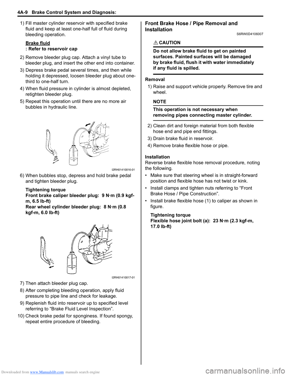
1) Fill master cylinder reservoir with specified brake
fluid and keep at least one-half full of fluid during
bleeding operation.
Brake fluid
: Refer to reservoir cap
2) Remove bleeder plug cap. Attach a vinyl tube to
bleeder plug, and insert the other end into container.
3) Depress brake pedal several times, and then while
holding it depressed, loosen bleeder plug about one-
third to one-half turn.
4) When fluid pressure in cylinder is almost depleted,
retighten bleeder plug.
5) Repeat this operation until there are no more air
bubbles in hydraulic line.
6) When bubbles stop, depress and hold brake pedal
and tighten bleeder plug.
Tightening torque
Front brake caliper bleeder plug: 9 N·m (0.9 kgf-
m, 6.5 lb-ft)
Rear wheel cylinder bleeder plug: 8 N·m (0.8
kgf-m, 6.0 lb-ft)
7) Then attach bleeder plug cap.
8) After completing bleeding operation, apply fluid
pressure to pipe line and check for leakage.
9) Replenish fluid into reservoir up to specified level
referring to “Brake Fluid Level Inspection”.
10) Check brake pedal for sponginess. If found spongy,
repeat entire procedure of bleeding.
Front Brake Hose / Pipe Removal and
Installation
S6RW0D4106007
CAUTION!
Do not allow brake fluid to get on painted
surfaces. Painted surfaces will be damaged
by brake fluid, flush it with water immediately
if any fluid is spilled.
Removal
1) Raise and support vehicle properly. Remove tire and
wheel.
NOTE
This operation is not necessary when
removing pipes connecting master cylinder.
2) Clean dirt and foreign material from both flexible
hose end and pipe end fittings.
3) Drain brake fluid in reservoir.
4) Remove brake flexible hose or pipe.
Installation
Reverse brake flexible hose removal procedure, noting
the following.
• Make sure that steering wheel is in straight-forward
position and flexible hose has not twist or kink.
• Install clamps and tighten nuts referring to “Front
Brake Hose / Pipe Construction”.
• Install brake flexible hose (1) to caliper as shown in
figure.
Tightening torque
Flexible hose joint bolt (a): 23 N·m (2.3 kgf-m,
17.0 lb-ft)
I2RH01410016-01
I2RH01410017-01
Page 582 of 1556
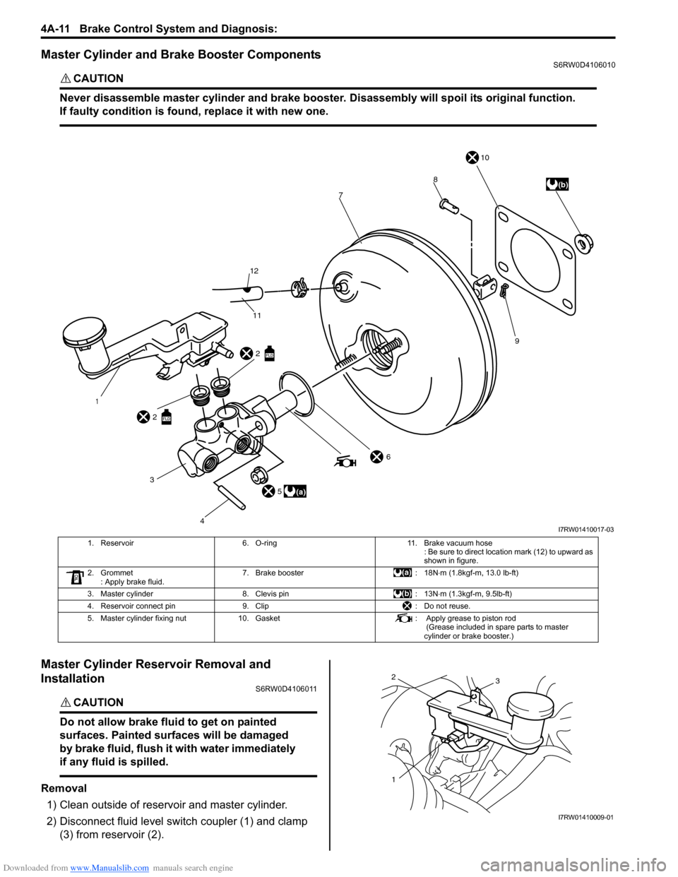
Downloaded from www.Manualslib.com manuals search engine 4A-11 Brake Control System and Diagnosis:
Master Cylinder and Brake Booster ComponentsS6RW0D4106010
CAUTION!
Never disassemble master cylinder and brake booster. Disassembly will spoil its original function.
If faulty condition is found, replace it with new one.
Master Cylinder Reservoir Removal and
Installation
S6RW0D4106011
CAUTION!
Do not allow brake fluid to get on painted
surfaces. Painted surfaces will be damaged
by brake fluid, flush it with water immediately
if any fluid is spilled.
Removal
1) Clean outside of reservoir and master cylinder.
2) Disconnect fluid level switch coupler (1) and clamp
(3) from reservoir (2).
4 2
2
1
(b) 10
9 8
7
11 12
6
3
5(a)
I7RW01410017-03
1. Reservoir 6. O-ring 11. Brake vacuum hose
: Be sure to direct location mark (12) to upward as
shown in figure.
2. Grommet
: Apply brake fluid. 7. Brake booster : 18N⋅m (1.8kgf-m, 13.0 lb-ft)
3. Master cylinder 8. Clevis pin : 13N⋅m (1.3kgf-m, 9.5lb-ft)
4. Reservoir connect pin 9. Clip : Do not reuse.
5. Master cylinder fixing nut 10. Gasket : Apply grease to piston rod
(Grease included in spare parts to master
cylinder or brake booster.)
2
13
I7RW01410009-01