cylinder SUZUKI SX4 2006 1.G Service Workshop Manual
[x] Cancel search | Manufacturer: SUZUKI, Model Year: 2006, Model line: SX4, Model: SUZUKI SX4 2006 1.GPages: 1556, PDF Size: 37.31 MB
Page 599 of 1556
Downloaded from www.Manualslib.com manuals search engine Rear Brakes: 4C-4
3) Remove return springs, brake shoes and adjuster.
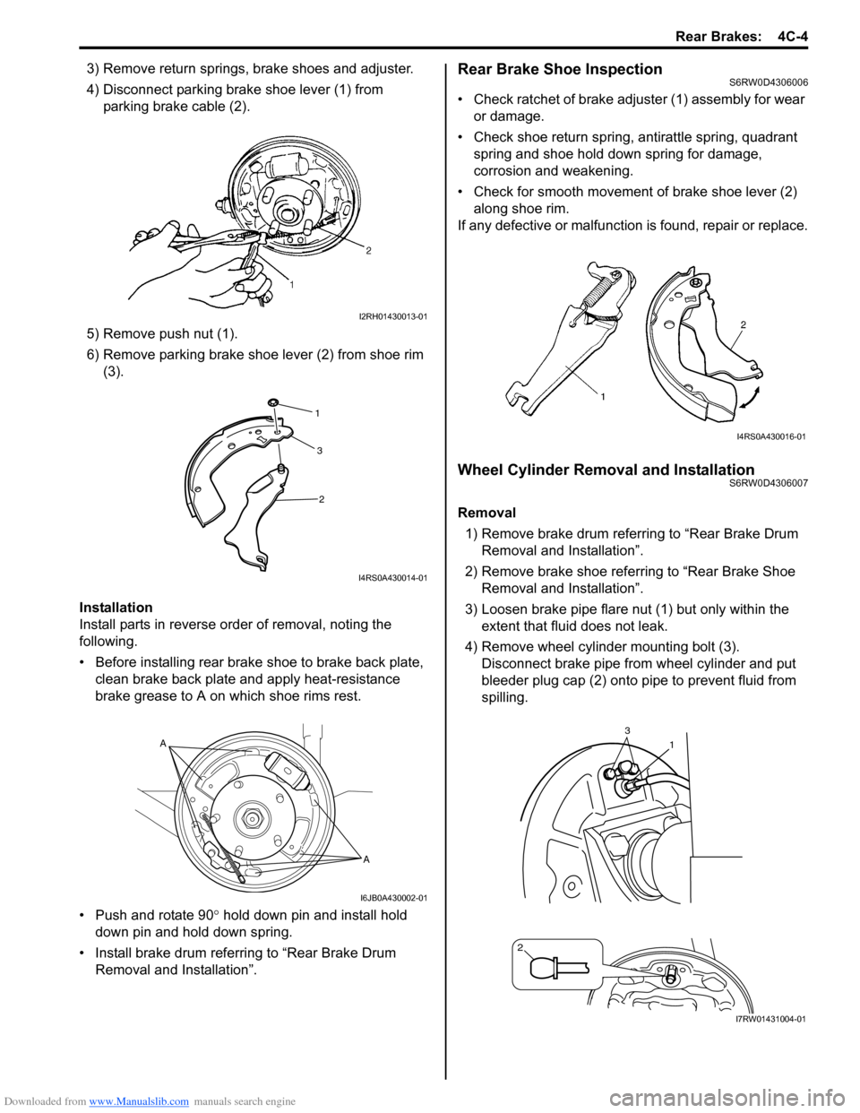
4) Disconnect parking brake shoe lever (1) from
parking brake cable (2).
5) Remove push nut (1).
6) Remove parking brake shoe lever (2) from shoe rim
(3).
Installation
Install parts in reverse order of removal, noting the
following.
• Before installing rear brake shoe to brake back plate,
clean brake back plate and apply heat-resistance
brake grease to A on which shoe rims rest.
• Push and rotate 90° hold down pin and install hold
down pin and hold down spring.
• Install brake drum referring to “Rear Brake Drum
Removal and Installation”.Rear Brake Shoe InspectionS6RW0D4306006
• Check ratchet of brake adjuster (1) assembly for wear
or damage.
• Check shoe return spring, antirattle spring, quadrant
spring and shoe hold down spring for damage,
corrosion and weakening.
• Check for smooth movement of brake shoe lever (2)
along shoe rim.
If any defective or malfunction is found, repair or replace.
Wheel Cylinder Removal and InstallationS6RW0D4306007
Removal
1) Remove brake drum referring to “Rear Brake Drum
Removal and Installation”.
2) Remove brake shoe referring to “Rear Brake Shoe
Removal and Installation”.
3) Loosen brake pipe flare nut (1) but only within the
extent that fluid does not leak.
4) Remove wheel cylinder mounting bolt (3).
Disconnect brake pipe from wheel cylinder and put
bleeder plug cap (2) onto pipe to prevent fluid from
spilling.
I2RH01430013-01
1
2 3
I4RS0A430014-01
A
A
I6JB0A430002-01
I4RS0A430016-01
1
2
3
I7RW01431004-01
Page 600 of 1556
Downloaded from www.Manualslib.com manuals search engine 4C-5 Rear Brakes:
Installation
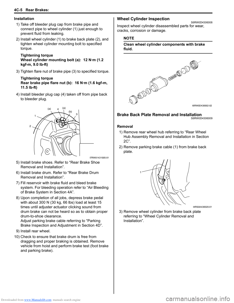
1) Take off bleeder plug cap from brake pipe and
connect pipe to wheel cylinder (1) just enough to
prevent fluid from leaking.
2) Install wheel cylinder (1) to brake back plate (2), and
tighten wheel cylinder mounting bolt to specified
torque.
Tightening torque
Wheel cylinder mounting bolt (a): 12 N·m (1.2
kgf-m, 9.0 lb-ft)
3) Tighten flare nut of brake pipe (3) to specified torque.
Tightening torque
Rear brake pipe flare nut (b): 16 N·m (1.6 kgf-m,
11.5 lb-ft)
4) Install bleeder plug cap (4) taken off from pipe back
to bleeder plug.
5) Install brake shoes. Refer to “Rear Brake Shoe
Removal and Installation”.
6) Install brake drum. Refer to “Rear Brake Drum
Removal and Installation”.
7) Fill reservoir with brake fluid and bleed brake
system. For bleeding operation refer to “Air Bleeding
of Brake System in Section 4A”.
8) Upon completion of all jobs, depress brake pedal
with about 300 N (30 kg, 66 lbs) load at least 15
times until adjuster actuator clicking sound from
drum brake can not be heard so as to obtain proper
drum-to-shoe clearance.
Adjust parking brake cable referring to “Parking
Brake Inspection and Adjustment in Section 4D”.
9) Install rear wheel.
10) Check to ensure that brake drum is free from
dragging and proper braking is obtained. Remove
vehicle from hoist and perform brake test (foot brake
and parking brake).Wheel Cylinder InspectionS6RW0D4306008
Inspect wheel cylinder disassembled parts for wear,
cracks, corrosion or damage.
NOTE
Clean wheel cylinder components with brake
fluid.
Brake Back Plate Removal and InstallationS6RW0D4306009
Removal
1) Remove rear wheel hub referring to “Rear Wheel
Hub Assembly Removal and Installation in Section
2C”.
2) Remove parking brake cable (1) from brake back
plate.
3) Remove wheel cylinder from brake back plate
referring to “Wheel Cylinder Removal and
Installation”.
(b)3
4(a)
(a)
1
2
I7RW01431005-01
I6RW0D430002-02
1
I4RS0A430020-01
Page 601 of 1556
Downloaded from www.Manualslib.com manuals search engine Rear Brakes: 4C-6
Installation
Install brake back plate by reversing removal procedure,
noting the instructions.
CAUTION!
Never reuse rear wheel hub mounting bolts.
• Install rear wheel hub and brake back plate, and then
tighten mounting bolt. Refer to “Rear Drum Brake
Components”.
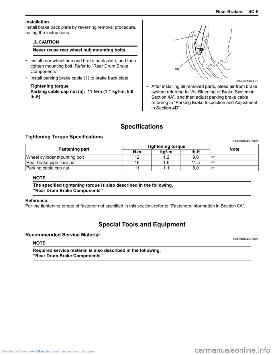
• Install parking brake cable (1) to brake back plate.
Tightening torque
Parking cable cap nut (a): 11 N·m (1.1 kgf-m, 8.0
lb-ft)• After installing all removed parts, bleed air from brake
system referring to “Air Bleeding of Brake System in
Section 4A”. and then adjust parking brake cable
referring to “Parking Brake Inspection and Adjustment
in Section 4D”.
Specifications
Tightening Torque SpecificationsS6RW0D4307001
NOTE
The specified tightening torque is also described in the following.
“Rear Drum Brake Components”
Reference:
For the tightening torque of fastener not specified in this section, refer to “Fasteners Information in Section 0A”.
Special Tools and Equipment
Recommended Service MaterialS6RW0D4308001
NOTE
Required service material is also described in the following.
“Rear Drum Brake Components”
1
(a)
I4RS0A430024-01
Fastening partTightening torque
Note
N⋅mkgf-mlb-ft
Wheel cylinder mounting bolt 12 1.2 9.0�)
Rear brake pipe flare nut 16 1.6 11.5�)
Parking cable cap nut 11 1.1 8.0�)
Page 607 of 1556
Downloaded from www.Manualslib.com manuals search engine ABS: 4E-2
General Description
ABS DescriptionS6RW0D4501001
The ABS (Antilock Brake System) controls the fluid
pressure applied to the wheel cylinder of each brake
from the master cylinder so that each wheel is not locked
even when hard braking is applied.
This ABS has also the following function.
While braking is applied, but before ABS control
becomes effective, braking force is distributed between
the front and rear so as to prevent the rear wheels from
being locked too early for better stability of the vehicle.
The main component parts of this ABS include the
following parts in addition to those of the conventional
brake system.
• Wheel speed sensor which senses revolution speed
of each wheel and outputs its signal.
Rear wheel speed sensor of 4WD vehicle is
integrated in rear wheel hub assembly and supplied
as rear wheel hub assembly part.
Front wheel speed sensor and rear wheel speed
sensor of 2WD model are separated from wheel hub
assembly and supplied as spare parts.
• ABS warning light which lights to inform abnormality
when system fails to operate properly.• ABS hydraulic unit / control module assembly is
incorporated ABS control module, ABS hydraulic unit
(actuator assembly), solenoid valve power supply
driver (transistor), solenoid valve driver (transistor),
pump motor driver (transistor).
– ABS control module which sends operation signal
to ABS hydraulic unit to control fluid pressure
applied to each wheel cylinder based on signal
from each wheel speed sensor so as to prevent
wheel from locking.
– ABS hydraulic unit which operates according to
signal from ABS control module to control fluid
pressure applied to wheel cylinder of each 4
wheels.
– Solenoid valve power supply driver (transistor)
which supplies power to solenoid valve in ABS
hydraulic unit.
– Solenoid valve driver (transistor) which controls
each solenoid valves in ABS hydraulic unit.
– Pump motor driver (transistor) which supplies
power to pump motor in ABS hydraulic unit.
• G sensor which detects body deceleration speed for
4WD model.
This ABS is equipped with Electronic Brake force
Distribution (EBD) system that controls a fluid pressure
of rear wheels to best condition, which is the same
function as that of proportioning valve, by the signal from
wheel sensor independently of change of load due to
load capacity and so on. And if the EBD system fails to
operate properly, the brake warning light lights to inform
abnormality.
Page 647 of 1556

Downloaded from www.Manualslib.com manuals search engine Table of Contents 5-iii
Diagnostic Information and Procedures ............ 5B-5
Manual Transaxle Symptom Diagnosis............... 5B-5
Repair Instructions .............................................. 5B-5
Manual Transaxle Oil Level Check ..................... 5B-5
Manual Transaxle Oil Change ............................ 5B-6
Differential Side Oil Seal Replacement ............... 5B-7
Gear Shift Control Lever and Cable
Components...................................................... 5B-8
Gear Shift Control Lever and Cable Removal
and Installation .................................................. 5B-9
Gear Select Control Cable Adjustment ............... 5B-9
Back Up Light Switch Removal and
Installation ....................................................... 5B-10
Back Up Light Switch Inspection ....................... 5B-10
Manual Transaxle Unit Components ................. 5B-11
Manual Transaxle Unit Dismounting and
Remounting..................................................... 5B-12
Gear Shift and Select Shaft Assembly
Components.................................................... 5B-13
Gear Shift and Select Shaft Assembly
Removal and Installation................................. 5B-14
Gear Shift and Select Shaft Assembly
Disassembly and Reassembly ........................ 5B-15
Manual Transaxle Assembly Components........ 5B-16
Fifth Gear Disassembly and Reassembly ......... 5B-17
Manual Transaxle Assembly Disassembly
and Reassembly ............................................. 5B-19
Right Case Disassembly and Reassembly ....... 5B-24
Left Case Disassembly and Reassembly.......... 5B-25
Input Shaft and Countershaft Components....... 5B-27
Input Shaft Disassembly and Reassembly........ 5B-28
Countershaft Disassembly and Reassembly .... 5B-31
Gear Shift Shaft Components ........................... 5B-35
5th and Reverse Gear Shift Shafts
Disassembly and Reassembly ........................ 5B-35
Gear Shift Shaft and Fork Inspection ................ 5B-35
Differential Components ................................... 5B-36Differential Disassembly and Reassembly ........ 5B-36
Specifications .....................................................5B-38
Tightening Torque Specifications ...................... 5B-38
Special Tools and Equipment ...........................5B-39
Recommended Service Material ....................... 5B-39
Special Tool ...................................................... 5B-39
Clutch ....................................................... 5C-1
General Description .............................................5C-1
Clutch (Hydraulic Type) Construction .................5C-1
Diagnostic Information and Procedures ............5C-2
Clutch System Symptom Diagnosis ....................5C-2
Repair Instructions ..............................................5C-3
Clutch Pedal Inspection ......................................5C-3
Clutch Fluid Level Inspection ..............................5C-3
Air Bleeding of Clutch System.............................5C-3
Clutch Fluid Pipe and Hose Location ..................5C-4
Clutch Fluid Pipe Removal and Installation.........5C-4
Clutch Fluid Pipe Inspection................................5C-4
Clutch Master Cylinder Removal and
Installation .........................................................5C-5
Clutch Operating Cylinder Assembly
Removal and Installation ...................................5C-5
Clutch Operating Cylinder Assembly
Inspection ..........................................................5C-6
Clutch Cover, Clutch Disc and Flywheel
Components ......................................................5C-6
Clutch Cover, Clutch Disc and Flywheel
Removal and Installation ...................................5C-7
Clutch Cover, Clutch Disc and Flywheel
Inspection ..........................................................5C-8
Specifications .......................................................5C-9
Tightening Torque Specifications ........................5C-9
Special Tools and Equipment ...........................5C-10
Recommended Service Material .......................5C-10
Special Tool ......................................................5C-10
Page 735 of 1556

Downloaded from www.Manualslib.com manuals search engine Automatic Transmission/Transaxle: 5A-87
2) Remove adjuster (cable end) from select lever pin of
select lever assembly.
3) Remove adjuster (cable end) from select lever pin of
select lever assembly.
4) Release lock plate (1) which restrict moving of cable
end holder (2).
5) Push cable end holder (1) out from eye-end (2) using
an appropriate tool (3) to disengage cable.
6) Shift select lever to “N” position.
7) Apply grease to select lever pin and install adjuster
(cable end) to it.
: Grease 99000–25011 (SUZUKI Super Grease
A)
8) With both select lever and transmission range
sensor kept each “N” position, drive cable end holder
(1) in until it locks cable.
9) Slide lock plate (2) to secure cable end holder in
position.
10) After select cable was installed, check for the
following.
• Push vehicle with select lever shifted to “P” range.
Vehicle should not move.
• Vehicle can not be driven in “N” range.• Vehicle can be driven in “D”, “3”, “2” and “L”
ranges.
• Vehicle can be backed in “R” range.
Key Interlock Cable Removal and InstallationS6RW0D5106026
NOTE
Don’t bend interlock cable excessively when
removing and installing it, or system will not
operate correctly.
Removal
1) If the vehicle is equipped with air bag system,
disconnect negative cable at battery and disable air
bag system, referring to “Disabling Air Bag System in
Section 8B”.
2) Remove steering column cover.
3) Turn ignition switch to ACC position.
4) Pull out key interlock cable (1) from key cylinder
cover (2) while pressing checkhook with slotted
screwdriver (3) or the like.
5) Turn ignition switch to LOCK position.
6) Remove console box referring to “Console Box
Components in Section 9H”.
7) Detach cable end (1) from interlock cam (2) while
pressing claws (3) of interlock cam boss.
At this time, be careful not to cause damage to its
claws.
Detach cable casing cap (4) from bracket (5) while
pressing checkhook.
8) Remove interlock cable.
I2RH01510046-01
I2RH01510047-01
I3RM0B510037-01
2
13I5RW0C510045-01
4
5 3 12
4
I5RW0C510046-01
Page 736 of 1556
![SUZUKI SX4 2006 1.G Service Workshop Manual Downloaded from www.Manualslib.com manuals search engine 5A-88 Automatic Transmission/Transaxle:
Installation
1) Lay interlock cable to its original cabling route.
C
1 2
3
4
5
61
9 [C] [A]
7
12
3
4
5 SUZUKI SX4 2006 1.G Service Workshop Manual Downloaded from www.Manualslib.com manuals search engine 5A-88 Automatic Transmission/Transaxle:
Installation
1) Lay interlock cable to its original cabling route.
C
1 2
3
4
5
61
9 [C] [A]
7
12
3
4
5](/img/20/7612/w960_7612-735.png)
Downloaded from www.Manualslib.com manuals search engine 5A-88 Automatic Transmission/Transaxle:
Installation
1) Lay interlock cable to its original cabling route.
C
1 2
3
4
5
61
9 [C] [A]
7
12
3
4
567
8
2 [B]
I5RW0C510073-01
[A]: LH steering vehicle 2. Clamp 6. EPS control module
[B]: RH steering vehicle 3. Steering lock assembly / Steering lock unit (if equipped with Keyless
start system)7. Brake switch bracket
[C]: View C 4. Key cylinder cover 8. Wiring harness
1. Key interlock cable 5. Select lever assembly 9. Marking
Page 737 of 1556

Downloaded from www.Manualslib.com manuals search engine Automatic Transmission/Transaxle: 5A-89
2) Turn ignition switch to ACC position.
3) Insert cable casing cap (1) into key cylinder cover (2)
securely.
4) Pull out lock button (1) of select lever side cable end
(2).
5) Shift select lever to “N” position.
NOTE
If select lever is in “P” position, shift select
lever referring to “Select Lever Inspection”.
6) Install cable casing cap (3) to bracket (4).
7) Connect cable end (1) to interlock cam (2) with
ignition switch turned to ACC position.
8) Drive lock button (5) in cable end until it locks cable
expansion and contraction.9) With select lever set at “P” position, turn ignition key
to ACC position and then check for the following
conditions.
• With knob button released, ignition key can be
turned from ACC position to LOCK position.
• With knob button pressed, ignition key cannot be
turned from ACC position to LOCK position.
10) Install knee protector to steering column.
11) Install steering column cover.
12) If the vehicle is equipped with air bag system,
connect negative cable at battery and enable air bag
system, referring to “Enabling Air Bag System in
Section 8B”.
Transmission Range Sensor Inspection and
Adjustment
S6RW0D5106009
1) Shift manual select lever (4) to “N” range.
2) Check that needle direction shaped on lock washer
(2) and “N” reference line (1) on transmission range
sensor are aligned. If not, loosen sensor bolts (3)
and align them.
Tightening torque
Transmission range sensor bolt (a): 5.5 N·m (
0.55 kgf-m, 4.0 lb-ft)
2
1I5RW0C510047-01
1 1
2
I2RH01510086-01
3
4 12
3 5
I5RW0C510048-01
1
3, (a) 4
2
I2RH0B510041-01
Page 776 of 1556
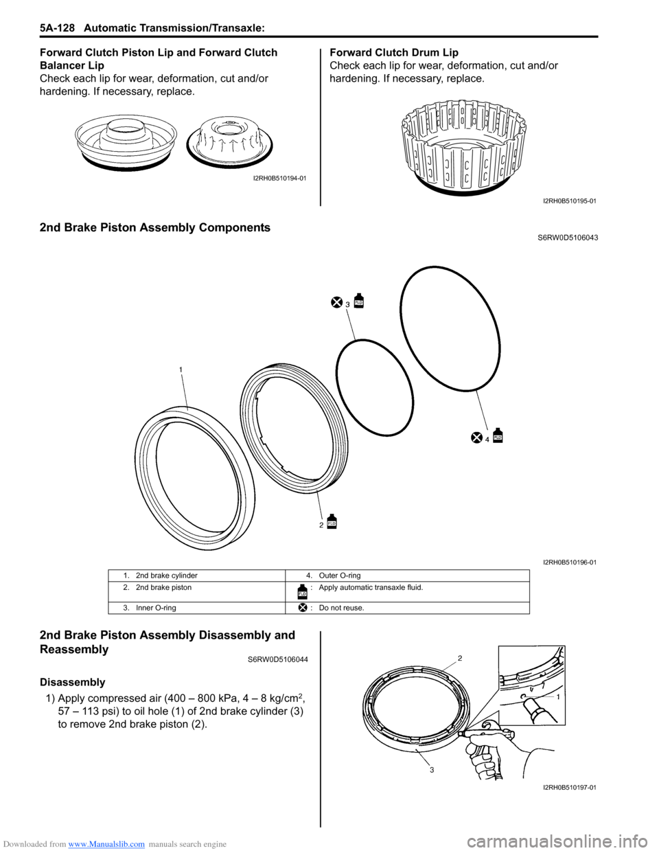
Downloaded from www.Manualslib.com manuals search engine 5A-128 Automatic Transmission/Transaxle:
Forward Clutch Piston Lip and Forward Clutch
Balancer Lip
Check each lip for wear, deformation, cut and/or
hardening. If necessary, replace.Forward Clutch Drum Lip
Check each lip for wear, deformation, cut and/or
hardening. If necessary, replace.
2nd Brake Piston Assembly ComponentsS6RW0D5106043
2nd Brake Piston Assembly Disassembly and
Reassembly
S6RW0D5106044
Disassembly
1) Apply compressed air (400 – 800 kPa, 4 – 8 kg/cm
2,
57 – 113 psi) to oil hole (1) of 2nd brake cylinder (3)
to remove 2nd brake piston (2).
I2RH0B510194-01
I2RH0B510195-01
I2RH0B510196-01
1. 2nd brake cylinder 4. Outer O-ring
2. 2nd brake piston : Apply automatic transaxle fluid.
3. Inner O-ring : Do not reuse.
I2RH0B510197-01
Page 777 of 1556
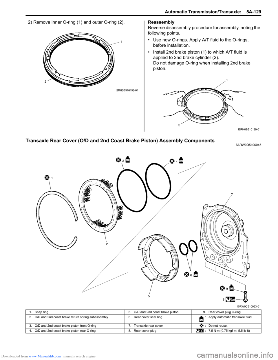
Downloaded from www.Manualslib.com manuals search engine Automatic Transmission/Transaxle: 5A-129
2) Remove inner O-ring (1) and outer O-ring (2).Reassembly
Reverse disassembly procedure for assembly, noting the
following points.
• Use new O-rings. Apply A/T fluid to the O-rings,
before installation.
• Install 2nd brake piston (1) to which A/T fluid is
applied to 2nd brake cylinder (2).
Do not damage O-ring when installing 2nd brake
piston.
Transaxle Rear Cover (O/D and 2nd Coast Brake Piston) Assembly ComponentsS6RW0D5106045
I2RH0B510198-01
I2RH0B510199-01
I5RW0C510063-01
1. Snap ring 5. O/D and 2nd coast brake piston 9. Rear cover plug O-ring
2. O/D and 2nd coast brake return spring subassembly 6. Rear cover seal ring : Apply automatic transaxle fluid.
3. O/D and 2nd coast brake piston front O-ring 7. Transaxle rear cover : Do not reuse.
4. O/D and 2nd coast brake piston rear O-ring 8. Rear cover plug : 7.5 N⋅m (0.75 kgf-m, 5.5 lb-ft)