cylinder SUZUKI SX4 2006 1.G Service Workshop Manual
[x] Cancel search | Manufacturer: SUZUKI, Model Year: 2006, Model line: SX4, Model: SUZUKI SX4 2006 1.GPages: 1556, PDF Size: 37.31 MB
Page 1496 of 1556

Downloaded from www.Manualslib.com manuals search engine 10B-23 Body Electrical Control System:
BCM connector “G04”E04-13 — — —
E04-14 — — —
Terminal Circuit Normal voltage Condition
G04-1CAN communication line (low)
for DLC*1.6 – 2.5 V
Refer to “Reference waveform No. 3: ” G04-2CAN communication line (low)
for each control module*1.6 – 2.5 V
G04-3CAN communication line
(high) for DLC*2.5 – 3.6 V
G04-4CAN communication line
(high) for each control module*2.5 – 3.6 V
G04-5Serial communication line of
data link connector 7 – 12 V Ignition switch is at ON position
G04-6 — — —
G04-7 — — —
G04-8 Theft deterrent light10 – 14 V Theft deterrent light is not lit up
0 V Theft deterrent light is lit up
G04-9 — — —
G04-10 — — —
G04-11Serial communication line for
information display and HVAC
control module (if equipped)*0 – 1 V
↑↓
10 – 14 VRefer to “Reference waveform No. 5: ”
G04-12Ground for keyless entry
receiver (if equipped)0 V —
G04-13Power supply for keyless
entry receiver (if equipped)4 – 6 V Ignition switch is at all positions
G04-14Signal for keyless entry
receiver (if equipped)*0 – 1 V
↑↓
4 – 6 VRefer to “Reference waveform No. 6: ”
G04-15 Vehicle speed signal output*0 – 1 V
↑↓
4 – 6VRefer to “Reference waveform No. 7: ”
G04-16 Key reminder switch10 – 14 V Ignition key is inserted to ignition key cylinder
0 VIgnition key is pulled out from ignition key
cylinder
G04-17Rear end door window
defogger switch*3 – 14 V Refer to “Reference waveform No. 8: ”
0 VIgnition switch is at ON position and rear end
door window defogger switch is pushed
G04-18 A/C switch (if equipped)*3 – 14 V Refer to “Reference waveform No. 8: ”
0 VIgnition switch is at ON position, blower speed
selector is at any position other than OFF
position and A/C switch is at ON position
G04-19 — — —
G04-20 — — —
G04-21 Rear wiper INT switch*0 – 1 V
↑↓
10 – 14 VRefer to “Reference waveform No. 9: ”
0 VIgnition switch is at ON position and rear
wiper switch is at INT position
G04-22 Rear wiper low switch*0 – 1 V
↑↓
10 – 14 VRefer to “Reference waveform No. 9: ”
0 VIgnition switch is at ON position and rear
wiper switch is at LOW position Terminal Circuit Normal voltage Condition
Page 1498 of 1556

Downloaded from www.Manualslib.com manuals search engine 10B-25 Body Electrical Control System:
Junction block connector “L314”
Junction block connector “L315”Terminal Circuit Normal voltage Condition
L314-4 Ground for BCM 0 V Ignition switch is at all positions
L314-6Right side door mirror heater
(if equipped)10 – 14 VEngine is running and rear end door window
defogger is in operation
0 VEngine is running and rear end door window
defogger is not in operation
L314-7Left side door mirror heater (if
equipped)10 – 14 VEngine is running and rear end door window
defogger is in operation
0 VEngine is running and rear end door window
defogger is not in operation
L314-8Rear end door window
defogger wire10 – 14 VEngine is running and rear end door window
defogger is in operation
0 VEngine is running and rear end door window
defogger is not in operation
L314-9 Rear wiper control10 – 14 VIgnition switch is at ON position and rear
wiper is not in operation
0 VIgnition switch is at ON position and rear
wiper is in operation
Terminal Circuit Normal voltage Condition
L315-1Door lock actuator control
(Dead lock) (if equipped)10 – 14 VDriver side key cylinder is turned to lock twice
with in 3 seconds
0 VManual door lock switch is at any position
other than LOCK position and driver side door
key cylinder switch is at any position other
than LOCK position
L315-9Door lock actuator control
(Unlock) (if equipped)10 – 14 VUnlock signal is output for rear door lock
actuator
0 VUnlock signal is not output for rear door lock
actuator
L315-10Door lock actuator control
(Lock) (if equipped)10 – 14 V Lock signal is output for all door lock actuators
0 VLock signal is not output for all door lock
actuators
Page 1502 of 1556

Downloaded from www.Manualslib.com manuals search engine 10B-29 Body Electrical Control System:
5) Disconnect connectors from BCM and junction
block.
6) Detach wiring harness clamp from junction block.
Installation
Reverse removal procedure for installation, noting
following points.
• Connect connectors securely.
• Enable air bag system referring to “Enabling Air Bag
System in Section 8B”.
• With keyless entry system (other than keyless start
model), if BCM is replaced, register transmitter code
into BCM, referring to “Programming Transmitter
Code for Keyless Entry System (Other than Keyless
Start Model) in Section 9F”.
Security Alarm Mode Selection Procedure (If
Equipped)
S6RW0DA206005
Security alarm mode can be selected by performing the
following procedure.
1) Confirm that all doors are closed, all doors are
unlocked and ignition key is inserted in ignition key
cylinder.
2) Remove ignition key from ignition key cylinder.
3) Perform Step a) through e) described below within
15 seconds.
a) Insert ignition key (1) in ignition key cylinder (2).
b) Remove ignition key from ignition key cylinder.
c) Repeat Step a) and b) twice.
d) Insert ignition key in ignition key cylinder.
e) Push lock side (3) of driver side manual lock
switch (4) 3 times.4) When Step 3) is completed, the mode changes to
the next one automatically. The warning buzzer
(located in BCM) sounds by the number of specified
for each mode as follows.
• Changed from A mode to B mode: Buzzer sounds
4 times
• Changed from B mode to A mode: Buzzer sounds
once
Outside Air Temperature Sensor Removal and
Installation
S6RW0DA206002
For removal and installation, refer to “Outside Air
Temperature Sensor Removal and Installation (If
Equipped) in Section 9C”.
Outside Air Temperature Sensor InspectionS6RW0DA206003
For inspection, refer to “Outside Air Temperature Sensor
Inspection (If Equipped) in Section 9C”.
Special Tools and Equipment
Special ToolS6RW0DA208001
1 2
4
3
I7JB01A20007-01
SUZUKI scan tool
—
This kit includes following
items. 1. Tech 2, 2. PCMCIA
card, 3. DLC cable, 4. SAE
16/19 adapter, 5. Cigarette
cable, 6. DLC loop back
adapter, 7. Battery power
cable, 8. RS232 cable, 9.
RS232 adapter, 10. RS232
loop back connector, 11.
Storage case, 12. �)
Page 1520 of 1556
Downloaded from www.Manualslib.com manuals search engine 10C-18 Immobilizer Control System:
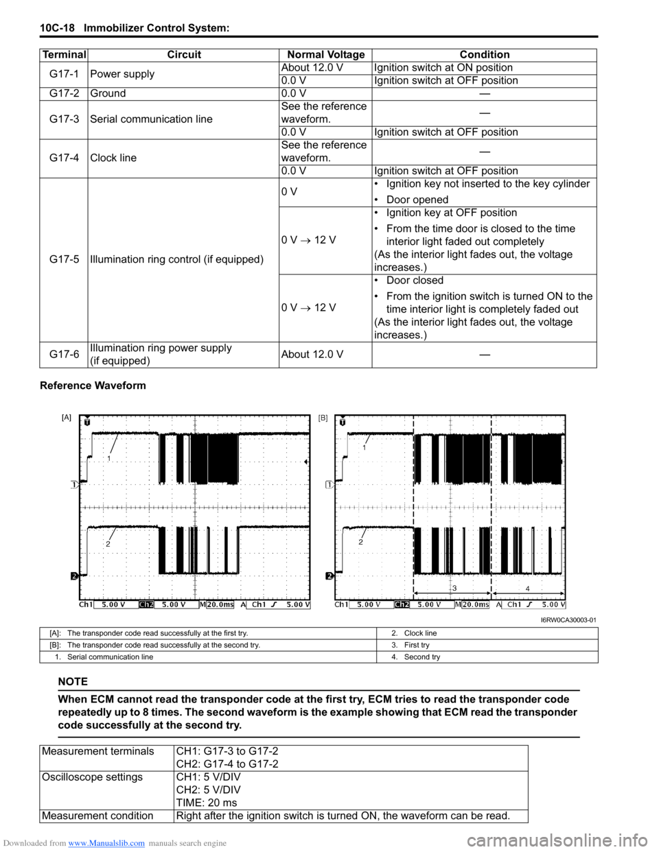
Reference Waveform
NOTE
When ECM cannot read the transponder code at the first try, ECM tries to read the transponder code
repeatedly up to 8 times. The second waveform is the example showing that ECM read the transponder
code successfully at the second try.
Terminal Circuit Normal Voltage Condition
G17-1 Power supplyAbout 12.0 V Ignition switch at ON position
0.0 V Ignition switch at OFF position
G17-2 Ground 0.0 V —
G17-3 Serial communication lineSee the reference
waveform.—
0.0 V Ignition switch at OFF position
G17-4 Clock lineSee the reference
waveform.—
0.0 V Ignition switch at OFF position
G17-5 Illumination ring control (if equipped)0 V• Ignition key not inserted to the key cylinder
• Door opened
0 V → 12 V• Ignition key at OFF position
• From the time door is closed to the time
interior light faded out completely
(As the interior light fades out, the voltage
increases.)
0 V → 12 V• Door closed
• From the ignition switch is turned ON to the
time interior light is completely faded out
(As the interior light fades out, the voltage
increases.)
G17-6Illumination ring power supply
(if equipped)About 12.0 V —
I6RW0CA30003-01
[A]: The transponder code read successfully at the first try. 2. Clock line
[B]: The transponder code read successfully at the second try. 3. First try
1. Serial communication line 4. Second try
Measurement terminals CH1: G17-3 to G17-2
CH2: G17-4 to G17-2
Oscilloscope settings CH1: 5 V/DIV
CH2: 5 V/DIV
TIME: 20 ms
Measurement condition Right after the ignition switch is turned ON, the waveform can be read.
Page 1527 of 1556
Downloaded from www.Manualslib.com manuals search engine Keyless Start System: 10E-5
Operation Area of Remote ControllerS6RW0DA501005
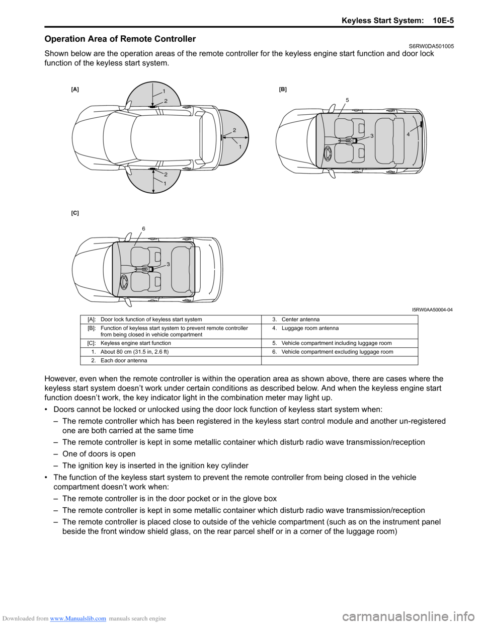
Shown below are the operation areas of the remote controller for the keyless engine start function and door lock
function of the keyless start system.
However, even when the remote controller is within the operation area as shown above, there are cases where the
keyless start system doesn’t work under certain conditions as described below. And when the keyless engine start
function doesn’t work, the key indicator light in the combination meter may light up.
• Doors cannot be locked or unlocked using the door lock function of keyless start system when:
– The remote controller which has been registered in the keyless start control module and another un-registered
one are both carried at the same time
– The remote controller is kept in some metallic container which disturb radio wave transmission/reception
– One of doors is open
– The ignition key is inserted in the ignition key cylinder
• The function of the keyless start system to prevent the remote controller from being closed in the vehicle
compartment doesn’t work when:
– The remote controller is in the door pocket or in the glove box
– The remote controller is kept in some metallic container which disturb radio wave transmission/reception
– The remote controller is placed close to outside of the vehicle compartment (such as on the instrument panel
beside the front window shield glass, on the rear parcel shelf or in a corner of the luggage room)
[A][B]
[C]1
1
1
2
2
25
34
6
3
I5RW0AA50004-04
[A]: Door lock function of keyless start system 3. Center antenna
[B]: Function of keyless start system to prevent remote controller
from being closed in vehicle compartment4. Luggage room antenna
[C]: Keyless engine start function 5. Vehicle compartment including luggage room
1. About 80 cm (31.5 in, 2.6 ft) 6. Vehicle compartment excluding luggage room
2. Each door antenna
Page 1533 of 1556
Downloaded from www.Manualslib.com manuals search engine Keyless Start System: 10E-11
DTC CheckS6RW0DA504007
1) Check to make sure that all doors are closed.
2) Open driver side door window glass and door.
3) Check to make sure that ignition key is not inserted
in ignition key cylinder. If it is, remove it.
4) Perform “Key Indicator Light Check”.
5) Close driver side door and within 15 seconds after
that, perform Steps a) through e) described below.
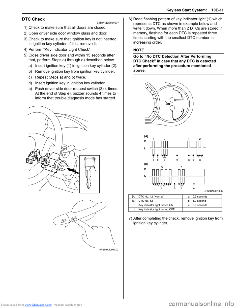
a) Insert ignition key (1) in ignition key cylinder (2).
b) Remove ignition key from ignition key cylinder.
c) Repeat Steps a) and b) twice.
d) Insert ignition key in ignition key cylinder.
e) Push driver side door request switch (3) 4 times.
At the end of Step e), buzzer sounds 4 times to
inform that trouble diagnosis mode has started.6) Read flashing pattern of key indicator light (1) which
represents DTC as shown in example below and
write it down. When more than 2 DTCs are stored in
memory, flashing for each DTC is repeated three
times starting with the smallest DTC number in
increasing order.
NOTE
Go to “No DTC Detection After Performing
DTC Check” in case that any DTC is detected
after performing the procedure mentioned
above.
7) After completing the check, remove ignition key from
ignition key cylinder.
2
1
3
I4RS0BA50009-02
[A]: DTC No. 12 (Normal) a: 0.3 seconds
[B]: DTC No. 52 b: 1.0 second
H: Key indicator light turned ON c: 3.0 seconds
L: Key indicator light turned OFF
bc a a
[A]
H
L
H
L [B]
52
bac a 2 11baa2
1
I4RS0BA50010-02
Page 1534 of 1556
Downloaded from www.Manualslib.com manuals search engine 10E-12 Keyless Start System:
DTC TableS6RW0DA504008
DTC ClearanceS6RW0DA504009
1) Perform Steps 1) through 5) of DTC check procedure
and have DTC indicated.
2) Open driver side door.
3) Close driver side door and within 10 seconds after
that, perform Steps a) to c) described below.
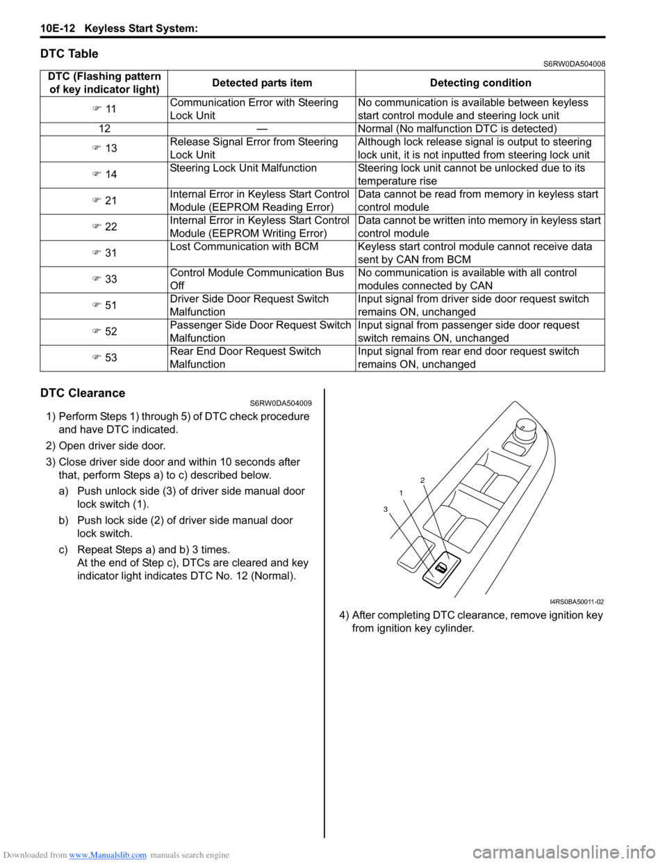
a) Push unlock side (3) of driver side manual door
lock switch (1).
b) Push lock side (2) of driver side manual door
lock switch.
c) Repeat Steps a) and b) 3 times.
At the end of Step c), DTCs are cleared and key
indicator light indicates DTC No. 12 (Normal).
4) After completing DTC clearance, remove ignition key
from ignition key cylinder. DTC (Flashing pattern
of key indicator light)Detected parts item Detecting condition
�) 11Communication Error with Steering
Lock UnitNo communication is available between keyless
start control module and steering lock unit
12 — Normal (No malfunction DTC is detected)
�) 13Release Signal Error from Steering
Lock UnitAlthough lock release signal is output to steering
lock unit, it is not inputted from steering lock unit
�) 14Steering Lock Unit Malfunction Steering lock unit cannot be unlocked due to its
temperature rise
�) 21Internal Error in Keyless Start Control
Module (EEPROM Reading Error)Data cannot be read from memory in keyless start
control module
�) 22Internal Error in Keyless Start Control
Module (EEPROM Writing Error)Data cannot be written into memory in keyless start
control module
�) 31Lost Communication with BCM Keyless start control module cannot receive data
sent by CAN from BCM
�) 33Control Module Communication Bus
OffNo communication is available with all control
modules connected by CAN
�) 51Driver Side Door Request Switch
MalfunctionInput signal from driver side door request switch
remains ON, unchanged
�) 52Passenger Side Door Request Switch
MalfunctionInput signal from passenger side door request
switch remains ON, unchanged
�) 53Rear End Door Request Switch
MalfunctionInput signal from rear end door request switch
remains ON, unchanged
1
32
I4RS0BA50011-02
Page 1536 of 1556
Downloaded from www.Manualslib.com manuals search engine 10E-14 Keyless Start System:
Keyless Start System Operation InspectionS6RW0DA504011
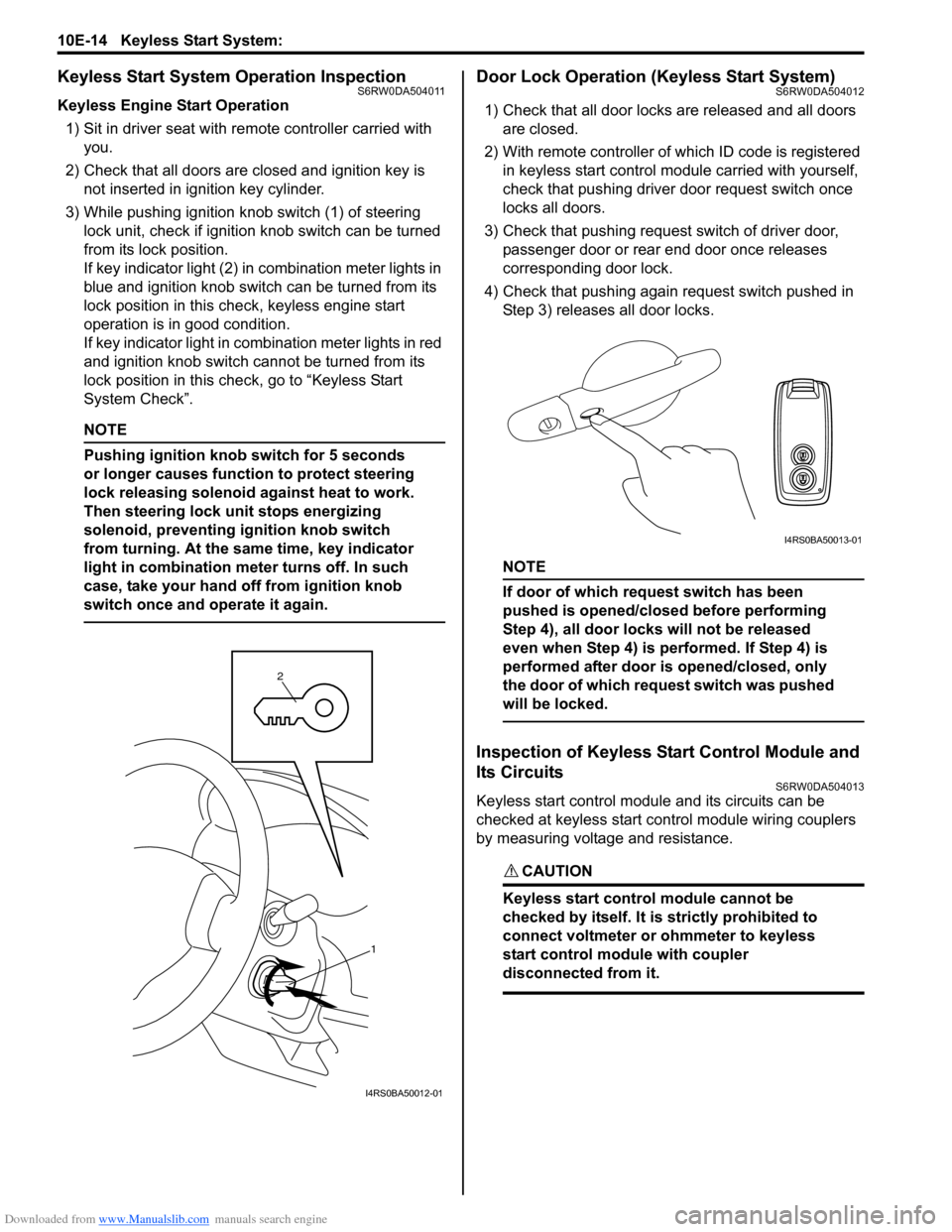
Keyless Engine Start Operation
1) Sit in driver seat with remote controller carried with
you.
2) Check that all doors are closed and ignition key is
not inserted in ignition key cylinder.
3) While pushing ignition knob switch (1) of steering
lock unit, check if ignition knob switch can be turned
from its lock position.
If key indicator light (2) in combination meter lights in
blue and ignition knob switch can be turned from its
lock position in this check, keyless engine start
operation is in good condition.
If key indicator light in combination meter lights in red
and ignition knob switch cannot be turned from its
lock position in this check, go to “Keyless Start
System Check”.
NOTE
Pushing ignition knob switch for 5 seconds
or longer causes function to protect steering
lock releasing solenoid against heat to work.
Then steering lock unit stops energizing
solenoid, preventing ignition knob switch
from turning. At the same time, key indicator
light in combination meter turns off. In such
case, take your hand off from ignition knob
switch once and operate it again.
Door Lock Operation (Keyless Start System)S6RW0DA504012
1) Check that all door locks are released and all doors
are closed.
2) With remote controller of which ID code is registered
in keyless start control module carried with yourself,
check that pushing driver door request switch once
locks all doors.
3) Check that pushing request switch of driver door,
passenger door or rear end door once releases
corresponding door lock.
4) Check that pushing again request switch pushed in
Step 3) releases all door locks.
NOTE
If door of which request switch has been
pushed is opened/closed before performing
Step 4), all door locks will not be released
even when Step 4) is performed. If Step 4) is
performed after door is opened/closed, only
the door of which request switch was pushed
will be locked.
Inspection of Keyless Start Control Module and
Its Circuits
S6RW0DA504013
Keyless start control module and its circuits can be
checked at keyless start control module wiring couplers
by measuring voltage and resistance.
CAUTION!
Keyless start control module cannot be
checked by itself. It is strictly prohibited to
connect voltmeter or ohmmeter to keyless
start control module with coupler
disconnected from it.
1 2
I4RS0BA50012-01
I4RS0BA50013-01
Page 1537 of 1556
Downloaded from www.Manualslib.com manuals search engine Keyless Start System: 10E-15
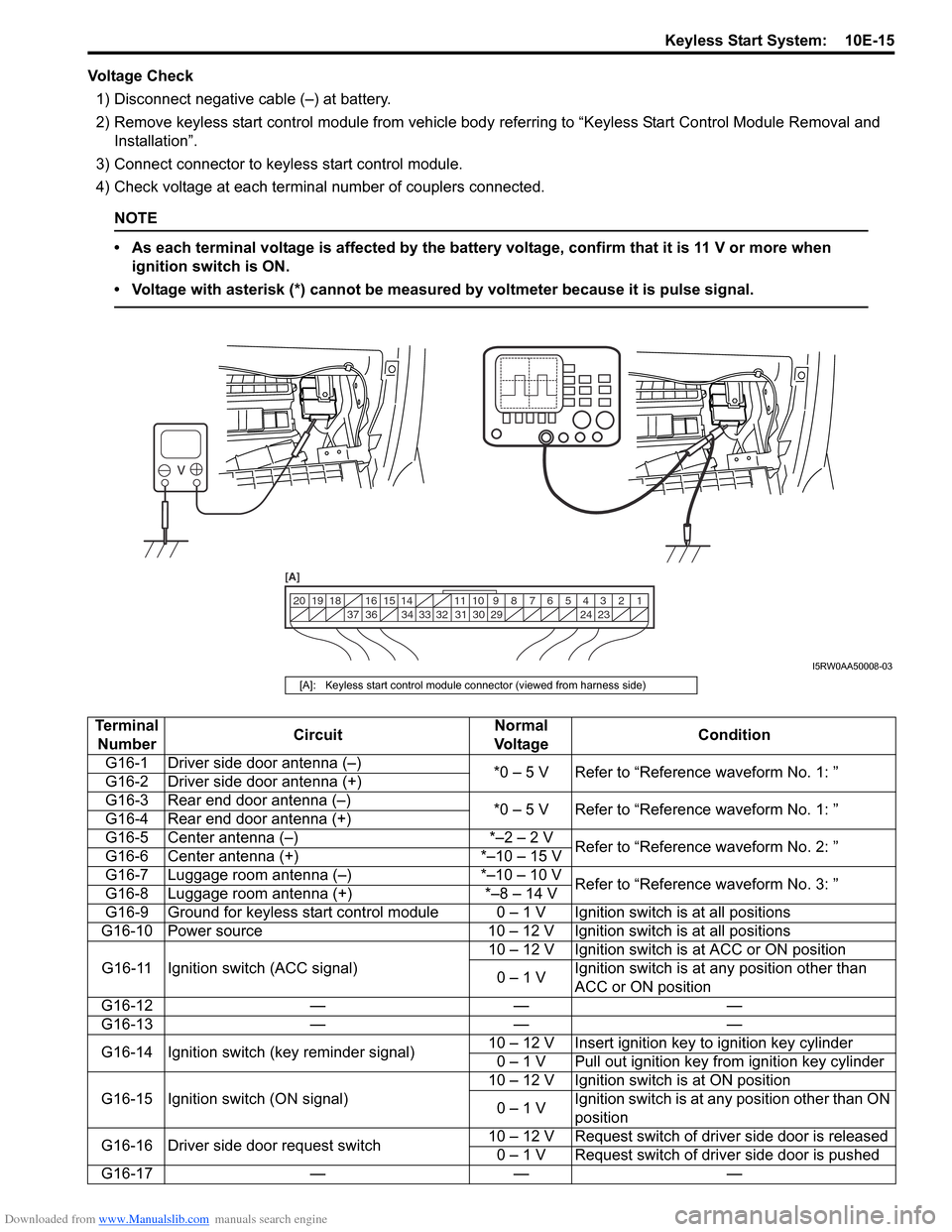
Voltage Check
1) Disconnect negative cable (–) at battery.
2) Remove keyless start control module from vehicle body referring to “Keyless Start Control Module Removal and
Installation”.
3) Connect connector to keyless start control module.
4) Check voltage at each terminal number of couplers connected.
NOTE
• As each terminal voltage is affected by the battery voltage, confirm that it is 11 V or more when
ignition switch is ON.
• Voltage with asterisk (*) cannot be measured by voltmeter because it is pulse signal.
1 2 3 4 5 6 7 8 9 10 11 14 15 16
36 34 33 32 31 30 29 24 23 37 18 19 20
[A]
I5RW0AA50008-03
[A]: Keyless start control module connector (viewed from harness side)
Terminal
NumberCircuitNormal
Vo l ta g eCondition
G16-1 Driver side door antenna (–)
*0 – 5 V Refer to “Reference waveform No. 1: ”
G16-2 Driver side door antenna (+)
G16-3 Rear end door antenna (–)
*0 – 5 V Refer to “Reference waveform No. 1: ”
G16-4 Rear end door antenna (+)
G16-5 Center antenna (–) *–2 – 2 V
Refer to “Reference waveform No. 2: ”
G16-6 Center antenna (+) *–10 – 15 V
G16-7 Luggage room antenna (–) *–10 – 10 V
Refer to “Reference waveform No. 3: ”
G16-8 Luggage room antenna (+) *–8 – 14 V
G16-9 Ground for keyless start control module 0 – 1 V Ignition switch is at all positions
G16-10 Power source 10 – 12 V Ignition switch is at all positions
G16-11 Ignition switch (ACC signal)10 – 12 V Ignition switch is at ACC or ON position
0 – 1 VIgnition switch is at any position other than
ACC or ON position
G16-12 — — —
G16-13 — — —
G16-14 Ignition switch (key reminder signal)10 – 12 V Insert ignition key to ignition key cylinder
0 – 1 V Pull out ignition key from ignition key cylinder
G16-15 Ignition switch (ON signal)10 – 12 V Ignition switch is at ON position
0 – 1 VIgnition switch is at any position other than ON
position
G16-16 Driver side door request switch10 – 12 V Request switch of driver side door is released
0 – 1 V Request switch of driver side door is pushed
G16-17 — — —
Page 1553 of 1556
Downloaded from www.Manualslib.com manuals search engine Keyless Start System: 10E-31
If remote controller or keyless start control module is
replaced or additional remote controller is necessary,
register ID code(s) of remote controller.
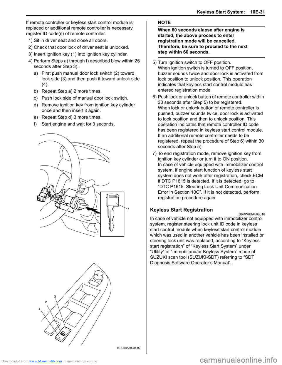
1) Sit in driver seat and close all doors.
2) Check that door lock of driver seat is unlocked.
3) Insert ignition key (1) into ignition key cylinder.
4) Perform Steps a) through f) described blow within 25
seconds after Step 3).
a) First push manual door lock switch (2) toward
lock side (3) and then push it toward unlock side
(4).
b) Repeat Step a) 2 more times.
c) Push lock side of manual door lock switch.
d) Remove ignition key from ignition key cylinder
once and then insert it again.
e) Repeat Step d) 3 more times.
f) Start engine and wait for 3 seconds.NOTE
When 60 seconds elapse after engine is
started, the above process to enter
registration mode will be cancelled.
Therefore, be sure to proceed to the next
step within 60 seconds.
5) Turn ignition switch to OFF position.
When ignition switch is turned to OFF position,
buzzer sounds twice and door lock is activated from
lock position to unlock position. This operation
indicates that keyless start control module has
entered registration mode.
6) Push lock or unlock button of remote controller within
30 seconds after Step 5) to be registered.
When lock or unlock button of remote controller is
pushed, buzzer sounds twice, door lock is activated
to lock position and then to unlock position. This
operation indicates that remote controller ID code
has been registered in keyless start control module.
If an additional remote controller needs to be
registered, repeat the procedure of Step 6) within 30
seconds after Step 5).
7) To end registration mode, remove ignition key from
ignition key cylinder or turn it to ON position.
In case of vehicle equipped with immobilizer control
system, if engine start function of keyless start
system does not work after registration, check ECM
if DTC P1615 is detected. If it is detected, go to
“DTC P1615: Steering Lock Unit Communication
Error in Section 10C”. If it is not detected, perform
registration procedure again.
Keyless Start RegistrationS6RW0DA506010
In case of vehicle not equipped with immobilizer control
system, register steering lock unit ID code in keyless
start control module when keyless start control module
which was used in another vehicle has been installed or
steering lock unit was replaced, according to “Keyless
start registration” of “Keyless Start System” under
“Utility” of “Immobi and/or Keyless System” mode of
SUZUKI scan tool (SUZUKI-SDT) referring to “SDT
Diagnosis Software Operator’s Manual”.
1
2
43
I4RS0BA50034-02