Automatic transaxle components SUZUKI SX4 2006 1.G Service User Guide
[x] Cancel search | Manufacturer: SUZUKI, Model Year: 2006, Model line: SX4, Model: SUZUKI SX4 2006 1.GPages: 1556, PDF Size: 37.31 MB
Page 750 of 1556
Downloaded from www.Manualslib.com manuals search engine 5A-102 Automatic Transmission/Transaxle:
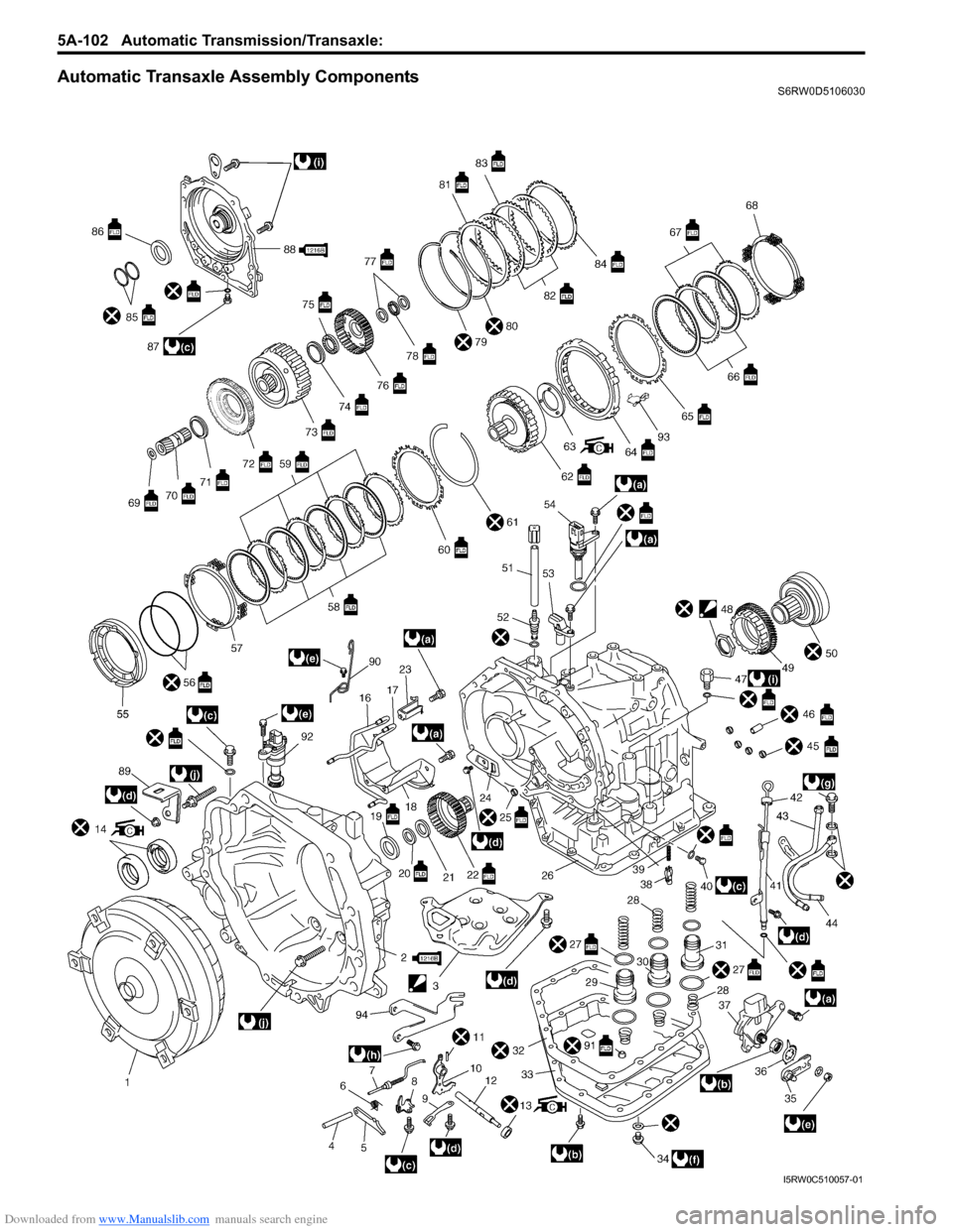
Automatic Transaxle Assembly ComponentsS6RW0D5106030
I5RW0C510057-01
Page 764 of 1556
Downloaded from www.Manualslib.com manuals search engine 5A-116 Automatic Transmission/Transaxle:
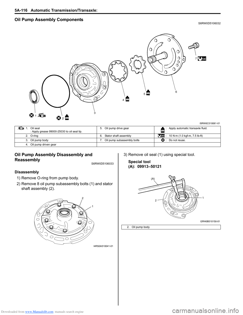
Oil Pump Assembly ComponentsS6RW0D5106032
Oil Pump Assembly Disassembly and
Reassembly
S6RW0D5106033
Disassembly
1) Remove O-ring from pump body.
2) Remove 8 oil pump subassembly bolts (1) and stator
shaft assembly (2).3) Remove oil seal (1) using special tool.
Special tool
(A): 09913–50121
I5RW0C510061-01
1. Oil seal
: Apply grease 99000-25030 to oil seal lip.5. Oil pump drive gear : Apply automatic transaxle fluid.
2. O-ring 6. Stator shaft assembly : 10 N⋅m (1.0 kgf-m, 7.5 lb-ft)
3. Oil pump body 7. Oil pump subassembly bolts : Do not reuse.
4. Oil pump driven gear
2
1
I4RS0A510041-01
2. Oil pump body
I2RH0B510150-01
Page 767 of 1556

Downloaded from www.Manualslib.com manuals search engine Automatic Transmission/Transaxle: 5A-119
Direct Clutch Assembly ComponentsS6RW0D5106035
Direct Clutch Assembly Preliminary CheckS6RW0D5106036
Install direct clutch assembly (1) to oil pump assembly
(2) blow in air (400 – 800 kPa, 4 – 8 kg/cm2, 57 – 113
psi) through oil hole (3) of oil pump assembly with
special tool attached on upper surface of direct clutch
piston, and measure piston stroke of direct clutch.
If piston stroke exceeds specified value, disassemble,
inspect and replace inner parts.
Special tool
(A): 09900–20607
(B): 09900–20701
Direct clutch piston stroke
0.4 – 0.7 mm (0.016 – 0.027 in.)
I2RH0B510160-01
1. Input shaft front thrust bearing 6. Outer O-ring 11. Direct clutch retaining plate
2. Input shaft seal ring 7. Direct clutch return spring subassembly 12. Plate snap ring
3. Input shaft subassembly 8. Shaft snap ring : Apply automatic transaxle fluid.
4. Inner O-ring 9. Direct clutch separator plate : Do not reuse.
5. Direct clutch piston 10. Direct clutch disc
I2RH0B510161-01
Page 771 of 1556

Downloaded from www.Manualslib.com manuals search engine Automatic Transmission/Transaxle: 5A-123
Forward and Reverse Clutch Assembly ComponentsS6RW0D5106039
Forward and Reverse Clutch Assembly
Preliminary Check
S6RW0D5106040
1) Install forward and reverse clutch assembly (1) to
transaxle rear cover (2), blow in compressed air (400
– 800 kPa, 4 – 8 kg/cm
2, 57 – 113 psi) through oil
hole (4) of transaxle rear cover with the special tool
attached on the upper surface of reverse clutch
retaining plate (3), and measure reverse clutch
piston stroke.
If piston stroke exceeds specified value,
disassemble, inspect and replace inner parts.
Special tool
(A): 09900–20607
(B): 09900–20701Reverse clutch piston stroke
1.20 – 1.60 mm (0.047 – 0.063 in.)
I3RM0B510061-01
1. Forward clutch balancer 8. Intermediate shaft seal ring 15. Forward clutch retaining plate
2. Forward clutch return spring subassembly 9. Reverse clutch plate snap ring 16. Forward clutch disc
3. Forward clutch piston 10. Reverse clutch retaining plate 17. Forward clutch separator plate
4. Forward clutch piston O-ring 11. Reverse clutch separator plate 18. Balancer snap ring
5. Forward clutch drum 12. Reverse clutch disc : Apply automatic transaxle fluid.
6. Forward clutch drum O-ring 13. Reverse clutch cushion plate : Do not reuse.
7. Intermediate shaft subassembly 14. Forward clutch plate snap ring
I2RH0B510176-01
Page 776 of 1556
Downloaded from www.Manualslib.com manuals search engine 5A-128 Automatic Transmission/Transaxle:
Forward Clutch Piston Lip and Forward Clutch
Balancer Lip
Check each lip for wear, deformation, cut and/or
hardening. If necessary, replace.Forward Clutch Drum Lip
Check each lip for wear, deformation, cut and/or
hardening. If necessary, replace.
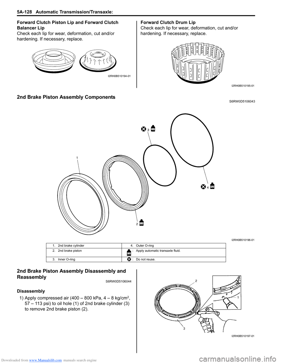
2nd Brake Piston Assembly ComponentsS6RW0D5106043
2nd Brake Piston Assembly Disassembly and
Reassembly
S6RW0D5106044
Disassembly
1) Apply compressed air (400 – 800 kPa, 4 – 8 kg/cm
2,
57 – 113 psi) to oil hole (1) of 2nd brake cylinder (3)
to remove 2nd brake piston (2).
I2RH0B510194-01
I2RH0B510195-01
I2RH0B510196-01
1. 2nd brake cylinder 4. Outer O-ring
2. 2nd brake piston : Apply automatic transaxle fluid.
3. Inner O-ring : Do not reuse.
I2RH0B510197-01
Page 777 of 1556
Downloaded from www.Manualslib.com manuals search engine Automatic Transmission/Transaxle: 5A-129
2) Remove inner O-ring (1) and outer O-ring (2).Reassembly
Reverse disassembly procedure for assembly, noting the
following points.
• Use new O-rings. Apply A/T fluid to the O-rings,
before installation.
• Install 2nd brake piston (1) to which A/T fluid is
applied to 2nd brake cylinder (2).
Do not damage O-ring when installing 2nd brake
piston.
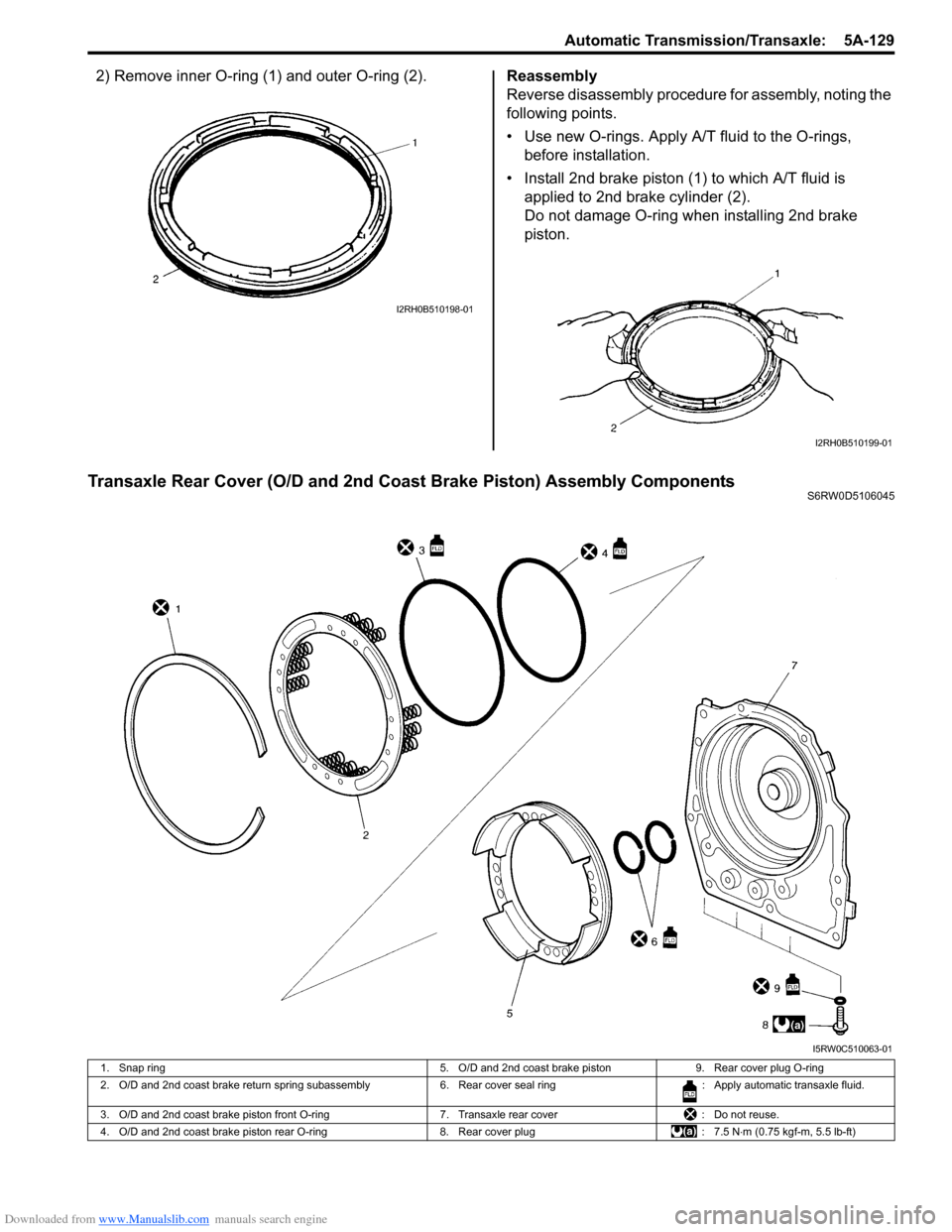
Transaxle Rear Cover (O/D and 2nd Coast Brake Piston) Assembly ComponentsS6RW0D5106045
I2RH0B510198-01
I2RH0B510199-01
I5RW0C510063-01
1. Snap ring 5. O/D and 2nd coast brake piston 9. Rear cover plug O-ring
2. O/D and 2nd coast brake return spring subassembly 6. Rear cover seal ring : Apply automatic transaxle fluid.
3. O/D and 2nd coast brake piston front O-ring 7. Transaxle rear cover : Do not reuse.
4. O/D and 2nd coast brake piston rear O-ring 8. Rear cover plug : 7.5 N⋅m (0.75 kgf-m, 5.5 lb-ft)
Page 780 of 1556
Downloaded from www.Manualslib.com manuals search engine 5A-132 Automatic Transmission/Transaxle:
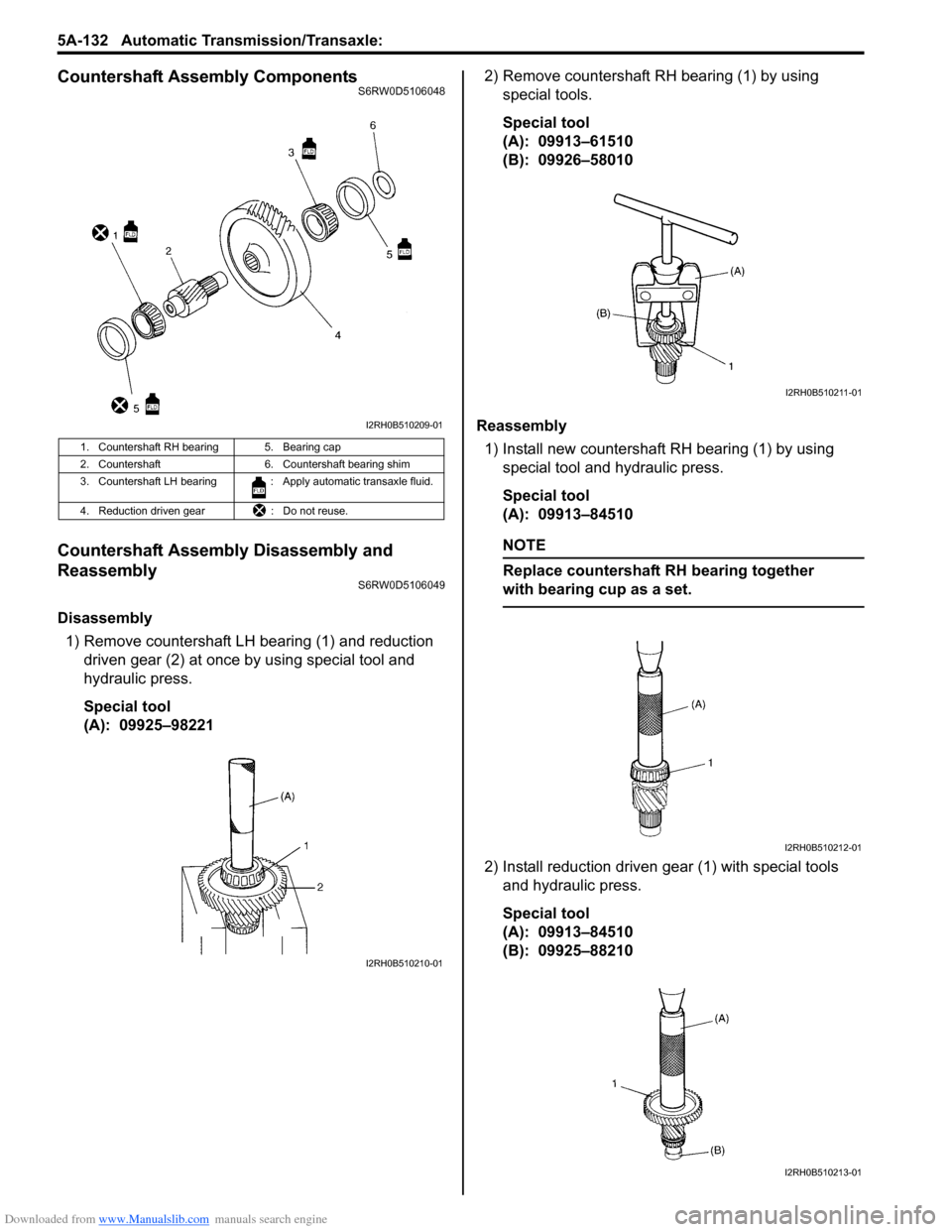
Countershaft Assembly ComponentsS6RW0D5106048
Countershaft Assembly Disassembly and
Reassembly
S6RW0D5106049
Disassembly
1) Remove countershaft LH bearing (1) and reduction
driven gear (2) at once by using special tool and
hydraulic press.
Special tool
(A): 09925–982212) Remove countershaft RH bearing (1) by using
special tools.
Special tool
(A): 09913–61510
(B): 09926–58010
Reassembly
1) Install new countershaft RH bearing (1) by using
special tool and hydraulic press.
Special tool
(A): 09913–84510
NOTE
Replace countershaft RH bearing together
with bearing cup as a set.
2) Install reduction driven gear (1) with special tools
and hydraulic press.
Special tool
(A): 09913–84510
(B): 09925–88210
1. Countershaft RH bearing 5. Bearing cap
2. Countershaft 6. Countershaft bearing shim
3. Countershaft LH bearing : Apply automatic transaxle fluid.
4. Reduction driven gear : Do not reuse.
I2RH0B510209-01
I2RH0B510210-01
I2RH0B510211-01
I2RH0B510212-01
I2RH0B510213-01
Page 781 of 1556

Downloaded from www.Manualslib.com manuals search engine Automatic Transmission/Transaxle: 5A-133
3) Install countershaft LH bearing (1) with special tools
and hydraulic press.
Special tool
(A): 09913–84510
(B): 09925–88210
Valve Body Assembly ComponentsS6RW0D5106050
I2RH0B510214-01
I4RS0A510044-01
1. Pressure control solenoid valve 6. Temperature sensor clamp : Apply automatic transaxle fluid.
2. Shift solenoid valve-A (No.1) 7. Valve body assembly : 11 N⋅m (1.1 kgf-m, 8.0 lb-ft)
3. Shift solenoid valve-B (No.2) 8. Manual valve : Do not reuse.
4. TCC pressure control solenoid valve 9. Solenoid lock plate
5. Timing solenoid valve 10. O-ring
Page 783 of 1556

Downloaded from www.Manualslib.com manuals search engine Automatic Transmission/Transaxle: 5A-135
Reassembly
Reverse disassembly procedure for assembly, noting the
following points.
• Shift solenoid valve-A and -B are identical
• After applying A/T fluid to new O-rings, fit them to
solenoid valves, then install solenoid valves to valve
body.
• Tighten solenoid valve bolts to specified torque
Tightening torque
Solenoid valve bolt (a): 11 N·m (1.1 kgf-m, 8.0 lb-ft)
Solenoid valve bolt specification
Differential Assembly ComponentsS6RW0D5106052
Bolt Length “a” Pieces
A (1) 49 mm (1.93 in.) 5
B (2) 20 mm (0.79 in.) 1
C (3) 60 mm (2.36 in.) 1
1
1 1
3
2
"a"
I4RS0A510046-01
I5RW0C510064-01
1. Differential side RH bearing 5. Side bearing shim : Apply automatic transaxle fluid.
2. Output shaft speed sensor (VSS) drive gear 6. Final gear bolt : 78 N⋅m (7.8 kgf-m, 56.5 lb-ft)
3. Differential case subassembly 7. Side bearing cup : Do not reuse.
4. Final gear 8. Differential side LH bearing
Page 808 of 1556
Downloaded from www.Manualslib.com manuals search engine 5A-160 Automatic Transmission/Transaxle:
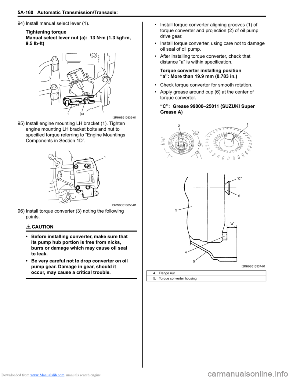
94) Install manual select lever (1).
Tightening torque
Manual select lever nut (a): 13 N·m (1.3 kgf-m,
9.5 lb-ft)
95) Install engine mounting LH bracket (1). Tighten
engine mounting LH bracket bolts and nut to
specified torque referring to “Engine Mountings
Components in Section 1D”.
96) Install torque converter (3) noting the following
points.
CAUTION!
• Before installing converter, make sure that
its pump hub portion is free from nicks,
burrs or damage which may cause oil seal
to leak.
• Be very careful not to drop converter on oil
pump gear. Damage in gear, should it
occur, may cause a critical trouble.
• Install torque converter aligning grooves (1) of
torque converter and projection (2) of oil pump
drive gear.
• Install torque converter, using care not to damage
oil seal of oil pump.
• After installing torque converter, check that
distance “a” is within specification.
Torque converter installing position
“a”: More than 19.9 mm (0.783 in.)
• Check torque converter for smooth rotation.
• Apply grease around cup (6) at the center of
torque converter.
“C”: Grease 99000–25011 (SUZUKI Super
Grease A)
1(a)I2RH0B510335-01
1
I5RW0C510058-01
4. Flange nut
5. Torque converter housing
I2RH0B510337-01