Diagrams SUZUKI SX4 2006 1.G Service User Guide
[x] Cancel search | Manufacturer: SUZUKI, Model Year: 2006, Model line: SX4, Model: SUZUKI SX4 2006 1.GPages: 1556, PDF Size: 37.31 MB
Page 944 of 1556
Downloaded from www.Manualslib.com manuals search engine 7B-4 Air Conditioning System: Manual Type
Schematic and Routing Diagram
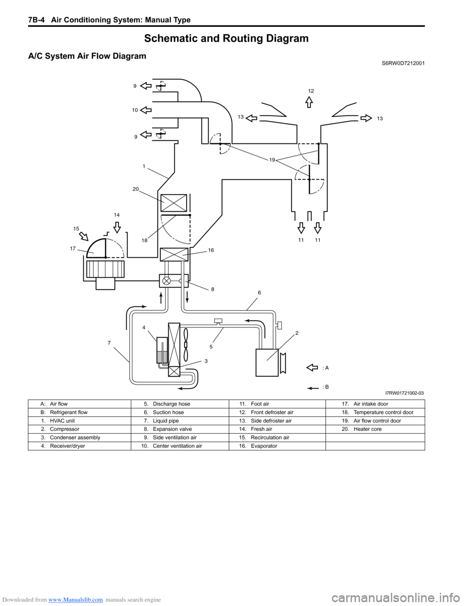
A/C System Air Flow DiagramS6RW0D7212001
1312
13 9
9 10
11 11 1514
1718
: A
: B
4
7
356
2 16
8
191
20
I7RW01721002-03
A: Air flow 5. Discharge hose 11. Foot air 17. Air intake door
B: Refrigerant flow 6. Suction hose 12. Front defroster air 18. Temperature control door
1. HVAC unit 7. Liquid pipe 13. Side defroster air 19. Air flow control door
2. Compressor 8. Expansion valve 14. Fresh air 20. Heater core
3. Condenser assembly 9. Side ventilation air 15. Recirculation air
4. Receiver/dryer 10. Center ventilation air 16. Evaporator
Page 945 of 1556
![SUZUKI SX4 2006 1.G Service User Guide Downloaded from www.Manualslib.com manuals search engine Air Conditioning System: Manual Type 7B-5
A/C System Wiring DiagramS6RW0D7212002
[A]
7
WHT
GRN5YELBLK
3
G154-3
G154-4
G154-7
G154-8
G154-10
G15 SUZUKI SX4 2006 1.G Service User Guide Downloaded from www.Manualslib.com manuals search engine Air Conditioning System: Manual Type 7B-5
A/C System Wiring DiagramS6RW0D7212002
[A]
7
WHT
GRN5YELBLK
3
G154-3
G154-4
G154-7
G154-8
G154-10
G15](/img/20/7612/w960_7612-944.png)
Downloaded from www.Manualslib.com manuals search engine Air Conditioning System: Manual Type 7B-5
A/C System Wiring DiagramS6RW0D7212002
[A]
7
WHT
GRN5YELBLK
3
G154-3
G154-4
G154-7
G154-8
G154-10
G154-13
G154-5
G154-6
G155-5
G155-2
G155-3
G155-7
G155-6
G155-1
G154-9
G154-14
BLK/WHT
YEL
BLU/WHT
RED
BRN
GRN/WHT
RED/BLK
RED
GRN
GRN/YEL
RED/YEL
RED/BLU
20
21
23 22
BLK/RED
6 2
MBLK/WHTBLK/YEL
M
11
4RED/YEL 1
E01-49
12
E01-16
GRY 13
12V
BLU/WHTE01-3510
E01-48
18
19RED/BLK
BLK/RED
BLK/RED
BRN/WHTE01-60
E01-1
E01-29BLK/WHT
M
BLU/YELBLK/YEL
5V5V 5V
WHT/BLK
9
ORN
14E01-36
C01-12C01-14GRY/REDRED/BLU
E01-41
RED/BLK
RED
WHT
8
BLK
BLK/ORN
BLU IG1
IG2
5V
17
28
29
31
2726 2524
16
16
30
34
33E01-4 E01-19WHTRED
C01-50C01-49WHTRED
32
LT GRN
C01-57
C01-2415
GRY/BLU5V
I6RW0C721002-01
[A]: Illumination control model 9. A/C refrigerant pressure
sensor18. Condenser cooling fan relay 27. Illumination light
1. Ignition switch 10. ECM 19. Condenser cooling fan motor 28. Rear defogger relay
2. Blower motor 11. Air intake control actuator 20. Blower speed selector 29. Rear defogger
3. HVAC control unit 12. Compressor relay 21. A/C switch 30. Main relay
4. Lighting switch 13. Compressor 22. Air intake selector 31. Tail light
5. Blower motor relay 14. Evaporator temperature
sensor23. Rear defogger switch 32. TCM
6. Blower motor resistor 15. ECT sensor 24. “A/C” indicator light 33. To other control module and DLC
7. Junction block assembly 16. To BCM 25. “REC” indicator light 34. ABS control module
8. BCM 17. Main fuse box 26. Rear defogger indicator
Page 981 of 1556
Downloaded from www.Manualslib.com manuals search engine Air Conditioning System: Automatic Type 7B-41
On-Board Diagnostic System DescriptionS6RW0D7221004
NOTE
The diagnostic information as diagnostic
trouble code (DTC) can be known by using
SUZUKI scan tool. For further details, refer to
“DTC Check”.
HVAC control module detects malfunctions, which may
occur in the following area.
• Inside air temperature sensor
• Evaporator temperature sensor
• Sunload sensor
• Temperature control actuator
• Air flow control actuator
• Temperature selector of HVAC control module
• Air flow selector of HVAC control module
• Blower speed selector of HVAC control module
• Back-up power supply circuit of HAVC control module
• Serial communication line between BCM and HVAC
control module• Received data from BCM as follows
– Outside air temperature sensor signal
– ECT sensor signal
– A/C refrigerant pressure sensor signal
– VSS signal
– Engine type signal
– Combination meter spec signal
– CAN communication circuit failure signal
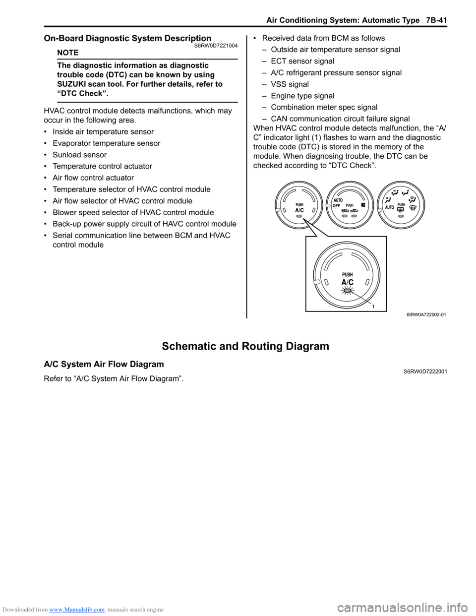
When HVAC control module detects malfunction, the “A/
C” indicator light (1) flashes to warn and the diagnostic
trouble code (DTC) is stored in the memory of the
module. When diagnosing trouble, the DTC can be
checked according to “DTC Check”.
Schematic and Routing Diagram
A/C System Air Flow DiagramS6RW0D7222001
Refer to “A/C System Air Flow Diagram”.
1
I5RW0A722002-01
Page 982 of 1556

Downloaded from www.Manualslib.com manuals search engine 7B-42 Air Conditioning System: Automatic Type
A/C System Wiring DiagramS6RW0D7222002
1913
15
16
10
11
12
5V
12V
WHT/BLU
RED
GRY/BLU
BRN/WHT
GRY/RED
BRN/YEL
PNK
BLK/ORN
RED/BLKRED/BLK
RED/BLK
14
REDWHT
WHT/RED
BLU
YEL
WHT
WHT/BLUGRNWHT
G20-18
G20-7
23 1
24
6 17
24
5V
5V
5V
5V5V
12V
12V
ORN
ORN
ORN
ORN
ORN
PNK/BLK
WHT/BLK
GRN/REDGRN
WHT
WHT
ORN
WHT
YEL
G20-10
G20-17G20-19
G20-12
G20-27
G20-24
G20-22
G20-15
G20-16
G20-28
G20-2G20-1
5V
G20
G20-26
G20-13
G20-23
BLK/RED
YEL/REDYEL/BLK
YEL
1 2 3 4 5 6 7 8 9 10 11 12 13 14
15 16 17 18 19 20 21 24 23 22 25 26 27 28 29 30
28 27
G20-9
G20-25
[A]
G20-6RED/YEL33
34 29
30 35
41
42
43
31G20-5[B]:BLK/YEL
[C]:RED/BLU
12V
3912V
40
5V
44 38
5V
3612V
12VG20-21GRN/WHT
5VG20-4GRN/YEL
5
RED/YELBRN
BLK
BLK/RED
31
5V
5V 5V
ORN
GRY
12V
BLU/WHT
LT GRN
REDWHT
RED/BLK
ORN
GRY/REDRED/BLU
BLK/RED
BLK/RED
BRN/WHT
BLK/WHT
RED
WHT
20
BLU/YEL
BLK/WHT
BLK/YEL
7
8
G20-29
BLU/RED
GRY
G20-30G20-8
BLU/YEL
9
+BB
12V
G20-3BLU
12V
BLK
5V IG1
IG2
4521
2218
26
25
32
337
[C]
[B]
I6RW0C722002-01
Page 1001 of 1556
Downloaded from www.Manualslib.com manuals search engine Air Conditioning System: Automatic Type 7B-61
DTC Troubleshooting
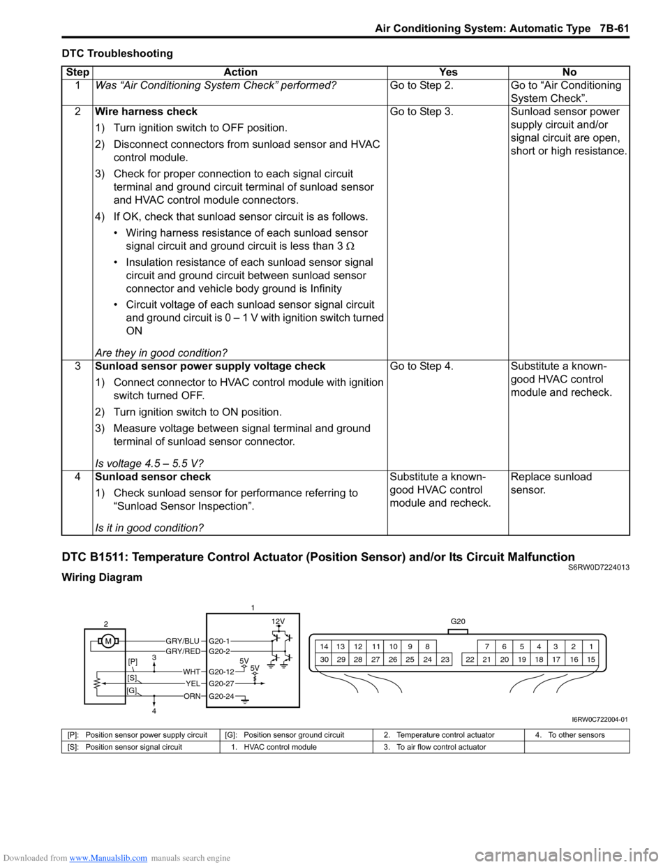
DTC B1511: Temperature Control Actuator (Position Sensor) and/or Its Circuit MalfunctionS6RW0D7224013
Wiring DiagramStep Action Yes No
1Was “Air Conditioning System Check” performed?Go to Step 2. Go to “Air Conditioning
System Check”.
2Wire harness check
1) Turn ignition switch to OFF position.
2) Disconnect connectors from sunload sensor and HVAC
control module.
3) Check for proper connection to each signal circuit
terminal and ground circuit terminal of sunload sensor
and HVAC control module connectors.
4) If OK, check that sunload sensor circuit is as follows.
• Wiring harness resistance of each sunload sensor
signal circuit and ground circuit is less than 3 Ω
• Insulation resistance of each sunload sensor signal
circuit and ground circuit between sunload sensor
connector and vehicle body ground is Infinity
• Circuit voltage of each sunload sensor signal circuit
and ground circuit is 0 – 1 V with ignition switch turned
ON
Are they in good condition?Go to Step 3. Sunload sensor power
supply circuit and/or
signal circuit are open,
short or high resistance.
3Sunload sensor power supply voltage check
1) Connect connector to HVAC control module with ignition
switch turned OFF.
2) Turn ignition switch to ON position.
3) Measure voltage between signal terminal and ground
terminal of sunload sensor connector.
Is voltage 4.5 – 5.5 V?Go to Step 4. Substitute a known-
good HVAC control
module and recheck.
4Sunload sensor check
1) Check sunload sensor for performance referring to
“Sunload Sensor Inspection”.
Is it in good condition?Substitute a known-
good HVAC control
module and recheck.Replace sunload
sensor.
G20
1 2 3 4 5 6 7 8 9 10 11 12 13 14
15 16 17 18 19 20 21 24 23 22 25 26 27 28 29 30
GRY/BLUGRY/RED
5V5V
12V
ORN
WHT
YEL
G20-12
G20-27
G20-24
G20-1G20-2
2
[P]
[S]3
4
[G]
1
I6RW0C722004-01
[P]: Position sensor power supply circuit [G]: Position sensor ground circuit 2. Temperature control actuator 4. To other sensors
[S]: Position sensor signal circuit 1. HVAC control module 3. To air flow control actuator
Page 1045 of 1556
Downloaded from www.Manualslib.com manuals search engine Air Bag System: 8B-6
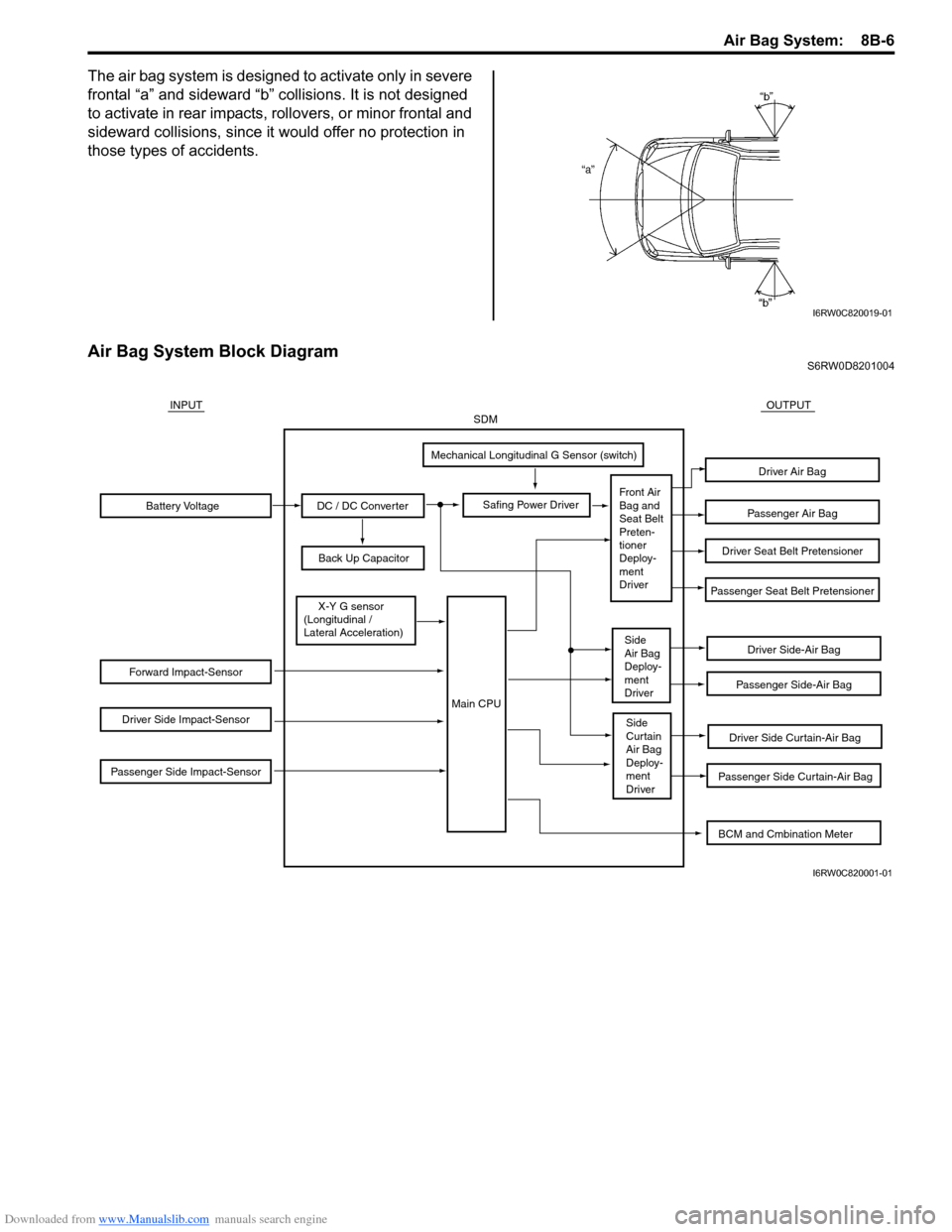
The air bag system is designed to activate only in severe
frontal “a” and sideward “b” collisions. It is not designed
to activate in rear impacts, rollovers, or minor frontal and
sideward collisions, since it would offer no protection in
those types of accidents.
Air Bag System Block DiagramS6RW0D8201004
I6RW0C820019-01
Battery Voltage
Forward Impact-Sensor
Driver Side Impact-Sensor
Passenger Side Impact-Sensor
DC / DC Converter
Back Up Capacitor
Safing Power Driver
Mechanical Longitudinal G Sensor (switch)
X-Y G sensor
(Longitudinal /
Lateral Acceleration)
Driver Side-Air Bag
Driver Side Curtain-Air Bag
Passenger Side Curtain-Air Bag
Passenger Side-Air Bag
Passenger Seat Belt Pretensioner
Driver Seat Belt Pretensioner
Passenger Air Bag
Driver Air Bag
INPUTOUTPUTSDM
Front Air
Bag and
Seat Belt
Preten-
tioner
Deploy-
ment
Driver
Side
Air Bag
Deploy-
ment
Driver
Side
Curtain
Air Bag
Deploy-
ment
Driver
Main CPU
BCM and Cmbination Meter
I6RW0C820001-01
Page 1047 of 1556
Downloaded from www.Manualslib.com manuals search engine Air Bag System: 8B-8
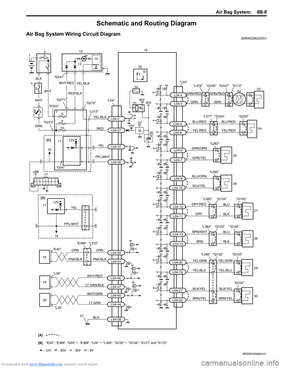
Schematic and Routing Diagram
Air Bag System Wiring Circuit DiagramS6RW0D8202001
BLK
YEL/GRN YEL/GRN
YEL/BLU YEL/BLU
WHT/RED
LT GRN/BLK
WHT/GRN
LT GRN
2223 15
29
21 19
20GRN/RED GRN/RED
GRN GRN
[A]
[B]“E40”, “E388”, “G04” “E388”, “L04” “L395”, “Q102” “Q134”, “S121” and “S172”
L04-4
L04-3
“L395” “Q132” “Q103”
L04-28 L04-46
L04-47
L04-45
L04-44 “L36”“G347” “S172” “L378” “G345”
“L35”ORN
18L04-50
L04-51 “E40”
“Q134” “Q105” “L385”
L04-12
L04-11
GRY/RED
GRY
BLK BLU
27
PNK/BLK ORN
PNK/BLK
BLU/RED
YEL/REDBLU/RED
YEL/RED
“L377” “G344” “G259”
24L04-5
L04-6
GRN/ORN
GRN/YEL
BLU/ORN
BLU/YEL
L04-9
L04-7
L04-8
25
26 “L283”
L04-10
“L285”
L04-20
L04-19“Q104” “Q133” “L384”
L04-13
L04-14BLK BLU BRN/WHT
BRN28
BLK/YEL
BRN/YELBLK/YEL
BRN/YEL30 “Q102”L04-21
L04-22
L04-2
L04-27
L04-37
“L04”
“L04”
“E388” “L372”
L04-32
32
31
G
33Y
X
34
: 12V : 30V : 30V : 5V
12V5V30V 30V
35RED 7
119
10“L313” “G272” “G271”
“G241”
“G273”
“G04”
YEL
1314
YEL/BLK
YEL/BLK
RED/BLK
12
12V
PPL/WHT
8
WHT/RED
WHT
WHT
GRN
12
3
3
5
4
6
BLK
“E324”
17+BB
[C]
16
[D]12V
PPL/WHTYEL11
16
I6RW0C820003-01
Page 1171 of 1556
![SUZUKI SX4 2006 1.G Service User Guide Downloaded from www.Manualslib.com manuals search engine Wiring Systems: 9A-4
How to Read Connector Layout DiagramS6RW0D9101004
[A-1]: Harness symbol and corresponding harness name
A: Battery harness SUZUKI SX4 2006 1.G Service User Guide Downloaded from www.Manualslib.com manuals search engine Wiring Systems: 9A-4
How to Read Connector Layout DiagramS6RW0D9101004
[A-1]: Harness symbol and corresponding harness name
A: Battery harness](/img/20/7612/w960_7612-1170.png)
Downloaded from www.Manualslib.com manuals search engine Wiring Systems: 9A-4
How to Read Connector Layout DiagramS6RW0D9101004
[A-1]: Harness symbol and corresponding harness name
A: Battery harness
B: A/C harness
C: Engine harness
D: Injector harness
E: Main harness, Oil pressure switch wire, Console wire
G: Instrument panel harness
J: Side door wire (Power window)
K: Interior light harness, Rear speaker wire, Roof wire
L: Floor harness, G sensor wire (Fuel pump harness)
M: Rear bumper harness
O: Rear end door harness
Q: Air bag/Pretensioner harness
R: (Fuel pump wire)
[A-2]: Connector Number
[B]: Ground point No.
12
11
[B][B]
Connector code
[A-1] [A-2]L 36
L13L15
R01 L14L12L11L10 L09 L36
R02 L24 L25 L33
L28 L20 L26 (TO O01)
{
L05
L16
L32 L19 L01 (TO G01)
L02 (TO E04)
L03 (TO E05) L42
R05 R04
L07 (TO K02)
I2RH01910901-01
Page 1176 of 1556
Downloaded from www.Manualslib.com manuals search engine 9A-9 Wiring Systems:
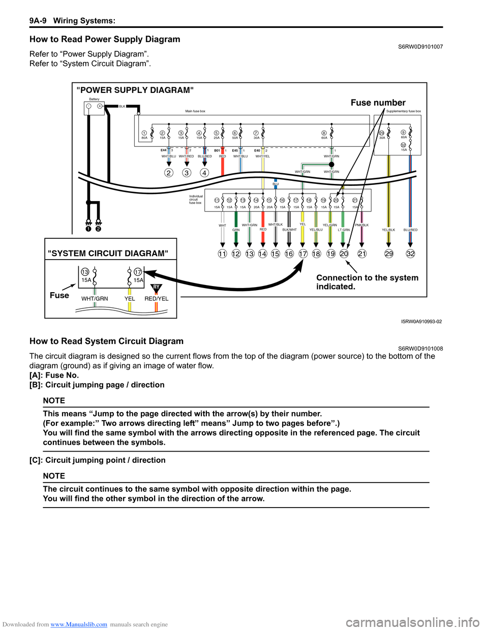
How to Read Power Supply DiagramS6RW0D9101007
Refer to “Power Supply Diagram”.
Refer to “System Circuit Diagram”.
How to Read System Circuit DiagramS6RW0D9101008
The circuit diagram is designed so the current flows from the top of the diagram (power source) to the bottom of the
diagram (ground) as if giving an image of water flow.
[A]: Fuse No.
[B]: Circuit jumping page / direction
NOTE
This means “Jump to the page directed with the arrow(s) by their number.
(For example:” Two arrows directing left” means” Jump to two pages before”.)
You will find the same symbol with the arrows directing opposite in the referenced page. The circuit
continues between the symbols.
[C]: Circuit jumping point / direction
NOTE
The circuit continues to the same symbol with opposite direction within the page.
You will find the other symbol in the direction of the arrow.
Connection to the system
indicated. "POWER SUPPLY DIAGRAM"
-+
1
Battery
80A
215A315A415A525A67850A 30A2930A3215A
960A
60A
BLK
YEL/BLKPNK/BLKLT GRNYEL/GRNYEL/BLUBLK/WHTWHT/BLKWHT/GRNREDGRNWHT
WHT/BLUWHT/REDWHT/BLUWHT/YELWHT/GRN
WHT/GRNWHT/GRN
BLU
BLU/REDRED
YELBLU/RED Individual
circuit
fuse box Main fuse boxSupplementary fuse box
11
11
243
121314151617181920212932
1213141516171819202115A 15A 15A 20A 20A 15A 15A 15A 15A 15A 15A E44321
B011E451E4021
FuseRED/YEL YEL WHT/GRN
15A
15A 1317
"SYSTEM CIRCUIT DIAGRAM"
Fuse number
12
RY
I5RW0A910993-02
Page 1178 of 1556
Downloaded from www.Manualslib.com manuals search engine 9A-11 Wiring Systems:
Connector Layout Diagram
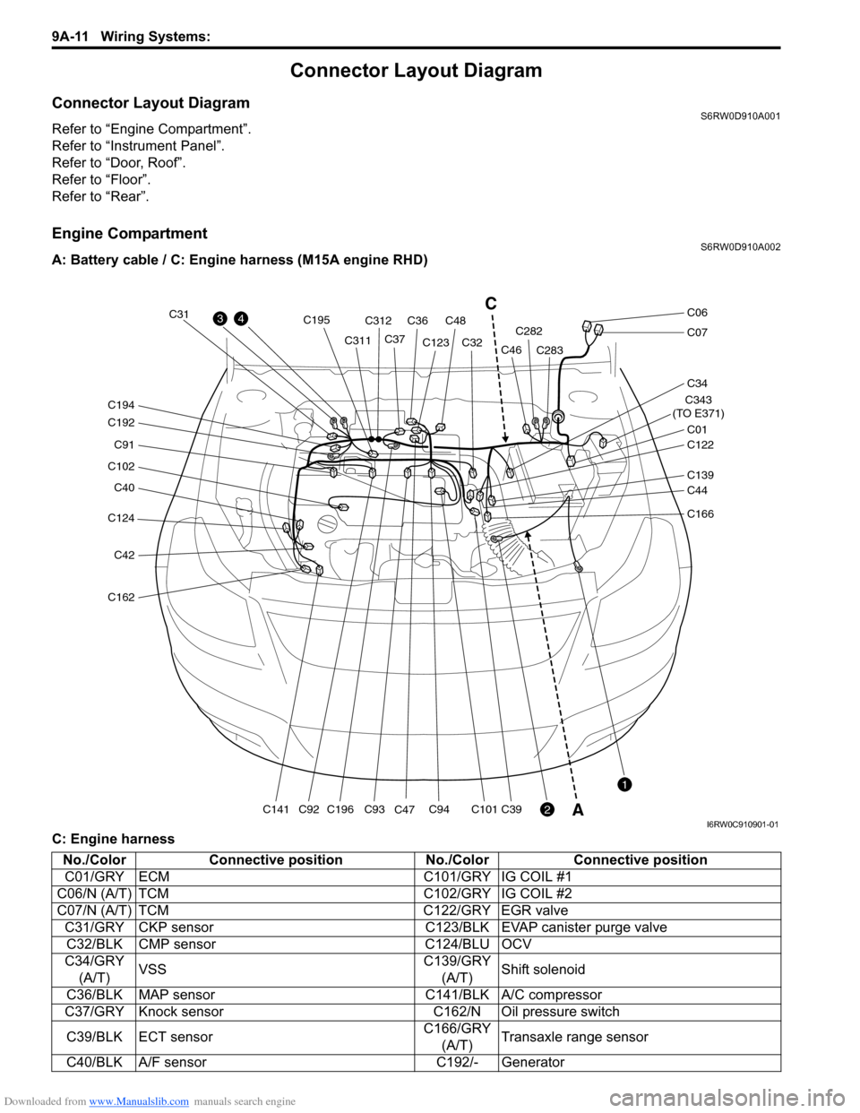
Connector Layout DiagramS6RW0D910A001
Refer to “Engine Compartment”.
Refer to “Instrument Panel”.
Refer to “Door, Roof”.
Refer to “Floor”.
Refer to “Rear”.
Engine CompartmentS6RW0D910A002
A: Battery cable / C: Engine harness (M15A engine RHD)
C: Engine harness
C124
C40
C102
C91
C192
C194
C42
C162
C141C196
C195
C93C94C101C39C92
C31
C311C312
C36C48
C37C123
C47C32C282
C283
C343
(TO E371)
C01
C34
C07
C06
C122
C46
C139
C44
C166
43
2
1
C
A
I6RW0C910901-01
No./Color Connective position No./Color Connective position
C01/GRY ECM C101/GRY IG COIL #1
C06/N (A/T) TCM C102/GRY IG COIL #2
C07/N (A/T) TCM C122/GRY EGR valve
C31/GRY CKP sensor C123/BLK EVAP canister purge valve
C32/BLK CMP sensor C124/BLU OCV
C34/GRY
(A/T)VSSC139/GRY
(A/T)Shift solenoid
C36/BLK MAP sensor C141/BLK A/C compressor
C37/GRY Knock sensor C162/N Oil pressure switch
C39/BLK ECT sensorC166/GRY
(A/T)Transaxle range sensor
C40/BLK A/F sensor C192/- Generator