Diagrams SUZUKI SX4 2006 1.G Service Owner's Manual
[x] Cancel search | Manufacturer: SUZUKI, Model Year: 2006, Model line: SX4, Model: SUZUKI SX4 2006 1.GPages: 1556, PDF Size: 37.31 MB
Page 1201 of 1556
Downloaded from www.Manualslib.com manuals search engine Wiring Systems: 9A-34
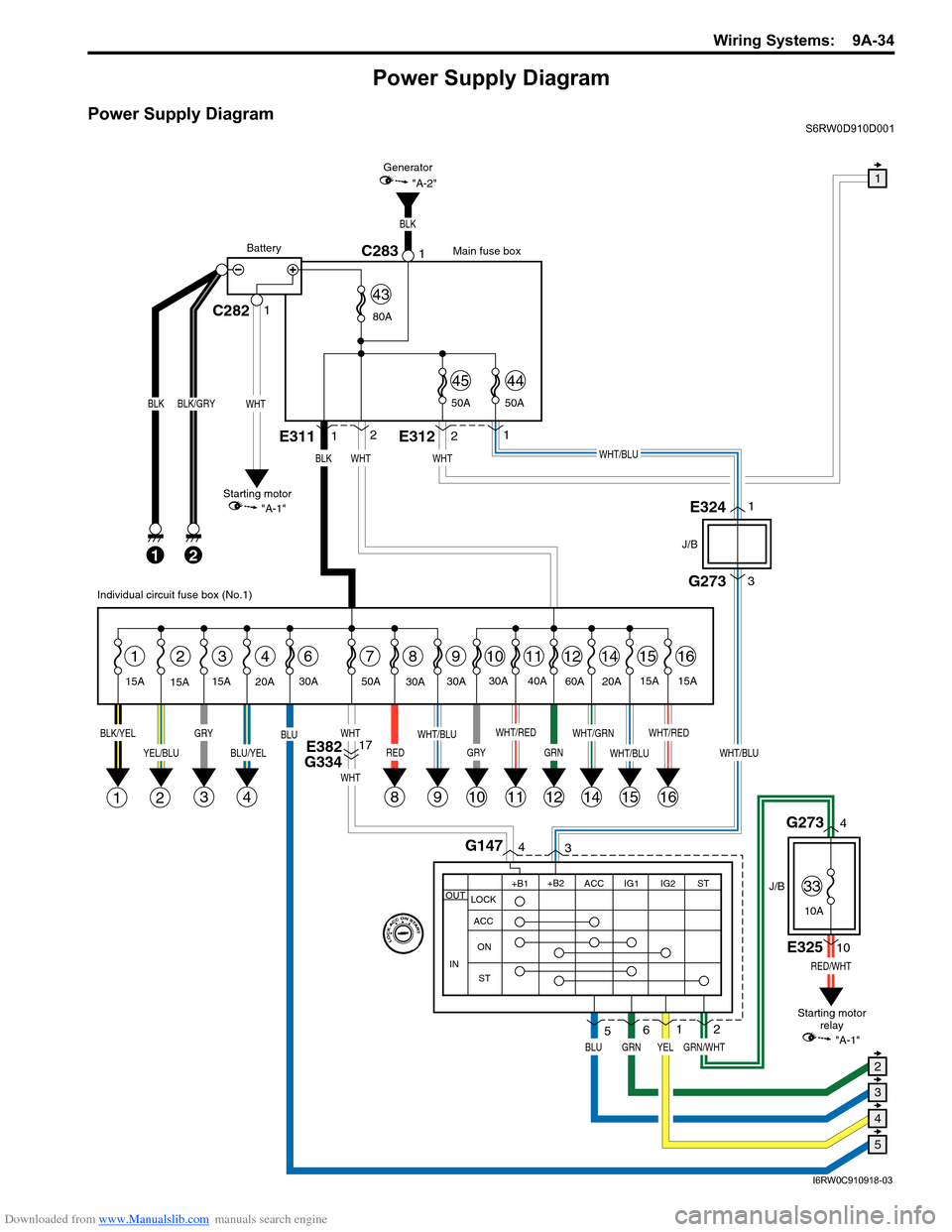
Power Supply Diagram
Power Supply DiagramS6RW0D910D001
G273
J/B
J/B
3
WHT/BLU
GRN/WHT
RED/WHT
4G1473
1
2
8
BLK
21
BLK/GRY
15A
15A15A
2314678
1E3112
WHT
1112141516
BLK/YELGRY
3
YEL/BLU
21
BLU/YEL
4
BLU
RED
WHT
WHT
WHT/RED
11
WHT/GRN
14
WHT/BLU
1516
WHT/RED
GRN
12
30A
9
WHT/BLU
9
30A
20A30A 50A40A
60A
20A15A
15A
BLK
2E3121
WHT/BLU
C282C28311
WHT
BLK
Main fuse box
Starting motor
"A-1"Generator
"A-2"
Battery
80A
50A 50A
4544
43
E3241
E32510
G2734
WHT
YEL
Individual circuit fuse box (No.1)
+B1
LOCK
ACC
ON
STACC IG1 IG2STOUT
IN
+B2
6
GRNBLU
5
Starting motor
relay
10
GRY
10
30A
E382
G33417
1
5
4
3
2
"A-1"
33
10A
I6RW0C910918-03
Page 1224 of 1556
Downloaded from www.Manualslib.com manuals search engine 9A-57 Wiring Systems:
System Circuit Diagram
System Circuit DiagramS6RW0D910E001
Refer to “A-1 Cranking System Circuit Diagram”.
Refer to “A-2 Charging System Circuit Diagram”.
Refer to “A-3 Ignition System Circuit Diagram (M15A engine, M16A engine)”.
Refer to “A-3 Ignition System Circuit Diagram (J20A engine)”.
Refer to “A-4 Cooling System Circuit Diagram (M15A engine, M16A engine)”.
Refer to “A-4 Cooling System Circuit Diagram (J20A engine)”.
Refer to “A-5 Engine and A/C Control System Circuit Diagram (M15A engine)”.
Refer to “A-5 Engine and A/C Control System Circuit Diagram (M16A engine)”.
Refer to “A-5 Engine and A/C Control System Circuit Diagram (J20A engine)”.
Refer to “A-6 A/T Control System Circuit Diagram”.
Refer to “A-7 Immobilizer System Circuit Diagram”.
Refer to “A-8 Body Control System Circuit Diagram (Except Taiwan)”.
Refer to “A-8 Body Control System Circuit Diagram (Taiwan)”.
Refer to “A-10 4WD Control System (Except Taiwan)”
Refer to “B-1 Windshield Wiper and Washer Circuit Diagram”.
Refer to “B-2 Rear Wiper and Washer Circuit Diagram (Except Taiwan)”.
Refer to “B-2 Rear Wiper and Washer Circuit Diagram (Taiwan)”.
Refer to “B-3 Rear Defogger Circuit Diagram (Except Taiwan)”.
Refer to “B-3 Rear Defogger Circuit Diagram (Taiwan)”.
Refer to “B-4 Power Window Circuit Diagram”.
Refer to “B-5 Power Door Lock Circuit Diagram (Except Taiwan)”.
Refer to “B-5 Power Door Lock Circuit Diagram (Taiwan)”.
Refer to “B-6 Power Mirror Circuit Diagram (Except Taiwan)”.
Refer to “B-6 Power Mirror Circuit Diagram (Taiwan)”.
Refer to “B-7 Horn Circuit Diagram”.
Refer to “B-8 Seat Heater Circuit Diagram”.
Refer to “B-9 Keyless Start System Circuit Diagram”
Refer to “C-1 Combination Meter Circuit Diagram (Meter)”.
Refer to “C-2 Combination Meter Circuit Diagram (Indicator)”.
Refer to “C-3 Combination Meter Circuit Diagram (Warning Light)”.
Refer to “D-1 Headlight System Circuit Diagram (Except Taiwan)”.
Refer to “D-1 Headlight System Circuit Diagram (Taiwan)”.
Refer to “D-2 Position, Tail and Licence Plate Light System Circuit Diagram (Except Taiwan)”.
Refer to “D-2 Position, Tail and Licence Plate Light System Circuit Diagram (Taiwan)”.
Refer to “D-3 Front Fog Light System Circuit Diagram (Except Taiwan)”.
Refer to “D-3 Front Fog Light System Circuit Diagram (Taiwan)”.
Refer to “D-4 Illumination Light System Circuit Diagram (Except Taiwan)”.
Refer to “D-4 Illumination Light System Circuit Diagram (Taiwan)”.
Refer to “D-5 Interior Light System Circuit Diagram (Except Taiwan)”.
Refer to “D-5 Interior Light System Circuit Diagram (Taiwan)”.
Refer to “D-6 Turn Signal and Hazard Warning Light System Circuit Diagram (Except Taiwan)”.
Refer to “D-6 Turn Signal and Hazard Warning Light System Circuit Diagram (Taiwan)”.
Refer to “D-7 Brake Light System Circuit Diagram”.
Refer to “D-8 Back-Up Light System Circuit Diagram”.
Refer to “D-9 Headlight Beam Leveling System Circuit Diagram (Manual Leveling)”.
Refer to “D-10 Rear Fog Light Circuit Diagram”.
Refer to “E-1 Heater System Circuit Diagram”.
Refer to “E-2 Auto A/C System Circuit Diagram”.
Refer to “F-1 Air-Bag System Circuit Diagram (4ch)”.
Refer to “F-1 Air-Bag System Circuit Diagram (8ch)”.
Refer to “F-2 Anti-Lock Brake System Circuit Diagram”.
Refer to “F-4 Power Steering System Circuit Diagram”.
Refer to “G-1 Audio System Circuit Diagram”.
Refer to “G-2 Multi Information Display / Accessory Socket System Circuit Diagram”.
Refer to “G-4 Navigation System Circuit Diagram”.
Page 1225 of 1556
Downloaded from www.Manualslib.com manuals search engine Wiring Systems: 9A-58
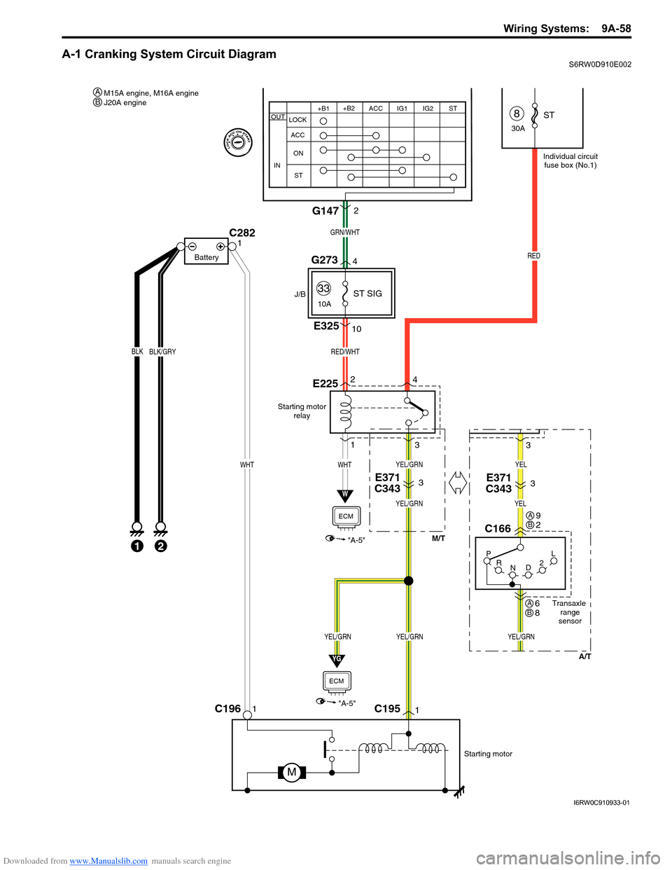
A-1 Cranking System Circuit DiagramS6RW0D910E002
Starting motor
relay
W
"A-5"
ECM
E225
C1951C1961
Starting motor
M
BLK
1
BLK/GRY
C2821
Battery
E371
C3433
RED
Individual circuit
fuse box (No.1)
8
30A
33
10A
WHTWHT
J/B
E32510
42
3 1
RED/WHT
ST
ST SIG
YEL/GRNYEL/GRN
YG
"A-5"
ECM
GRN/WHT
G1472
YEL/GRN
YEL/GRN
G2734
+B1
LOCK
ACC
ON
STACC IG1 IG2STOUT
IN
+B2
2P
R
ND2L
Transaxle
range
sensor
C166
E371
C3433
A/T M/T
3
YEL/GRN
YEL
YEL
M15A engine, M16A engine
J20A engine A
9
2AB
6
8AB
B
I6RW0C910933-01
Page 1226 of 1556
Downloaded from www.Manualslib.com manuals search engine 9A-59 Wiring Systems:
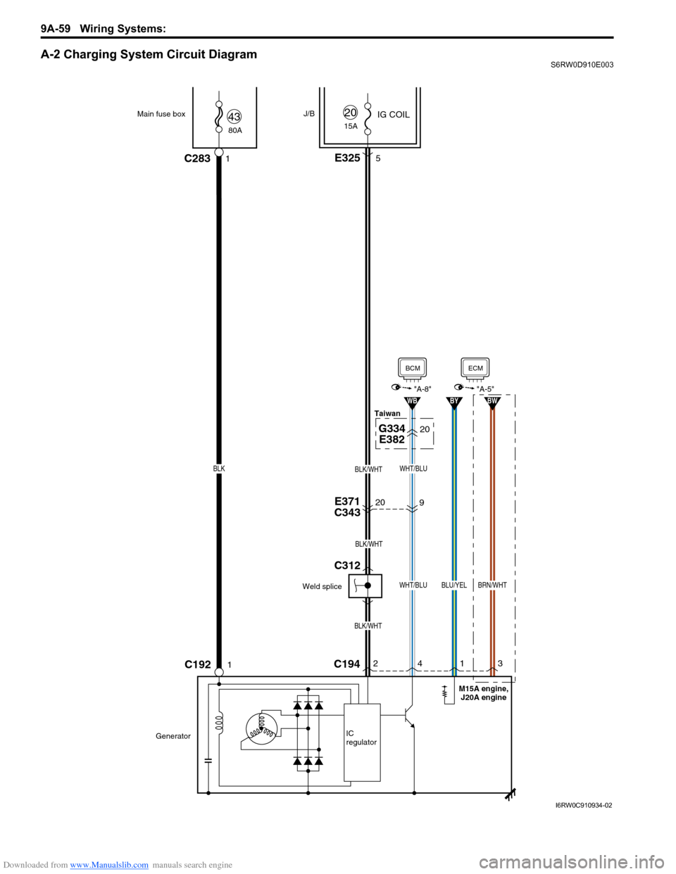
A-2 Charging System Circuit DiagramS6RW0D910E003
20E371
C343
20G334
E382
BLK/WHT
BLK/WHT
BLK/WHT
80A Main fuse box
C192
J/B
1C283
IG COIL4315A
20
GeneratorIC
regulator
1
E3255
C19424
WHT/BLU
WB
BCM
"A-8"
1
BLU/YEL
BY
3
BRN/WHT
BW
ECM
"A-5"
9
WHT/BLUBLK
Weld spliceTaiwan
M15A engine,
J20A engine
C312
I6RW0C910934-02
Page 1243 of 1556
Downloaded from www.Manualslib.com manuals search engine Wiring Systems: 9A-76
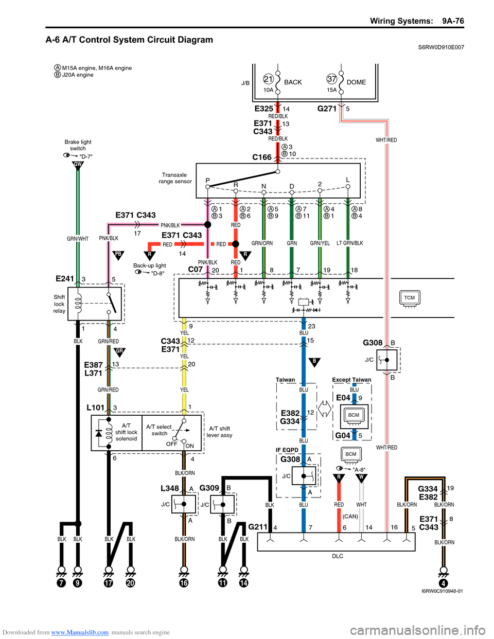
A-6 A/T Control System Circuit DiagramS6RW0D910E007
GRN/RED
Shift
lock
relay
E241
GRN/RED
C0720 8 7 19 18
E371 C343GRN/YEL
Back-up light
14
RED
"D-8"
Brake light
switch
"D-7"
R
GW
Transaxle
range sensor
TCM
L101
4
A/T select
switch A/T
shift lock
solenoidA/T shift
lever assy
BLK/ORN
16
OFF
ON
RED
1
RED
PNK/BLKRED
GRN/ORNLT GRN/BLK
C166
P
R
N
D2L
PNK/BLK
5
4
E371 C343
17
PNK/BLK
BLKBLK
63
BLK/ORN
1720
BLK
14
BLKBLK
79
L348
J/C
E387
L371C343
E3711320
BCM
BCM
DLC
G21174
BLK
BLK
11
J/C
G309
4
G334
E38219
E371
C3438
BLK/ORNBLK/ORN
5
239
GRN
RED/BLK
E371
C34313
E32514RED/BLK
GRN/WHT
10ABACK21
15ADOME37
BLK
3
1
J/B
1
A
AB
B
J/C
G308A
A
BLU
BLU
BLU
BLU
R
15YEL
YEL
YEL
12
E382
G33412
GR
PB
B
WHTRED
RW"A-8"
14
6
BLK/ORN
G2715
B
B
J/C
Taiwan
IF EQPD
BLU
Except Taiwan
G308
9E04
5G04
WHT/RED
WHT/RED
16
(CAN)
M15A engine, M16A engine
J20A engine A
8
4AB4
1AB5
9AB2
6AB1
3AB7
11AB
3
10AB
B
I6RW0C910948-01
Page 1245 of 1556
Downloaded from www.Manualslib.com manuals search engine Wiring Systems: 9A-78
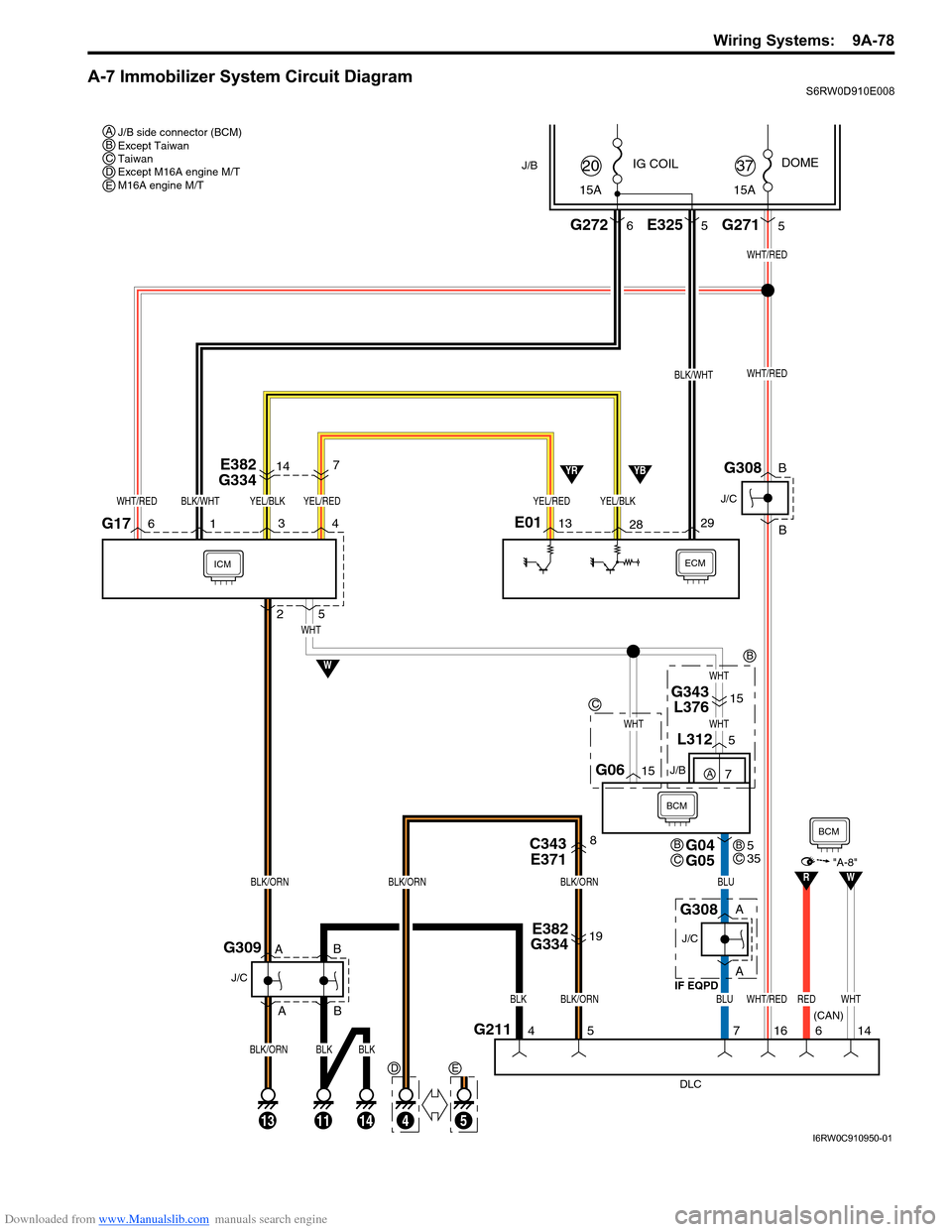
A-7 Immobilizer System Circuit DiagramS6RW0D910E008
J/B side connector (BCM)
Except Taiwan
Taiwan
Except M16A engine M/T
M16A engine M/T A
BC
DE
C
B
BCDE
ECMICM
DLC IF EQPD
G2114
J/C
G309
57
114
IG COIL
G2726
J/B
29
15A
20
BLK/WHT
13
28
YEL/BLK
YB
W
YR
E382
G33419
G343
L37615
C343
E3718
BLK/ORN
BLK/ORN
BLK/ORN
BLK
BCM
G04
G05
G0615
L3125
16
WHT/RED
WHTWHT
WHT
E013G17164
BLK/ORN
WHT
25
E382
G334714
G2715
15ADOME
37
E3255
YEL/REDYEL/BLKBLK/WHTWHT/RED
WHT/RED
WHT/RED
J/C
G308
BLU
BLU
B
B
J/C J/B
G308A
A B
B A
YEL/RED
BLK
14
BLK
13
A
BLK/ORN
REDWHT
RW"A-8"
14 6
BCM
(CAN)
5
7A
5
35BC
I6RW0C910950-01
Page 1255 of 1556
Downloaded from www.Manualslib.com manuals search engine Wiring Systems: 9A-88
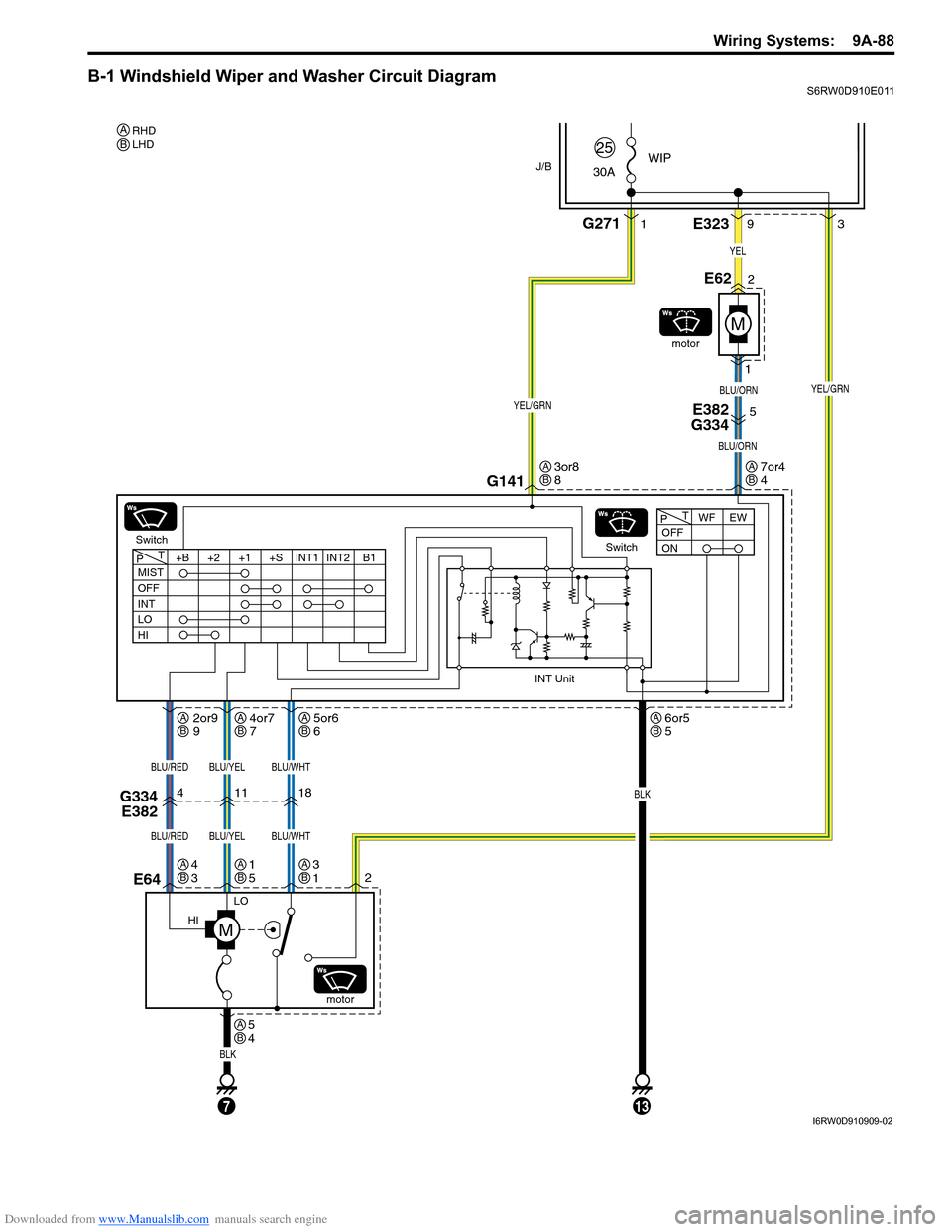
B-1 Windshield Wiper and Washer Circuit DiagramS6RW0D910E011
J/B
LO
HI
E64
BLK
E3233
9
G141
11
Switchmotor
motor
18
BLU/WHT
BLU/WHTBLU/RED
BLU/REDBLU/YEL
BLU/YEL
4
WIP
30A25
2E62
1
G2711
YEL/GRN
M
YEL/GRNBLU/ORN
137
BLK
OFF
ONWF EW
PT
MIST
OFF
INT
LO
HI+B +2 +1 +S INT1 INT2 B1
PT
INT Unit
YEL
5E382
G334
BLU/ORN
G334
E382
Switch
2
M
RHD
LHD AB
3or8
8AB
6or5
5AB5or6
6AB4or7
7AB2or9
9AB
3
1AB1
5AB
5
4AB
4
3AB
7or4
4AB
I6RW0D910909-02
Page 1260 of 1556
Downloaded from www.Manualslib.com manuals search engine 9A-93 Wiring Systems:
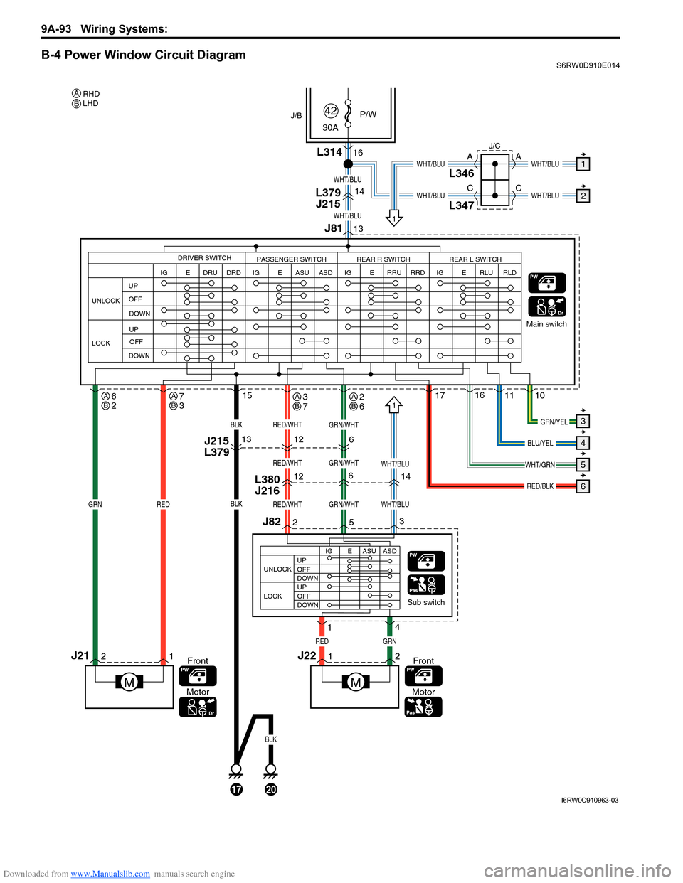
B-4 Power Window Circuit DiagramS6RW0D910E014
21
J82
L380
J216 J215
L3791212 13
6
14 616
235
1011
1716
1
4 30AP/W
42
Sub switchMain switch
J2212
GRNRED
RED
15
L314
J/B
BLK
BLK
BLK
14
13
WHT/BLU
WHT/BLU
WHT/BLU
WHT/BLU
WHT/BLU
WHT/BLU
1
2
3
4
5
6
RED/WHTWHT/BLUGRN/WHT
RED/WHTGRN/WHT
RED/WHTGRN/WHTGRN/YEL
BLU/YEL
RED/BLK
M
GRN
J21
UNLOCK
LOCKIGDRIVER SWITCH
PASSENGER SWITCH REAR R SWITCH REAR L SWITCH
E DRU DRD
IG E ASU ASDIG E RLU RLDIG E RRU RRD
WHT/GRN
L379
J215
M
UP
OFF
DOWN
UP
OFF
DOWN
J81
UNLOCKUP
OFF
DOWN
UP
OFF
DOWN LOCKIG E ASU ASD
WHT/BLU
Front
MotorFront
Motor
1
1
1720
C A
C A
J/C
L346
L347
RHD
LHD AB
6
2AB7
3AB3
7AB2
6AB
I6RW0C910963-03
Page 1268 of 1556

Downloaded from www.Manualslib.com manuals search engine 9A-101 Wiring Systems:
B-7 Horn Circuit DiagramS6RW0D910E017
33
J/B
15AHORN-HAZ
39
GRNBLU
11
Steering switch
(Horn switch) Contact
coil
H
431
220Relay
H
E281S61
E325G272
B
G346
S1711
J/B side connector (BCM)
Except Taiwan AB
BCM
A
B
I6RW0C910971-01
Page 1269 of 1556
Downloaded from www.Manualslib.com manuals search engine Wiring Systems: 9A-102
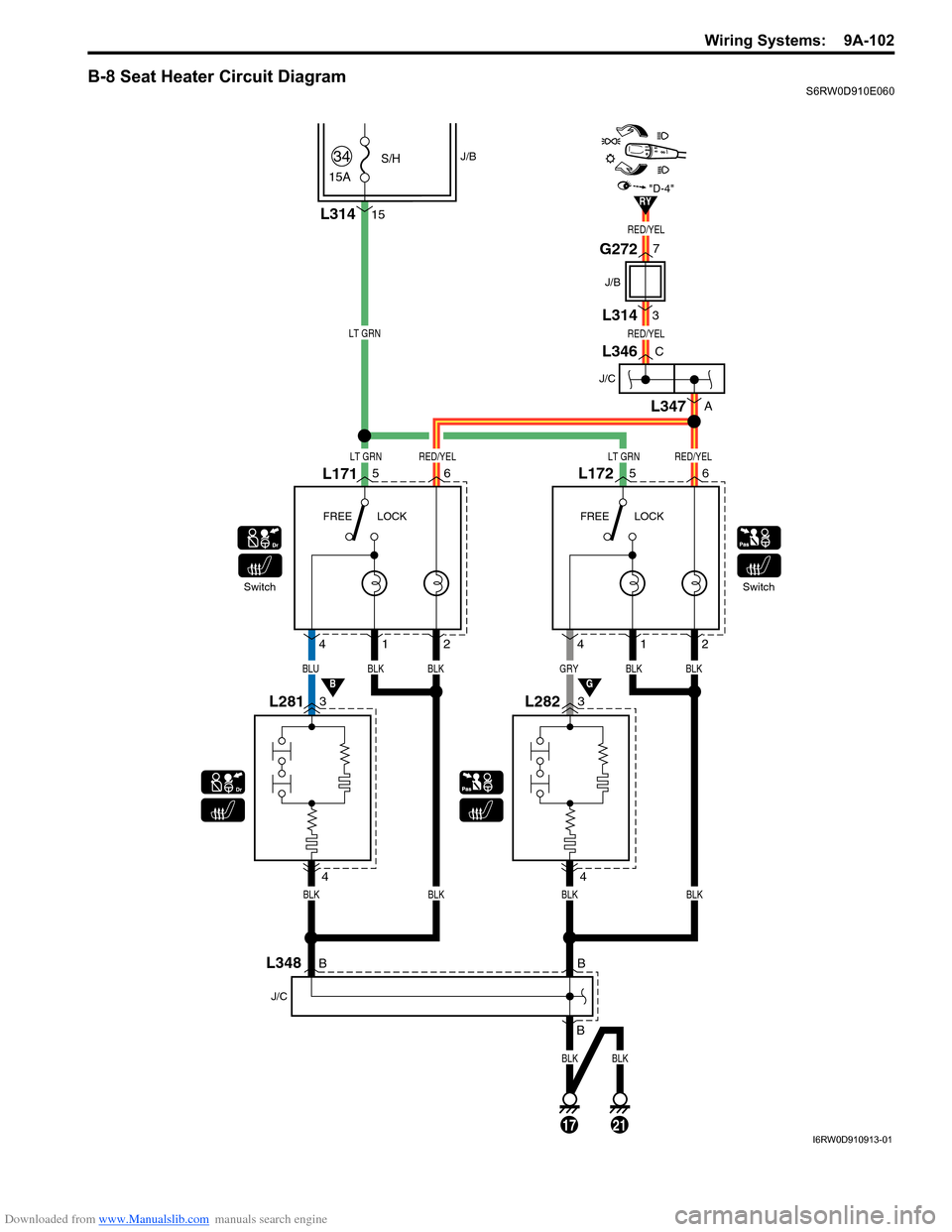
B-8 Seat Heater Circuit DiagramS6RW0D910E060
LT GRN
LT GRNLT GRNRED/YEL
RED/YEL
RED/YEL
RED/YEL
BLUBLK
L17156
L2813 4
4
12
L1725
L2823
4
BLKGRYBLK
412
BLK
BLKBLKBLKBLK
SwitchFREE LOCK FREE LOCKSwitch
L31415
15A
S/H34J/B
6
J/C
L346C
A
L347
RY
BG
"D-4"
7
3
J/B
G272
L314
B
BLK
B
B
J/C
L348
17
BLK
21I6RW0D910913-01