Engine Cooling System SUZUKI SX4 2006 1.G Service User Guide
[x] Cancel search | Manufacturer: SUZUKI, Model Year: 2006, Model line: SX4, Model: SUZUKI SX4 2006 1.GPages: 1556, PDF Size: 37.31 MB
Page 88 of 1556
Downloaded from www.Manualslib.com manuals search engine 1A-38 Engine General Information and Diagnosis:
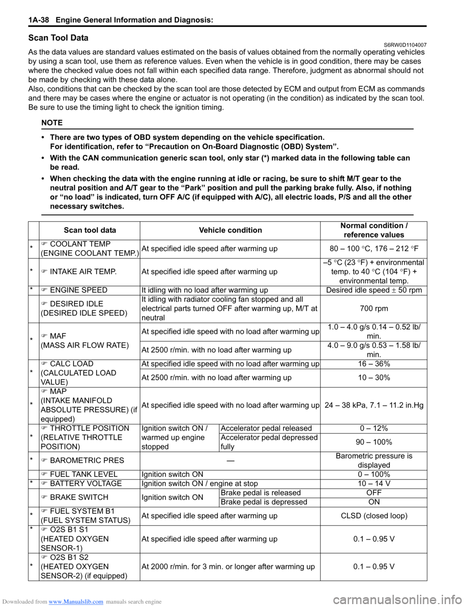
Scan Tool DataS6RW0D1104007
As the data values are standard values estimated on the basis of values obtained from the normally operating vehicles
by using a scan tool, use them as reference values. Even when the vehicle is in good condition, there may be cases
where the checked value does not fall within each specified data range. Therefore, judgment as abnormal should not
be made by checking with these data alone.
Also, conditions that can be checked by the scan tool are those detected by ECM and output from ECM as commands
and there may be cases where the engine or actuator is not operating (in the condition) as indicated by the scan tool.
Be sure to use the timing light to check the ignition timing.
NOTE
• There are two types of OBD system depending on the vehicle specification.
For identification, refer to “Precaution on On-Board Diagnostic (OBD) System”.
• With the CAN communication generic scan tool, only star (*) marked data in the following table can
be read.
• When checking the data with the engine running at idle or racing, be sure to shift M/T gear to the
neutral position and A/T gear to the “Park” position and pull the parking brake fully. Also, if nothing
or “no load” is indicated, turn OFF A/C (if equipped with A/C), all electric loads, P/S and all the other
necessary switches.
Scan tool data Vehicle conditionNormal condition /
reference values
*�) COOLANT TEMP
(ENGINE COOLANT TEMP.)At specified idle speed after warming up 80 – 100 °C, 176 – 212 °F
*�) INTAKE AIR TEMP. At specified idle speed after warming up–5 °C (23 °F) + environmental
temp. to 40 °C (104 °F) +
environmental temp.
*�) ENGINE SPEED It idling with no load after warming up Desired idle speed ± 50 rpm
�) DESIRED IDLE
(DESIRED IDLE SPEED)It idling with radiator cooling fan stopped and all
electrical parts turned OFF after warming up, M/T at
neutral700 rpm
*�) MAF
(MASS AIR FLOW RATE)At specified idle speed with no load after warming up1.0 – 4.0 g/s 0.14 – 0.52 lb/
min.
At 2500 r/min. with no load after warming up4.0 – 9.0 g/s 0.53 – 1.58 lb/
min.
*�) CALC LOAD
(CALCULATED LOAD
VA L U E )At specified idle speed with no load after warming up 16 – 36%
At 2500 r/min. with no load after warming up 10 – 30%
*�) MAP
(INTAKE MANIFOLD
ABSOLUTE PRESSURE) (if
equipped)At specified idle speed with no load after warming up 24 – 38 kPa, 7.1 – 11.2 in.Hg
*�) THROTTLE POSITION
(RELATIVE THROTTLE
POSITION)Ignition switch ON /
warmed up engine
stoppedAccelerator pedal released 0 – 12%
Accelerator pedal depressed
fully90 – 100%
*�) BAROMETRIC PRES —Barometric pressure is
displayed
�) FUEL TANK LEVEL Ignition switch ON 0 – 100%
*�) BATTERY VOLTAGE Ignition switch ON / engine at stop 10 – 14 V
�) BRAKE SWITCH Ignition switch ONBrake pedal is released OFF
Brake pedal is depressed ON
*�) FUEL SYSTEM B1
(FUEL SYSTEM STATUS)At specified idle speed after warming up CLSD (closed loop)
*�) O2S B1 S1
(HEATED OXYGEN
SENSOR-1)At specified idle speed after warming up 0.1 – 0.95 V
*�)
O2S B1 S2
(HEATED OXYGEN
SENSOR-2) (if equipped)At 2000 r/min. for 3 min. or longer after warming up 0.1 – 0.95 V
Page 97 of 1556
Downloaded from www.Manualslib.com manuals search engine Engine General Information and Diagnosis: 1A-47
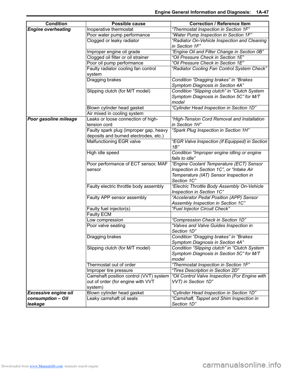
Engine overheatingInoperative thermostat“Thermostat Inspection in Section 1F”
Poor water pump performance“Water Pump Inspection in Section 1F”
Clogged or leaky radiator“Radiator On-Vehicle Inspection and Cleaning
in Section 1F”
Improper engine oil grade“Engine Oil and Filter Change in Section 0B”
Clogged oil filter or oil strainer“Oil Pressure Check in Section 1E”
Poor oil pump performance“Oil Pressure Check in Section 1E”
Faulty radiator cooling fan control
system“Radiator Cooling Fan Control System Check”
Dragging brakesCondition “Dragging brakes” in “Brakes
Symptom Diagnosis in Section 4A”
Slipping clutch (for M/T model)Condition “Slipping clutch” in “Clutch System
Symptom Diagnosis in Section 5C” for M/T
model
Blown cylinder head gasket“Cylinder Head Inspection in Section 1D”
Air mixed in cooling system
Poor gasoline mileageLeaks or loose connection of high-
tension cord“High-Tension Cord Removal and Installation
in Section 1H”
Faulty spark plug (improper gap, heavy
deposits and burned electrodes, etc.)“Spark Plug Inspection in Section 1H”
Malfunctioning EGR valve“EGR Valve Inspection (If Equipped) in Section
1B”
High idle speedCondition “Improper engine idling or engine
fails to idle”
Poor performance of ECT sensor, MAF
sensor“Engine Coolant Temperature (ECT) Sensor
Inspection in Section 1C”, or “Intake Air
Temperature (IAT) Sensor Inspection in
Section 1C”
Faulty electric throttle body assembly“Electric Throttle Body Assembly On-Vehicle
Inspection in Section 1C”
Faulty APP sensor assembly“Accelerator Pedal Position (APP) Sensor
Assembly Inspection in Section 1C”
Faulty fuel injector(s)“Fuel Injector Circuit Check”
Faulty ECM
Low compression“Compression Check in Section 1D”
Poor valve seating“Valves and Valve Guides Inspection in
Section 1D”
Dragging brakesCondition “Dragging brakes” in “Brakes
Symptom Diagnosis in Section 4A”
Slipping clutch (for M/T model)Condition “Slipping clutch” in “Clutch System
Symptom Diagnosis in Section 5C” for M/T
model
Thermostat out of order“Thermostat Inspection in Section 1F”
Improper tire pressure“Tires Description in Section 2D”
Camshaft position control (VVT) system
out of order (for engine with VVT
system)“Oil Control Valve Inspection (For Engine with
VVT) in Section 1D”
Excessive engine oil
consumption – Oil
leakageBlown cylinder head gasket“Cylinder Head Inspection in Section 1D”
Leaky camshaft oil seals“Camshaft, Tappet and Shim Inspection in
Section 1D” Condition Possible cause Correction / Reference Item
Page 180 of 1556
Downloaded from www.Manualslib.com manuals search engine 1A-130 Engine General Information and Diagnosis:
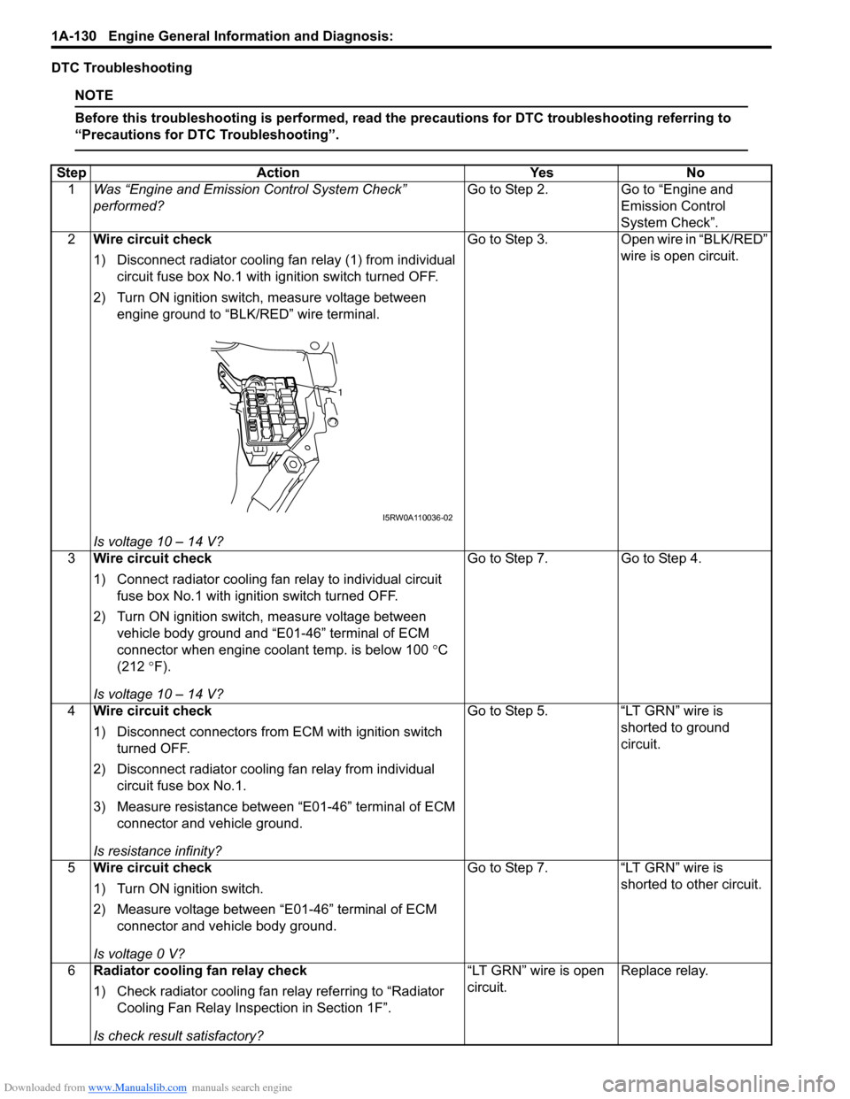
DTC Troubleshooting
NOTE
Before this troubleshooting is performed, read the precautions for DTC troubleshooting referring to
“Precautions for DTC Troubleshooting”.
Step Action Yes No
1Was “Engine and Emission Control System Check”
performed?Go to Step 2. Go to “Engine and
Emission Control
System Check”.
2Wire circuit check
1) Disconnect radiator cooling fan relay (1) from individual
circuit fuse box No.1 with ignition switch turned OFF.
2) Turn ON ignition switch, measure voltage between
engine ground to “BLK/RED” wire terminal.
Is voltage 10 – 14 V?Go to Step 3. Open wire in “BLK/RED”
wire is open circuit.
3Wire circuit check
1) Connect radiator cooling fan relay to individual circuit
fuse box No.1 with ignition switch turned OFF.
2) Turn ON ignition switch, measure voltage between
vehicle body ground and “E01-46” terminal of ECM
connector when engine coolant temp. is below 100 °C
(212 °F).
Is voltage 10 – 14 V?Go to Step 7. Go to Step 4.
4Wire circuit check
1) Disconnect connectors from ECM with ignition switch
turned OFF.
2) Disconnect radiator cooling fan relay from individual
circuit fuse box No.1.
3) Measure resistance between “E01-46” terminal of ECM
connector and vehicle ground.
Is resistance infinity?Go to Step 5. “LT GRN” wire is
shorted to ground
circuit.
5Wire circuit check
1) Turn ON ignition switch.
2) Measure voltage between “E01-46” terminal of ECM
connector and vehicle body ground.
Is voltage 0 V?Go to Step 7. “LT GRN” wire is
shorted to other circuit.
6Radiator cooling fan relay check
1) Check radiator cooling fan relay referring to “Radiator
Cooling Fan Relay Inspection in Section 1F”.
Is check result satisfactory?“LT GRN” wire is open
circuit.Replace relay.
1
I5RW0A110036-02
Page 182 of 1556
Downloaded from www.Manualslib.com manuals search engine 1A-132 Engine General Information and Diagnosis:
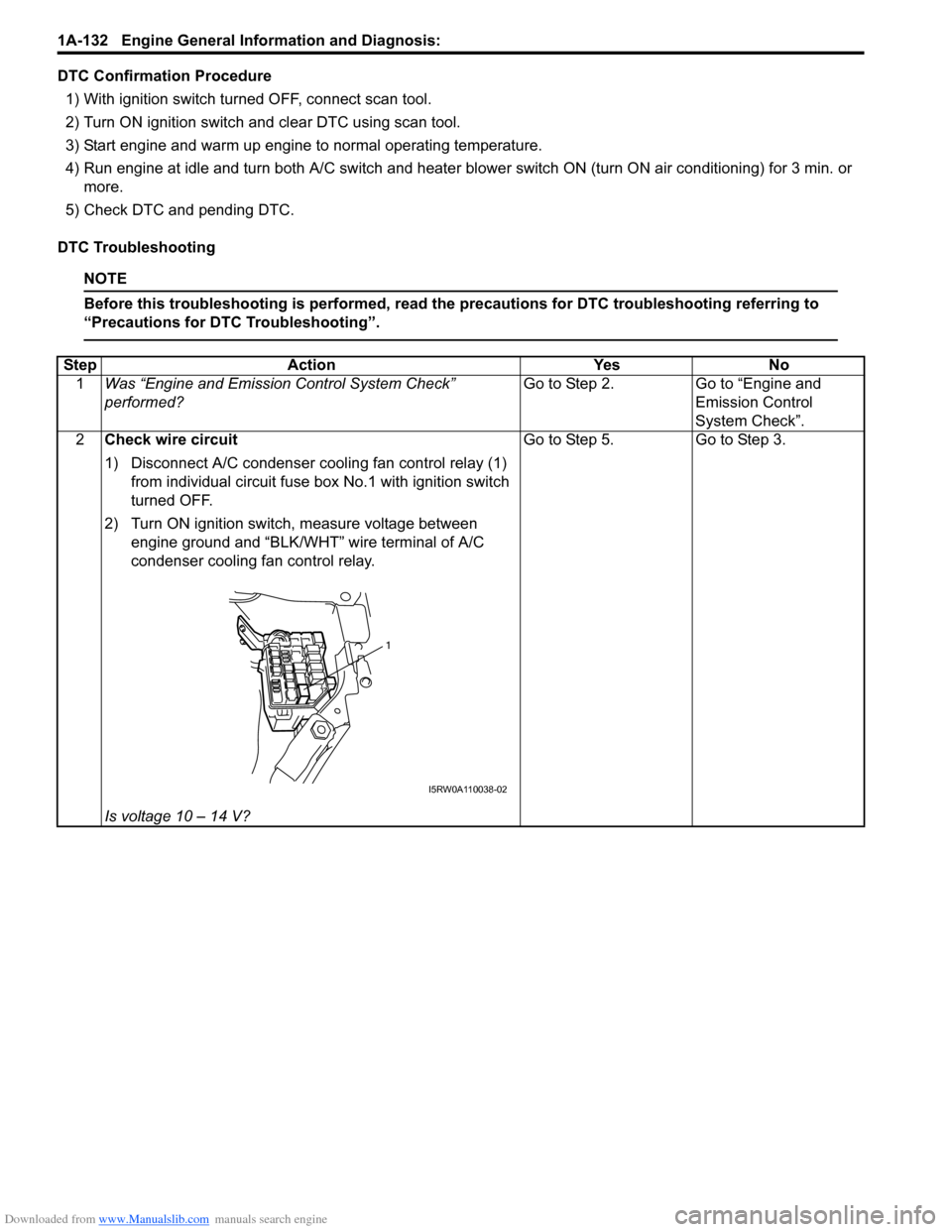
DTC Confirmation Procedure
1) With ignition switch turned OFF, connect scan tool.
2) Turn ON ignition switch and clear DTC using scan tool.
3) Start engine and warm up engine to normal operating temperature.
4) Run engine at idle and turn both A/C switch and heater blower switch ON (turn ON air conditioning) for 3 min. or
more.
5) Check DTC and pending DTC.
DTC Troubleshooting
NOTE
Before this troubleshooting is performed, read the precautions for DTC troubleshooting referring to
“Precautions for DTC Troubleshooting”.
Step Action Yes No
1Was “Engine and Emission Control System Check”
performed?Go to Step 2. Go to “Engine and
Emission Control
System Check”.
2Check wire circuit
1) Disconnect A/C condenser cooling fan control relay (1)
from individual circuit fuse box No.1 with ignition switch
turned OFF.
2) Turn ON ignition switch, measure voltage between
engine ground and “BLK/WHT” wire terminal of A/C
condenser cooling fan control relay.
Is voltage 10 – 14 V?Go to Step 5. Go to Step 3.
1
I5RW0A110038-02
Page 183 of 1556
Downloaded from www.Manualslib.com manuals search engine Engine General Information and Diagnosis: 1A-133
3Check wire circuit
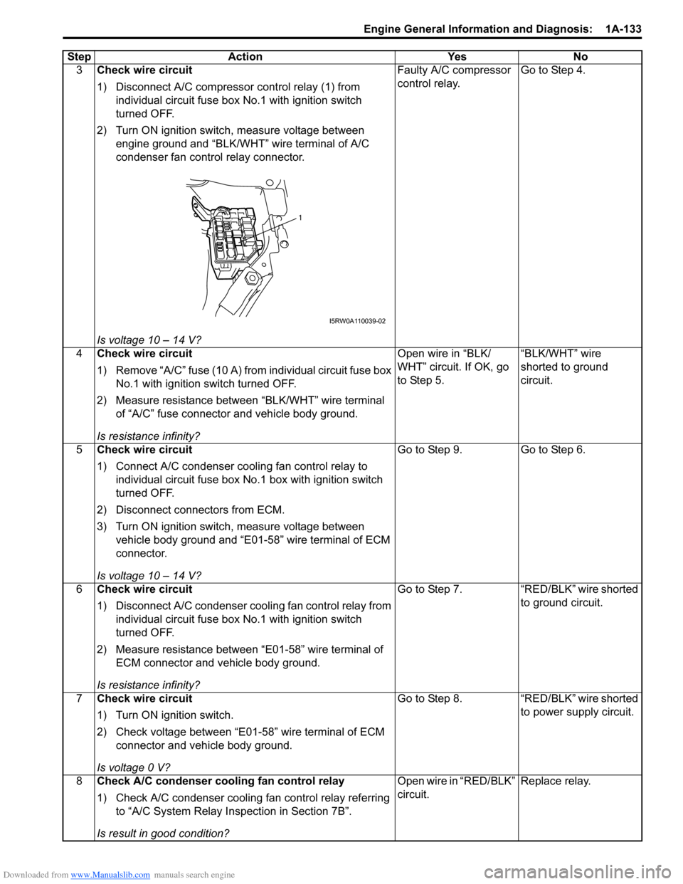
1) Disconnect A/C compressor control relay (1) from
individual circuit fuse box No.1 with ignition switch
turned OFF.
2) Turn ON ignition switch, measure voltage between
engine ground and “BLK/WHT” wire terminal of A/C
condenser fan control relay connector.
Is voltage 10 – 14 V?Faulty A/C compressor
control relay.Go to Step 4.
4Check wire circuit
1) Remove “A/C” fuse (10 A) from individual circuit fuse box
No.1 with ignition switch turned OFF.
2) Measure resistance between “BLK/WHT” wire terminal
of “A/C” fuse connector and vehicle body ground.
Is resistance infinity?Open wire in “BLK/
WHT” circuit. If OK, go
to Step 5.“BLK/WHT” wire
shorted to ground
circuit.
5Check wire circuit
1) Connect A/C condenser cooling fan control relay to
individual circuit fuse box No.1 box with ignition switch
turned OFF.
2) Disconnect connectors from ECM.
3) Turn ON ignition switch, measure voltage between
vehicle body ground and “E01-58” wire terminal of ECM
connector.
Is voltage 10 – 14 V?Go to Step 9. Go to Step 6.
6Check wire circuit
1) Disconnect A/C condenser cooling fan control relay from
individual circuit fuse box No.1 with ignition switch
turned OFF.
2) Measure resistance between “E01-58” wire terminal of
ECM connector and vehicle body ground.
Is resistance infinity?Go to Step 7. “RED/BLK” wire shorted
to ground circuit.
7Check wire circuit
1) Turn ON ignition switch.
2) Check voltage between “E01-58” wire terminal of ECM
connector and vehicle body ground.
Is voltage 0 V?Go to Step 8. “RED/BLK” wire shorted
to power supply circuit.
8Check A/C condenser cooling fan control relay
1) Check A/C condenser cooling fan control relay referring
to “A/C System Relay Inspection in Section 7B”.
Is result in good condition?Open wire in “RED/BLK”
circuit.Replace relay. Step Action Yes No
1
I5RW0A110039-02
Page 198 of 1556
Downloaded from www.Manualslib.com manuals search engine 1A-148 Engine General Information and Diagnosis:
DTC Troubleshooting
NOTE
Before this troubleshooting is performed, read the precautions for DTC troubleshooting referring to
“Precautions for DTC Troubleshooting”.
DTC P2111: Throttle Actuator Control System - Stuck OpenS6RW0D1104060
Wiring Diagram
Refer to “DTC P2101: Throttle Actuator Control Motor Circuit Range / Performance”.
DTC Detecting Condition and Trouble Area
DTC Confirmation Procedure
1) With ignition switch turned OFF, connect scan tool.
2) Turn ON ignition switch and clear DTC using scan tool.
3) Ignition switch turned OFF for 20 sec. or more.
4) Turn ON ignition switch and check DTC. Step Action Yes No
1Was “Engine and Emission Control System Check”
performed?Go to Step 2. Go to “Engine and
Emission Control
System Check”.
2Throttle actuator control relay circuit check
1) Remove throttle actuator control relay from individual
circuit fuse box No.1 with ignition switch turned OFF.
2) Check for proper connection to throttle actuator control
relay at “BLK/RED”, “GRY”, “BRN” and “GRN” wire
terminals.
3) Turn ON ignition switch.
4) Measure voltage between engine ground and “E01-32”
terminal of ECM connector.
Is voltage 0 V?Go to Step 3. “GRN” wire is shorted to
other circuit.
3Throttle actuator control relay circuit check
1) Disconnect connectors from ECM with ignition switch
turned OFF.
2) Measure resistance between engine ground and “E01-
45” terminal of ECM connector.
Is resistance infinity?Go to Step 4. “BRN” wire is shorted to
ground circuit.
4Throttle actuator control relay check
1) Check throttle actuator control relay referring to “Main
Relay, Fuel Pump Relay, Starting Motor Control Relay,
Throttle Actuator Control Relay and Radiator Cooling
Fan Relay Inspection in Section 1C”.
Is it in good condition?Substitute a known-
good ECM and recheck.Replace throttle
actuator control relay.
DTC detecting condition Trouble area
Throttle position does not change by specified value during diagnosing throttle
valve at ignition switch turned OFF.
(1 driving detection logic)• Electric throttle body assembly
•ECM
Page 242 of 1556

Downloaded from www.Manualslib.com manuals search engine 1A-192 Engine General Information and Diagnosis:
Resistance Check
1) Remove ECM from its bracket referring to “Engine Control Module (ECM) Removal and Installation in Section 1C”.
CAUTION!
Never touch terminals of ECM itself or connect voltmeter or ohmmeter (2).
2) Connect special tool to ECM connectors (1) securely.
NOTE
Do not connect the other connector of special tool to ECM.
Special tool
(A): 09933–06320
3) Check resistance between each pair of terminals of special tool connectors (1) as listed in the following table.
CAUTION!
• Be sure to connect ohmmeter probe from wire harness side of coupler.
• Be sure to turn OFF ignition switch for this check.
• Resistance in the following table represents that measured when parts temperature is 20 °C (68 °F).
1
(A)
2
3
I7RW01110032-02
Terminals Circuit Standard resistance Condition
C01-47 to E01-29 Heater of HO2S-2 4 – 15 Ω—
E01-46 to E01-1/16 Radiator cooling fan relay No.1 160 – 240 Ω—
E01-60 to E01-29 Main relay 160 – 240 ΩBattery disconnected and
ignition switch turned ON
E01-15 to E01-29 Fuel pump relay 160 – 240 Ω—
C01-16 to E01-1/16No.3 fuel injector
10.8 – 18.2 Ω—
C01-17 to E01-1/16No.4 fuel injector
C01-4 to E01-1/16EGR valve (stepping motor No.1 coil) (if
equipped)20 – 31 Ω—
C01-29 to E01-1/16 EVAP canister purge valve 28 – 35 Ω—
C01-2 to E01-1/16 No.2 fuel injector 10.8 – 18.2 Ω—
C01-3 to E01-1/16EGR valve (stepping motor No.2 coil) (if
equipped)
20 – 31 Ω— C01-18 to E01-1/16EGR valve (stepping motor No.4 coil) (if
equipped)
C01-19 to E01-1/16EGR valve (stepping motor No.3 coil) (if
equipped)
C01-46 to E01-29 Heater of HO2S-1 2 – 11 Ω—
C01-1 to E01-1/16 No.1 fuel injector 10.8 – 18.2 Ω—
E01-29 to E01-47 A/C compressor relay (if equipped with A/C) 160 – 240 Ω—
E01-58 to E01-1/16A/C condenser cooling fan relay
(if equipped with A/C)160 – 240 Ω—
C01-60 to C01-59 Oil control valve (for engine with VVT system) 6 – 15 Ω—
E01-45 to E01-1/16 Throttle actuator control relay 160 – 240 Ω—
Page 249 of 1556
Downloaded from www.Manualslib.com manuals search engine Engine General Information and Diagnosis: 1A-199
Troubleshooting
NOTE
• Before performed trouble shooting, be sure to read the “Precautions of ECM Circuit Inspection”.
• When measuring circuit voltage, resistance and/or pulse signal at ECM connector, connect the
special tool to ECM and/or the ECM connectors referring to “Inspection of ECM and Its Circuits”.
Step Action Yes No
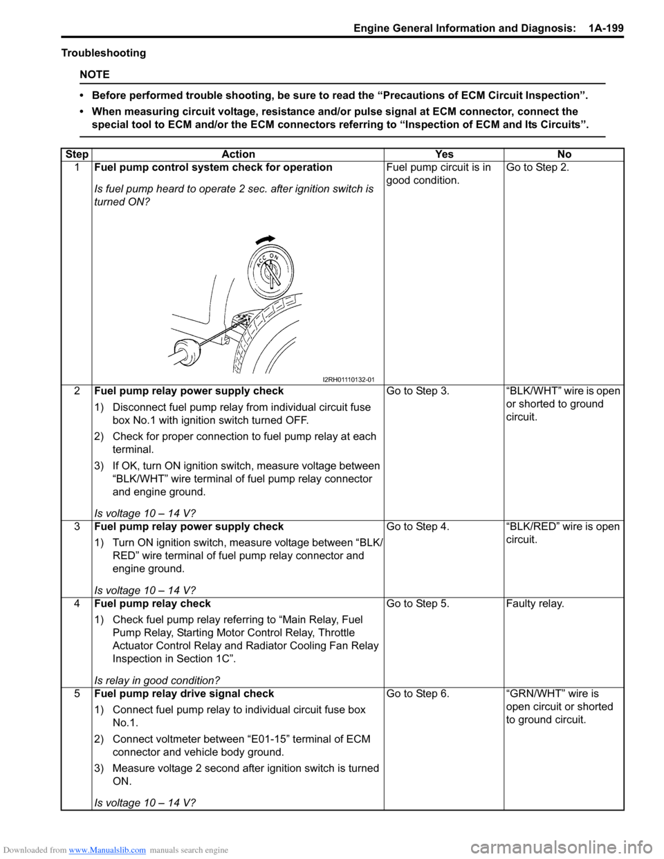
1Fuel pump control system check for operation
Is fuel pump heard to operate 2 sec. after ignition switch is
turned ON?Fuel pump circuit is in
good condition.Go to Step 2.
2Fuel pump relay power supply check
1) Disconnect fuel pump relay from individual circuit fuse
box No.1 with ignition switch turned OFF.
2) Check for proper connection to fuel pump relay at each
terminal.
3) If OK, turn ON ignition switch, measure voltage between
“BLK/WHT” wire terminal of fuel pump relay connector
and engine ground.
Is voltage 10 – 14 V?Go to Step 3. “BLK/WHT” wire is open
or shorted to ground
circuit.
3Fuel pump relay power supply check
1) Turn ON ignition switch, measure voltage between “BLK/
RED” wire terminal of fuel pump relay connector and
engine ground.
Is voltage 10 – 14 V?Go to Step 4. “BLK/RED” wire is open
circuit.
4Fuel pump relay check
1) Check fuel pump relay referring to “Main Relay, Fuel
Pump Relay, Starting Motor Control Relay, Throttle
Actuator Control Relay and Radiator Cooling Fan Relay
Inspection in Section 1C”.
Is relay in good condition?Go to Step 5. Faulty relay.
5Fuel pump relay drive signal check
1) Connect fuel pump relay to individual circuit fuse box
No.1.
2) Connect voltmeter between “E01-15” terminal of ECM
connector and vehicle body ground.
3) Measure voltage 2 second after ignition switch is turned
ON.
Is voltage 10 – 14 V?Go to Step 6. “GRN/WHT” wire is
open circuit or shorted
to ground circuit.
I2RH01110132-01
Page 252 of 1556
Downloaded from www.Manualslib.com manuals search engine 1A-202 Engine General Information and Diagnosis:
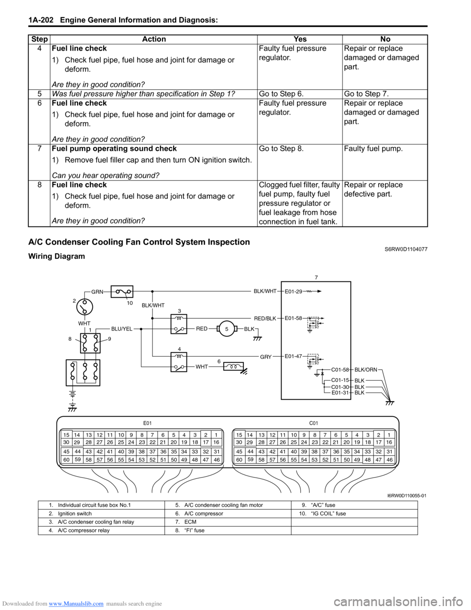
A/C Condenser Cooling Fan Control System InspectionS6RW0D1104077
Wiring Diagram4Fuel line check
1) Check fuel pipe, fuel hose and joint for damage or
deform.
Are they in good condition?Faulty fuel pressure
regulator.Repair or replace
damaged or damaged
part.
5Was fuel pressure higher than specification in Step 1?Go to Step 6. Go to Step 7.
6Fuel line check
1) Check fuel pipe, fuel hose and joint for damage or
deform.
Are they in good condition?Faulty fuel pressure
regulator.Repair or replace
damaged or damaged
part.
7Fuel pump operating sound check
1) Remove fuel filler cap and then turn ON ignition switch.
Can you hear operating sound?Go to Step 8. Faulty fuel pump.
8Fuel line check
1) Check fuel pipe, fuel hose and joint for damage or
deform.
Are they in good condition?Clogged fuel filter, faulty
fuel pump, faulty fuel
pressure regulator or
fuel leakage from hose
connection in fuel tank.Repair or replace
defective part. Step Action Yes No
E01C01
3 4
18 19 5 6 7 10 11
17 20
47 46 49 50 51 21 22
5216 259
24 14
29
55 57 54 53 59
60 582
26 27 28 15
30
56 4832 31 34 35 36 37 40 42 39 38 44
45 43 41 331 12 13
238 3 4
18 19 5 6 7 10 11
17 20
47 46 49 50 51 21 22
5216 259
24 14
29
55 57 54 53 59
60 582
26 27 28 15
30
56 4832 31 34 35 36 37 40 42 39 38 44
45 43 41 331 12 13
238
BLK/WHT
WHT
1
GRN
27
E01-29
10
89
REDBLK
3
5BLK/WHT
RED/BLKE01-58
WHT
4E01-47 GRY
BLU/YEL
6
C01-58
C01-15 C01-30
BLK/ORN
BLKBLKE01-31BLK
I6RW0D110055-01
1. Individual circuit fuse box No.1 5. A/C condenser cooling fan motor 9. “A/C” fuse
2. Ignition switch 6. A/C compressor 10. “IG COIL” fuse
3. A/C condenser cooling fan relay 7. ECM
4. A/C compressor relay 8. “FI” fuse
Page 253 of 1556
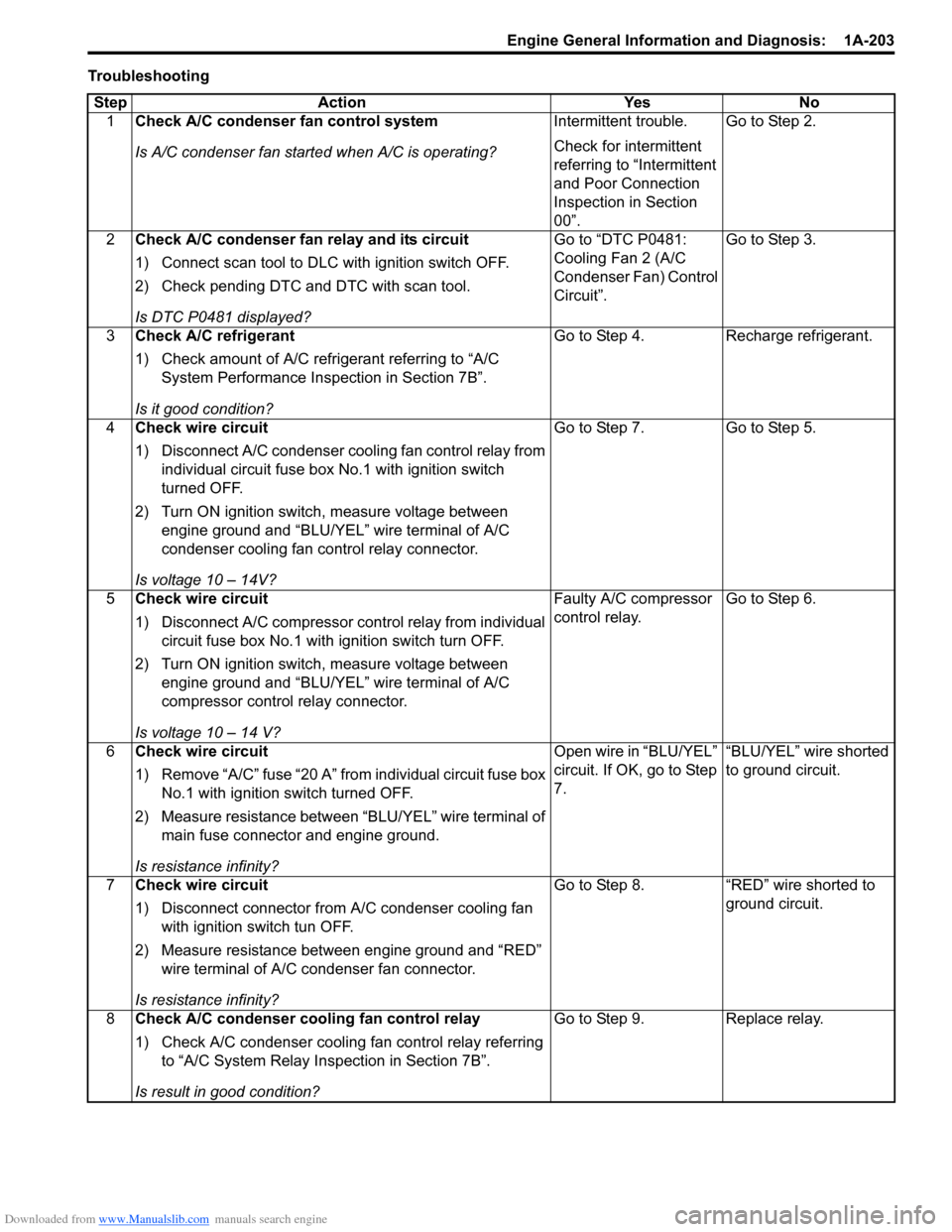
Downloaded from www.Manualslib.com manuals search engine Engine General Information and Diagnosis: 1A-203
Troubleshooting
Step Action Yes No
1Check A/C condenser fan control system
Is A/C condenser fan started when A/C is operating?Intermittent trouble.
Check for intermittent
referring to “Intermittent
and Poor Connection
Inspection in Section
00”.Go to Step 2.
2Check A/C condenser fan relay and its circuit
1) Connect scan tool to DLC with ignition switch OFF.
2) Check pending DTC and DTC with scan tool.
Is DTC P0481 displayed?Go to “DTC P0481:
Cooling Fan 2 (A/C
Condenser Fan) Control
Circuit”.Go to Step 3.
3Check A/C refrigerant
1) Check amount of A/C refrigerant referring to “A/C
System Performance Inspection in Section 7B”.
Is it good condition?Go to Step 4. Recharge refrigerant.
4Check wire circuit
1) Disconnect A/C condenser cooling fan control relay from
individual circuit fuse box No.1 with ignition switch
turned OFF.
2) Turn ON ignition switch, measure voltage between
engine ground and “BLU/YEL” wire terminal of A/C
condenser cooling fan control relay connector.
Is voltage 10 – 14V?Go to Step 7. Go to Step 5.
5Check wire circuit
1) Disconnect A/C compressor control relay from individual
circuit fuse box No.1 with ignition switch turn OFF.
2) Turn ON ignition switch, measure voltage between
engine ground and “BLU/YEL” wire terminal of A/C
compressor control relay connector.
Is voltage 10 – 14 V?Faulty A/C compressor
control relay.Go to Step 6.
6Check wire circuit
1) Remove “A/C” fuse “20 A” from individual circuit fuse box
No.1 with ignition switch turned OFF.
2) Measure resistance between “BLU/YEL” wire terminal of
main fuse connector and engine ground.
Is resistance infinity?Open wire in “BLU/YEL”
circuit. If OK, go to Step
7.“BLU/YEL” wire shorted
to ground circuit.
7Check wire circuit
1) Disconnect connector from A/C condenser cooling fan
with ignition switch tun OFF.
2) Measure resistance between engine ground and “RED”
wire terminal of A/C condenser fan connector.
Is resistance infinity?Go to Step 8. “RED” wire shorted to
ground circuit.
8Check A/C condenser cooling fan control relay
1) Check A/C condenser cooling fan control relay referring
to “A/C System Relay Inspection in Section 7B”.
Is result in good condition?Go to Step 9. Replace relay.