Air bag SUZUKI SX4 2006 1.G Service Owner's Manual
[x] Cancel search | Manufacturer: SUZUKI, Model Year: 2006, Model line: SX4, Model: SUZUKI SX4 2006 1.GPages: 1556, PDF Size: 37.31 MB
Page 871 of 1556

Downloaded from www.Manualslib.com manuals search engine Steering Wheel and Column: 6B-2
Diagnostic Information and Procedures
Checking Steering Column for Accident
Damage
S6RW0D6204001
NOTE
Vehicles involved in accidents resulting in
body damage, where steering column has
been impacted or air bag deployed may have
a damaged or misaligned steering column.
• Check that two capsules (1) are attached to steering
column bracket securely. If found loose, replace
steering column assembly.
• Take measurement “a”, “b” and “c” as follows.
If it is shorter than specified length, replace steering
column assembly or steering lower shaft with new
one.
Steering column length
“a”: 339 ± 2 mm (13.3 ± 0.08 in.)
“b”: 59.5 ± 2.1 mm (2.4 ± 0.08 in.)
Steering lower shaft length
“c”: 348 ± 1 mm (13.7 ± 0.04 in.)• Check that there is no axial looseness “d” and no
axially-vertical looseness “e” for steering column
shaft.
If found defective, replace steering column assembly
with new one.
• Check steering shaft joints and shaft for any damages
such as crack, breakage, malfunction or excessive
play.
If anything is found faulty, replace as lower shaft
assembly or steering column assembly.
• Check steering shaft for smooth rotation.
If found defective, replace as steering column
assembly.
• Check steering shaft and steering column for bend,
cracks or deformation.
If found defective, replace.
1
1
I4RS0A620001-01
“a”
“d”
“e”“b”
“c”
I7RW01620002-01
I4RS0A620003-01
Page 873 of 1556
Downloaded from www.Manualslib.com manuals search engine Steering Wheel and Column: 6B-4
Steering Wheel Removal and InstallationS6RW0D6206002
CAUTION!
Do not turn the contact coil more than
allowable number of turns (about two and a
half turns from the center position clockwise
or counterclockwise respectively) with
steering wheel removed, or coil will break.
Removal
CAUTION!
Do not hammer the end of the shaft.
Hammering it will loosen the plastic shear
pins which maintain the column length and
impair the collapsible design of the column.
1) Disconnect negative (–) cable at battery.
2) Disable air bag system referring to “Disabling Air
Bag System in Section 8B”.
3) Remove driver air bag (inflator) module from
steering wheel. Refer to “Driver Air Bag (Inflator)
Module Removal and Installation in Section 8B”.
4) Disconnect horn connector and audio control switch
connector, if equipped.
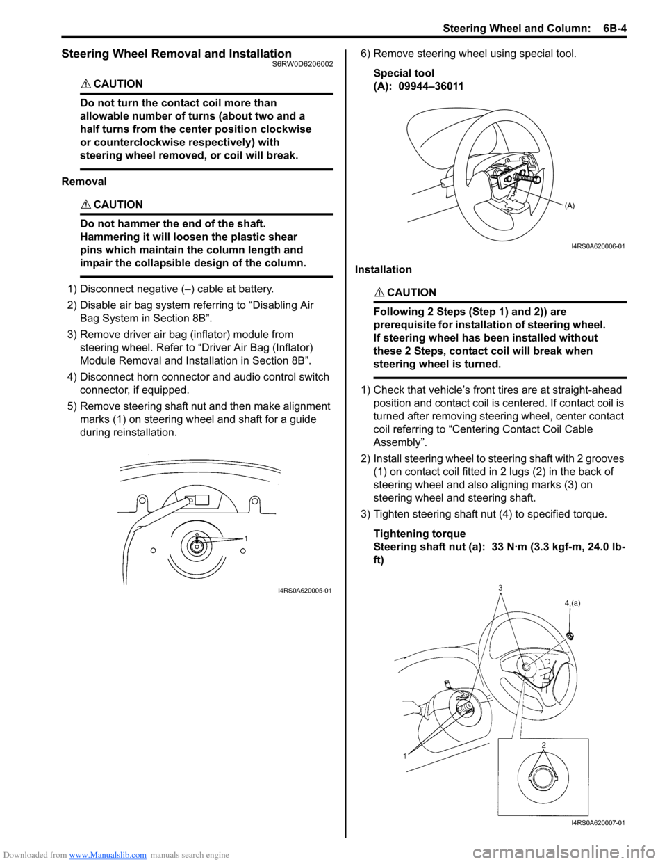
5) Remove steering shaft nut and then make alignment
marks (1) on steering wheel and shaft for a guide
during reinstallation.6) Remove steering wheel using special tool.
Special tool
(A): 09944–36011
InstallationCAUTION!
Following 2 Steps (Step 1) and 2)) are
prerequisite for installation of steering wheel.
If steering wheel has been installed without
these 2 Steps, contact coil will break when
steering wheel is turned.
1) Check that vehicle’s front tires are at straight-ahead
position and contact coil is centered. If contact coil is
turned after removing steering wheel, center contact
coil referring to “Centering Contact Coil Cable
Assembly”.
2) Install steering wheel to steering shaft with 2 grooves
(1) on contact coil fitted in 2 lugs (2) in the back of
steering wheel and also aligning marks (3) on
steering wheel and steering shaft.
3) Tighten steering shaft nut (4) to specified torque.
Tightening torque
Steering shaft nut (a): 33 N·m (3.3 kgf-m, 24.0 lb-
ft)
I4RS0A620005-01
(A)
I4RS0A620006-01
I4RS0A620007-01
Page 874 of 1556
Downloaded from www.Manualslib.com manuals search engine 6B-5 Steering Wheel and Column:
4) Connect horn connector and audio control switch
connector, if necessary.
5) Install driver air bag (inflator) module to steering
wheel. Refer to “Driver Air Bag (Inflator) Module
Removal and Installation in Section 8B”.
6) Connect negative (–) cable to battery.
7) Enable air bag system referring to “Enabling Air Bag
System in Section 8B”.
Contact Coil Cable Assembly Removal and
Installation
S6RW0D6206003
CAUTION!
Do not turn contact coil more than allowable
number of turns (about two and a half turns
from the center position clockwise or
counterclockwise respectively), or coil will
break.
Removal
1) Disconnect negative (–) cable at battery.
2) Disable air bag system referring to “Disabling Air
Bag System in Section 8B”.
3) Remove steering wheel from steering column
referring to “Steering Wheel Removal and
Installation”.
4) Remove steering column hole cover.
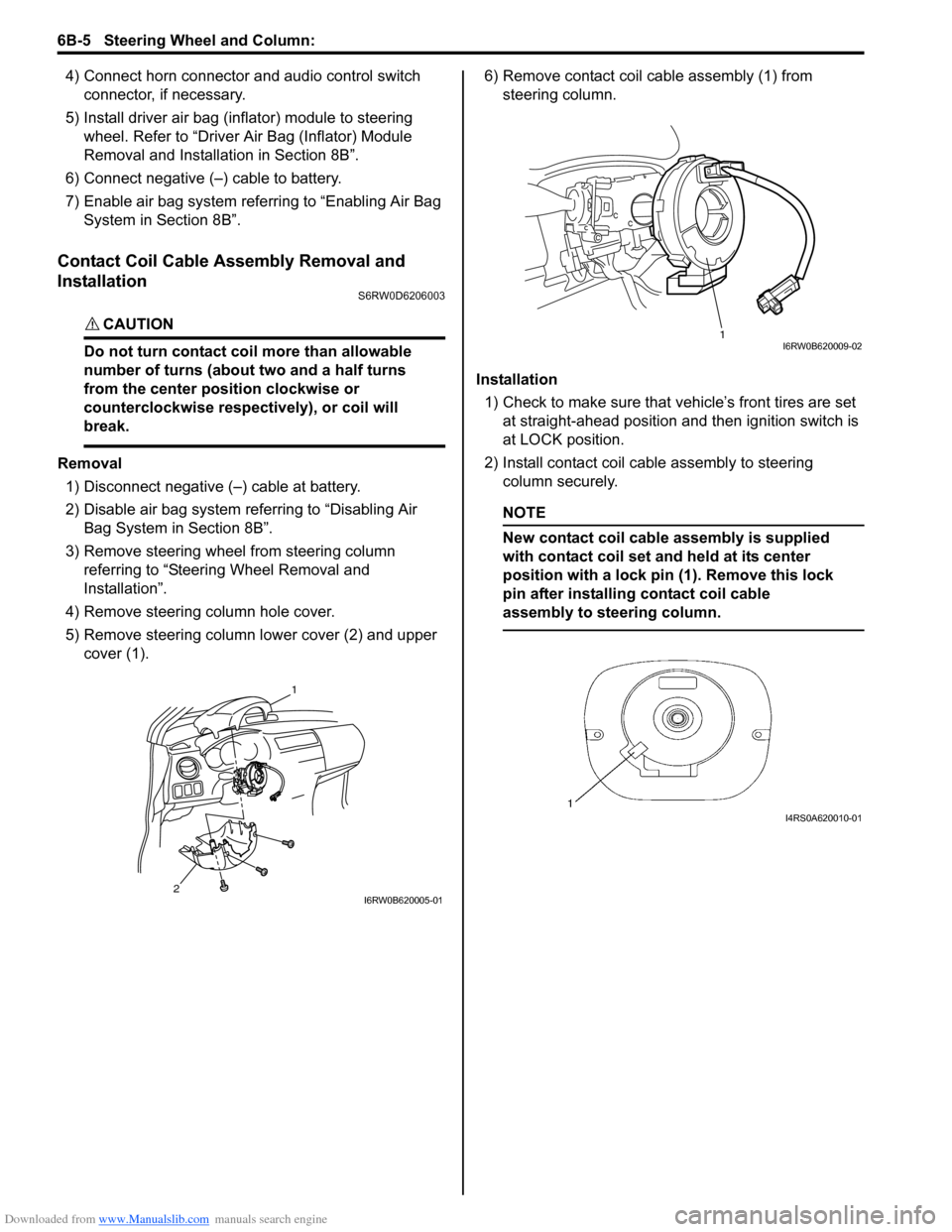
5) Remove steering column lower cover (2) and upper
cover (1).6) Remove contact coil cable assembly (1) from
steering column.
Installation
1) Check to make sure that vehicle’s front tires are set
at straight-ahead position and then ignition switch is
at LOCK position.
2) Install contact coil cable assembly to steering
column securely.
NOTE
New contact coil cable assembly is supplied
with contact coil set and held at its center
position with a lock pin (1). Remove this lock
pin after installing contact coil cable
assembly to steering column.
2
1
I6RW0B620005-01
1I6RW0B620009-02
I4RS0A620010-01
Page 875 of 1556
Downloaded from www.Manualslib.com manuals search engine Steering Wheel and Column: 6B-6
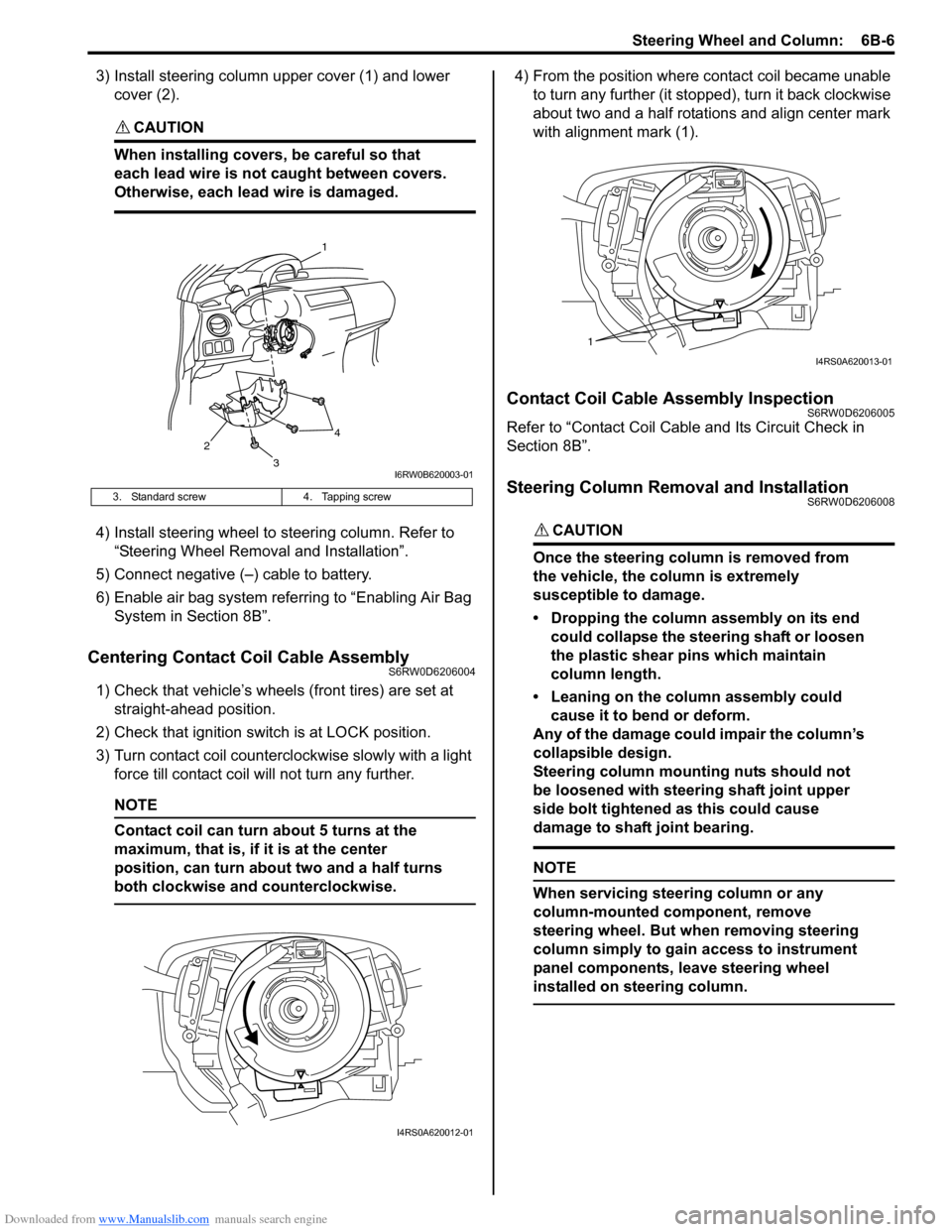
3) Install steering column upper cover (1) and lower
cover (2).
CAUTION!
When installing covers, be careful so that
each lead wire is not caught between covers.
Otherwise, each lead wire is damaged.
4) Install steering wheel to steering column. Refer to
“Steering Wheel Removal and Installation”.
5) Connect negative (–) cable to battery.
6) Enable air bag system referring to “Enabling Air Bag
System in Section 8B”.
Centering Contact Coil Cable AssemblyS6RW0D6206004
1) Check that vehicle’s wheels (front tires) are set at
straight-ahead position.
2) Check that ignition switch is at LOCK position.
3) Turn contact coil counterclockwise slowly with a light
force till contact coil will not turn any further.
NOTE
Contact coil can turn about 5 turns at the
maximum, that is, if it is at the center
position, can turn about two and a half turns
both clockwise and counterclockwise.
4) From the position where contact coil became unable
to turn any further (it stopped), turn it back clockwise
about two and a half rotations and align center mark
with alignment mark (1).
Contact Coil Cable Assembly InspectionS6RW0D6206005
Refer to “Contact Coil Cable and Its Circuit Check in
Section 8B”.
Steering Column Removal and InstallationS6RW0D6206008
CAUTION!
Once the steering column is removed from
the vehicle, the column is extremely
susceptible to damage.
• Dropping the column assembly on its end
could collapse the steering shaft or loosen
the plastic shear pins which maintain
column length.
• Leaning on the column assembly could
cause it to bend or deform.
Any of the damage could impair the column’s
collapsible design.
Steering column mounting nuts should not
be loosened with steering shaft joint upper
side bolt tightened as this could cause
damage to shaft joint bearing.
NOTE
When servicing steering column or any
column-mounted component, remove
steering wheel. But when removing steering
column simply to gain access to instrument
panel components, leave steering wheel
installed on steering column.
3. Standard screw 4. Tapping screw
2
1
3
4
I6RW0B620003-01
I4RS0A620012-01
1
I4RS0A620013-01
Page 876 of 1556
Downloaded from www.Manualslib.com manuals search engine 6B-7 Steering Wheel and Column:
Removal
WARNING!
Never rest a steering column assembly on
the steering wheel with the air bag (inflator)
module face down and column vertical.
Otherwise, personal injury may result.
1) Disconnect negative (–) cable at battery.
2) Disable air bag system. Refer to “Disabling Air Bag
System in Section 8B”.
3) Remove steering wheel and contact coil cable
assembly referring to “Steering Wheel Removal and
Installation” and “Contact Coil Cable Assembly
Removal and Installation”.
4) (Immobilizer model)
Remove immobilizer control module from steering
column, referring to “ICM Removal and Installation in
Section 10C”.
5) Detach lighting switch and wiper switch from steering
column.
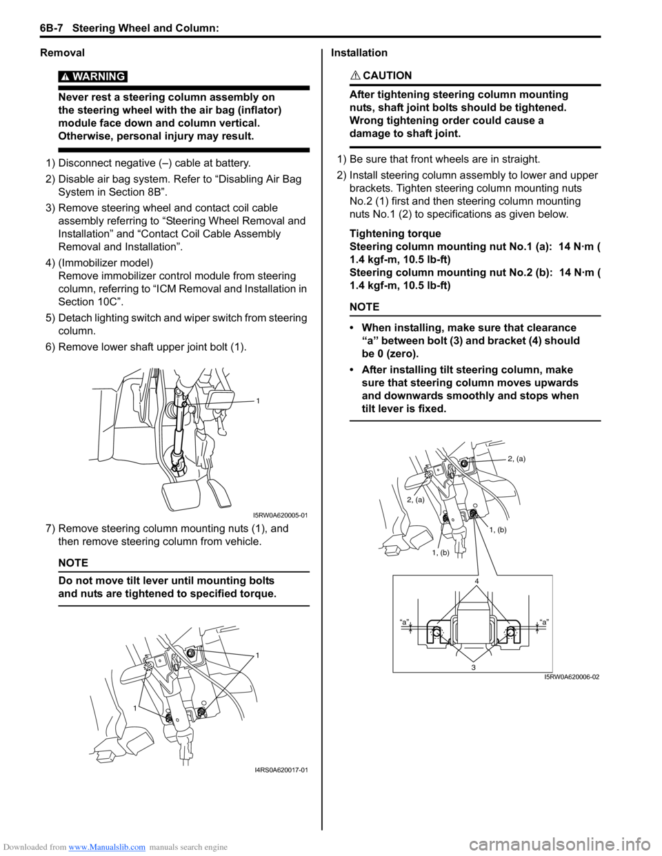
6) Remove lower shaft upper joint bolt (1).
7) Remove steering column mounting nuts (1), and
then remove steering column from vehicle.
NOTE
Do not move tilt lever until mounting bolts
and nuts are tightened to specified torque.
Installation
CAUTION!
After tightening steering column mounting
nuts, shaft joint bolts should be tightened.
Wrong tightening order could cause a
damage to shaft joint.
1) Be sure that front wheels are in straight.
2) Install steering column assembly to lower and upper
brackets. Tighten steering column mounting nuts
No.2 (1) first and then steering column mounting
nuts No.1 (2) to specifications as given below.
Tightening torque
Steering column mounting nut No.1 (a): 14 N·m (
1.4 kgf-m, 10.5 lb-ft)
Steering column mounting nut No.2 (b): 14 N·m (
1.4 kgf-m, 10.5 lb-ft)
NOTE
• When installing, make sure that clearance
“a” between bolt (3) and bracket (4) should
be 0 (zero).
• After installing tilt steering column, make
sure that steering column moves upwards
and downwards smoothly and stops when
tilt lever is fixed.
1
I5RW0A620005-01
1
1
I4RS0A620017-01
2, (a)
1, (b)
1, (b) 2, (a)
4
3“a” “a”
I5RW0A620006-02
Page 877 of 1556
Downloaded from www.Manualslib.com manuals search engine Steering Wheel and Column: 6B-8
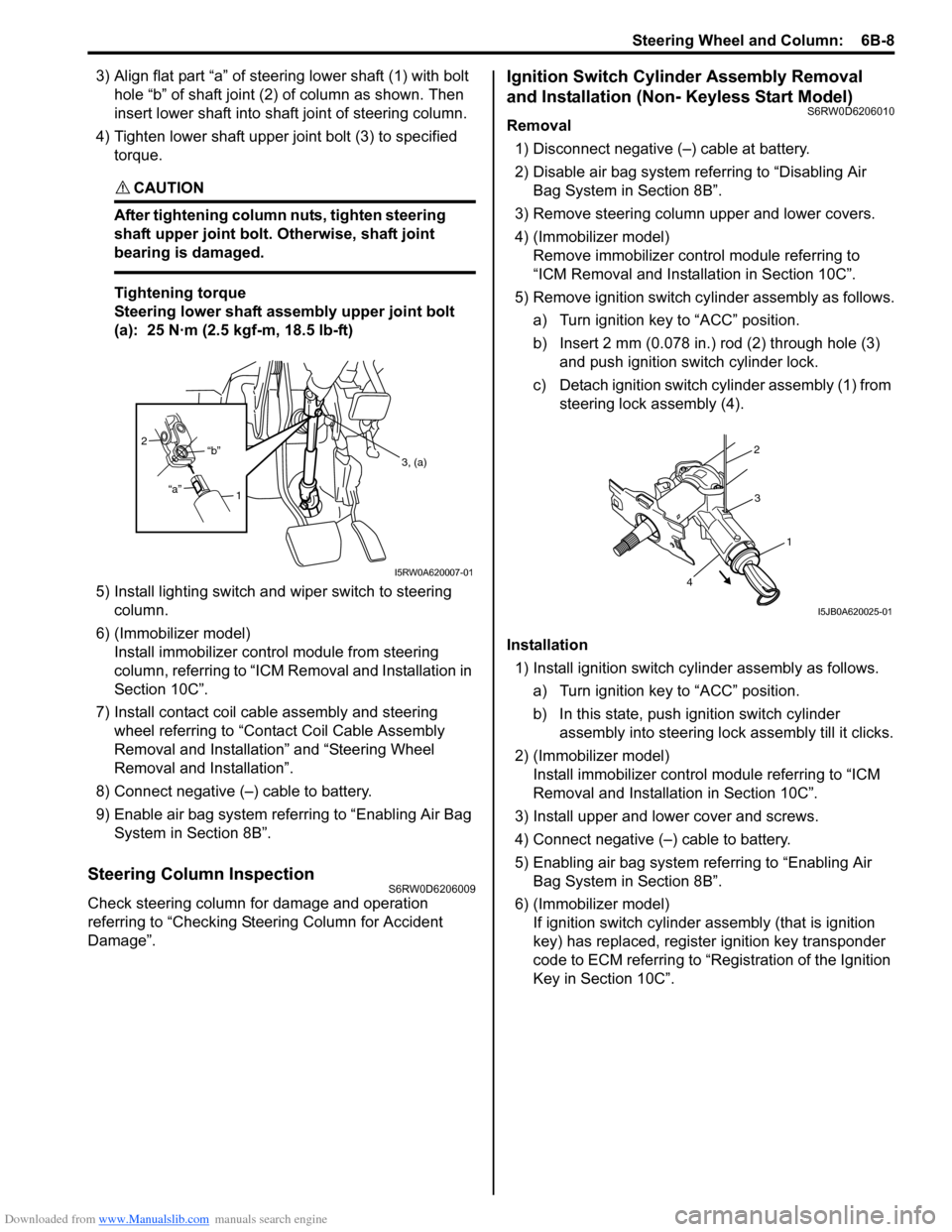
3) Align flat part “a” of steering lower shaft (1) with bolt
hole “b” of shaft joint (2) of column as shown. Then
insert lower shaft into shaft joint of steering column.
4) Tighten lower shaft upper joint bolt (3) to specified
torque.
CAUTION!
After tightening column nuts, tighten steering
shaft upper joint bolt. Otherwise, shaft joint
bearing is damaged.
Tightening torque
Steering lower shaft assembly upper joint bolt
(a): 25 N·m (2.5 kgf-m, 18.5 lb-ft)
5) Install lighting switch and wiper switch to steering
column.
6) (Immobilizer model)
Install immobilizer control module from steering
column, referring to “ICM Removal and Installation in
Section 10C”.
7) Install contact coil cable assembly and steering
wheel referring to “Contact Coil Cable Assembly
Removal and Installation” and “Steering Wheel
Removal and Installation”.
8) Connect negative (–) cable to battery.
9) Enable air bag system referring to “Enabling Air Bag
System in Section 8B”.
Steering Column InspectionS6RW0D6206009
Check steering column for damage and operation
referring to “Checking Steering Column for Accident
Damage”.
Ignition Switch Cylinder Assembly Removal
and Installation (Non- Keyless Start Model)
S6RW0D6206010
Removal
1) Disconnect negative (–) cable at battery.
2) Disable air bag system referring to “Disabling Air
Bag System in Section 8B”.
3) Remove steering column upper and lower covers.
4) (Immobilizer model)
Remove immobilizer control module referring to
“ICM Removal and Installation in Section 10C”.
5) Remove ignition switch cylinder assembly as follows.
a) Turn ignition key to “ACC” position.
b) Insert 2 mm (0.078 in.) rod (2) through hole (3)
and push ignition switch cylinder lock.
c) Detach ignition switch cylinder assembly (1) from
steering lock assembly (4).
Installation
1) Install ignition switch cylinder assembly as follows.
a) Turn ignition key to “ACC” position.
b) In this state, push ignition switch cylinder
assembly into steering lock assembly till it clicks.
2) (Immobilizer model)
Install immobilizer control module referring to “ICM
Removal and Installation in Section 10C”.
3) Install upper and lower cover and screws.
4) Connect negative (–) cable to battery.
5) Enabling air bag system referring to “Enabling Air
Bag System in Section 8B”.
6) (Immobilizer model)
If ignition switch cylinder assembly (that is ignition
key) has replaced, register ignition key transponder
code to ECM referring to “Registration of the Ignition
Key in Section 10C”.
1 2
“a”“b”
3, (a)
I5RW0A620007-01
2
3
1
4
I5JB0A620025-01
Page 914 of 1556
Downloaded from www.Manualslib.com manuals search engine 6C-34 Power Assisted Steering System:
Steering Wheel Play CheckS6RW0D6304021
• Check steering wheel for looseness or rattle by
moving it in its shaft direction and lateral direction.
If found defective, repair or replace.
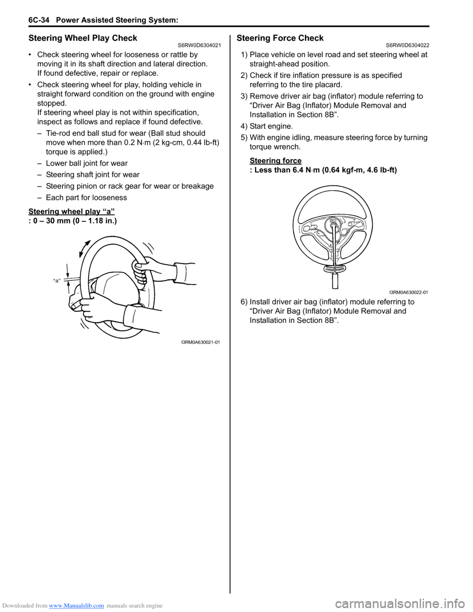
• Check steering wheel for play, holding vehicle in
straight forward condition on the ground with engine
stopped.
If steering wheel play is not within specification,
inspect as follows and replace if found defective.
– Tie-rod end ball stud for wear (Ball stud should
move when more than 0.2 N⋅m (2 kg-cm, 0.44 lb-ft)
torque is applied.)
– Lower ball joint for wear
– Steering shaft joint for wear
– Steering pinion or rack gear for wear or breakage
– Each part for looseness
Steering wheel play
“a”
: 0 – 30 mm (0 – 1.18 in.)
Steering Force CheckS6RW0D6304022
1) Place vehicle on level road and set steering wheel at
straight-ahead position.
2) Check if tire inflation pressure is as specified
referring to the tire placard.
3) Remove driver air bag (inflator) module referring to
“Driver Air Bag (Inflator) Module Removal and
Installation in Section 8B”.
4) Start engine.
5) With engine idling, measure steering force by turning
torque wrench.
Steering force
: Less than 6.4 N⋅m (0.64 kgf-m, 4.6 lb-ft)
6) Install driver air bag (inflator) module referring to
“Driver Air Bag (Inflator) Module Removal and
Installation in Section 8B”.
I3RM0A630021-01
I3RM0A630022-01
Page 917 of 1556
Downloaded from www.Manualslib.com manuals search engine Power Assisted Steering System: 6C-37
3) Inspect for proper toe referring to “Front Wheel
Alignment Inspection and Adjustment in Section 2B”.
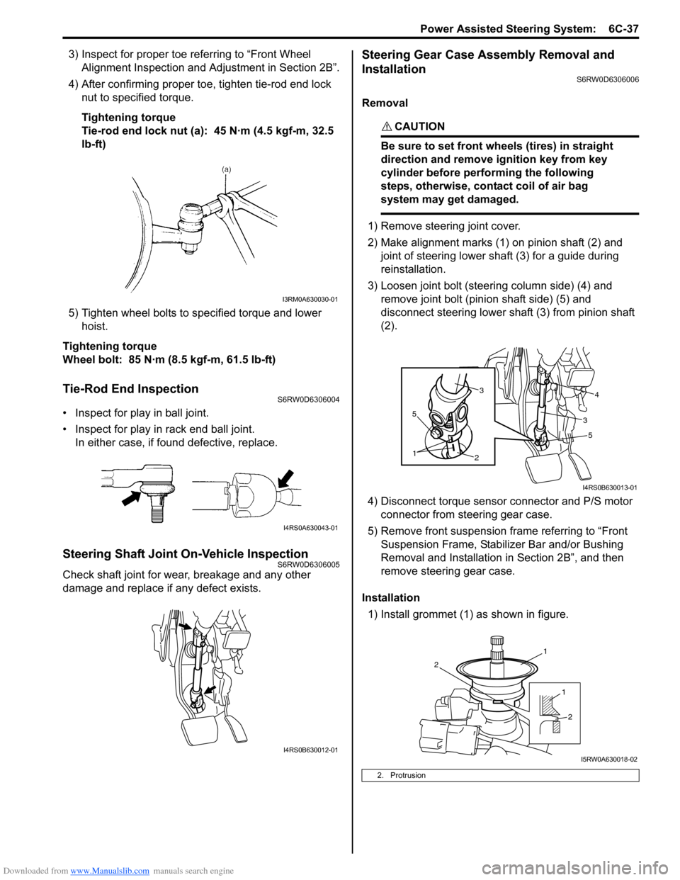
4) After confirming proper toe, tighten tie-rod end lock
nut to specified torque.
Tightening torque
Tie-rod end lock nut (a): 45 N·m (4.5 kgf-m, 32.5
lb-ft)
5) Tighten wheel bolts to specified torque and lower
hoist.
Tightening torque
Wheel bolt: 85 N·m (8.5 kgf-m, 61.5 lb-ft)
Tie-Rod End InspectionS6RW0D6306004
• Inspect for play in ball joint.
• Inspect for play in rack end ball joint.
In either case, if found defective, replace.
Steering Shaft Joint On-Vehicle InspectionS6RW0D6306005
Check shaft joint for wear, breakage and any other
damage and replace if any defect exists.
Steering Gear Case Assembly Removal and
Installation
S6RW0D6306006
Removal
CAUTION!
Be sure to set front wheels (tires) in straight
direction and remove ignition key from key
cylinder before performing the following
steps, otherwise, contact coil of air bag
system may get damaged.
1) Remove steering joint cover.
2) Make alignment marks (1) on pinion shaft (2) and
joint of steering lower shaft (3) for a guide during
reinstallation.
3) Loosen joint bolt (steering column side) (4) and
remove joint bolt (pinion shaft side) (5) and
disconnect steering lower shaft (3) from pinion shaft
(2).
4) Disconnect torque sensor connector and P/S motor
connector from steering gear case.
5) Remove front suspension frame referring to “Front
Suspension Frame, Stabilizer Bar and/or Bushing
Removal and Installation in Section 2B”, and then
remove steering gear case.
Installation
1) Install grommet (1) as shown in figure.
I3RM0A630030-01
I4RS0A630043-01
I4RS0B630012-01
2. Protrusion
5
2
1
5
34
3
I4RS0B630013-01
1
2
1
2
I5RW0A630018-02
Page 928 of 1556
Downloaded from www.Manualslib.com manuals search engine 7-1 Precautions:
HVAC
Precautions
Precautions
Precautions on HVACS6RW0D7000001
Air Bag Warning
Refer to “Air Bag Warning in Section 00”.
A/C System Caution
Refer to “A/C System Caution in Section 7B” or “A/C System Caution in Section 7B”.
Precautions on Servicing A/C System
Refer to “Precautions on Servicing A/C System in Section 7B” or “Precautions on Servicing A/C System in Section
7B”.
Precaution in Diagnosing Trouble (Automatic Type)
Refer to “Precautions in Diagnosing Trouble in Section 7B”.
Page 934 of 1556
Downloaded from www.Manualslib.com manuals search engine 7A-6 Heater and Ventilation:
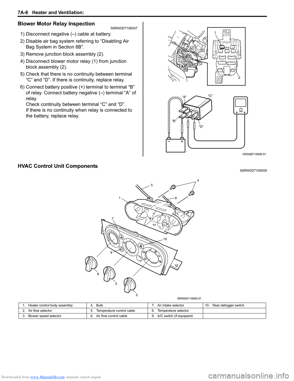
Blower Motor Relay InspectionS6RW0D7106007
1) Disconnect negative (–) cable at battery.
2) Disable air bag system referring to “Disabling Air
Bag System in Section 8B”.
3) Remove junction block assembly (2).
4) Disconnect blower motor relay (1) from junction
block assembly (2).
5) Check that there is no continuity between terminal
“C” and “D”. If there is continuity, replace relay.
6) Connect battery positive (+) terminal to terminal “B”
of relay. Connect battery negative (–) terminal “A” of
relay.
Check continuity between terminal “C” and “D”.
If there is no continuity when relay is connected to
the battery, replace relay.
HVAC Control Unit ComponentsS6RW0D7106008
“D” “B”“A”“C”
1
2
I4RS0B710008-01
1. Heater control body assembly 4. Bulb 7. Air intake selector 10. Rear defogger switch
2. Air flow selector 5. Temperature control cable 8. Temperature selector
3. Blower speed selector 6. Air flow control cable 9. A/C switch (if equipped)
7
10
9
2
3 8
45
61
I5RW0A710005-01