Sensors SUZUKI SX4 2006 1.G Service Owner's Manual
[x] Cancel search | Manufacturer: SUZUKI, Model Year: 2006, Model line: SX4, Model: SUZUKI SX4 2006 1.GPages: 1556, PDF Size: 37.31 MB
Page 396 of 1556
Downloaded from www.Manualslib.com manuals search engine 1H-1 Ignition System:
Engine
Ignition System
General Description
Ignition System ConstructionS6RW0D1801001
The ignition system is an electronic (distributorless) ignition system. It consists of the parts as described below.
•ECM
It detects the engine and vehicle conditions through the signals from the sensors, determines the most suitable
ignition timing and time for electricity to flow to the primary coil and sends a signal to the ignitor (power unit) in the
ignition coil assembly.
•Ignition coil assembly (including an ignitor)
The ignition coil assembly has a built-in ignitor which turns ON and OFF the current flow to the primary coil
according to the signal from ECM. When the current flow to the primary coil is turned OFF, a high voltage is induced
in the secondary coil.
•High-tension cords and spark plugs
•CMP sensor (Camshaft position sensor) and CKP sensor (Crankshaft position sensor)
Using signals from these sensors, ECM identifies the specific cylinder whose piston is in the compression stroke,
detects the crank angle and adjusts initial ignition timing automatically.
•TP sensor, ECT sensor, MAP sensor, MAF sensor, IAT sensor, knock sensor and other sensors / switches
Although this ignition system does not have a distributor, it has two ignition coil assemblies (one is for No.1 and No.4
spark plugs and the other is for No.2 and No.3 spark plugs). When an ignition signal is sent from ECM to the ignitor in
the ignition coil assembly for No.1 and No.4 spark plugs, a high voltage is induced in the secondary coil and that
passes through the high-tension cords and causes No.1 and No.4 spark plugs to spark simultaneously. Likewise,
when an ignition signal is sent to the ignitor in the other ignition coil assembly, No.2 and No.3 spark plugs spark
simultaneously.
Page 399 of 1556
Downloaded from www.Manualslib.com manuals search engine Ignition System: 1H-4
Diagnostic Information and Procedures
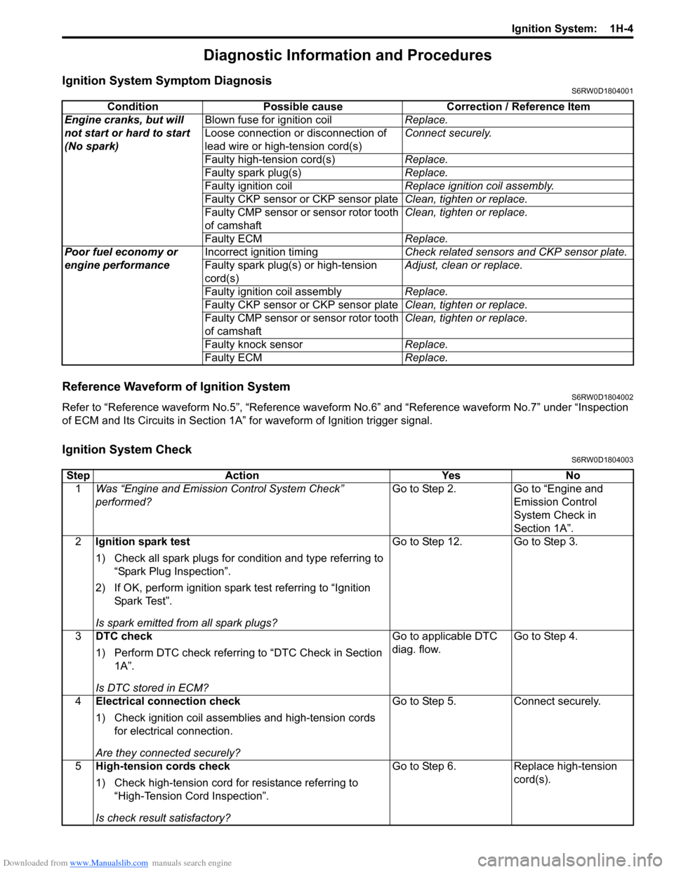
Ignition System Symptom DiagnosisS6RW0D1804001
Reference Waveform of Ignition SystemS6RW0D1804002
Refer to “Reference waveform No.5”, “Reference waveform No.6” and “Reference waveform No.7” under “Inspection
of ECM and Its Circuits in Section 1A” for waveform of Ignition trigger signal.
Ignition System CheckS6RW0D1804003
Condition Possible cause Correction / Reference Item
Engine cranks, but will
not start or hard to start
(No spark)Blown fuse for ignition coilReplace.
Loose connection or disconnection of
lead wire or high-tension cord(s)Connect securely.
Faulty high-tension cord(s)Replace.
Faulty spark plug(s)Replace.
Faulty ignition coilReplace ignition coil assembly.
Faulty CKP sensor or CKP sensor plateClean, tighten or replace.
Faulty CMP sensor or sensor rotor tooth
of camshaftClean, tighten or replace.
Faulty ECMReplace.
Poor fuel economy or
engine performanceIncorrect ignition timingCheck related sensors and CKP sensor plate.
Faulty spark plug(s) or high-tension
cord(s)Adjust, clean or replace.
Faulty ignition coil assemblyReplace.
Faulty CKP sensor or CKP sensor plateClean, tighten or replace.
Faulty CMP sensor or sensor rotor tooth
of camshaftClean, tighten or replace.
Faulty knock sensorReplace.
Faulty ECMReplace.
Step Action Yes No
1Was “Engine and Emission Control System Check”
performed?Go to Step 2. Go to “Engine and
Emission Control
System Check in
Section 1A”.
2Ignition spark test
1) Check all spark plugs for condition and type referring to
“Spark Plug Inspection”.
2) If OK, perform ignition spark test referring to “Ignition
Spar k Tes t”.
Is spark emitted from all spark plugs?Go to Step 12. Go to Step 3.
3DTC check
1) Perform DTC check referring to “DTC Check in Section
1A”.
Is DTC stored in ECM?Go to applicable DTC
diag. flow.Go to Step 4.
4Electrical connection check
1) Check ignition coil assemblies and high-tension cords
for electrical connection.
Are they connected securely?Go to Step 5. Connect securely.
5High-tension cords check
1) Check high-tension cord for resistance referring to
“High-Tension Cord Inspection”.
Is check result satisfactory?Go to Step 6. Replace high-tension
cord(s).
Page 606 of 1556
Downloaded from www.Manualslib.com manuals search engine 4E-1 ABS:
Brakes
ABS
Precautions
Precautions in Diagnosing TroublesS6RW0D4500001
To ensure that the trouble diagnosis is done accurately
and smoothly, observe the following and follow “ABS
Check”.
• Diagnostic information stored in ABS control module
memory can be cleared as well as checked by using
SUZUKI scan tool. Before using scan tool, read its
Operator's (Instruction) Manual carefully to have good
understanding as to what functions are available and
how to use it.
• If the vehicle was operated in any of the following
ways, ABS warning light may light momentarily but
this does not indicate anything abnormal in ABS.
– The vehicle was driven with parking brake pulled.
– The vehicle was driven with brake dragging.
– The vehicle was stuck in mud, sand, etc.
– Wheel spin occurred while driving.
– Wheel(s) was rotated while the vehicle was jacked
up.
• Be sure to read “Precautions for Electrical Circuit
Service in Section 00” and “Precaution for CAN
Communication System in Section 00” before
inspection and observe what is written there.
• Be sure to use the trouble diagnosis procedure as
described in “ABS Check”. Failure to follow it may
result in incorrect diagnosis. (Some other diagnosis
trouble code may be stored by mistake in the memory
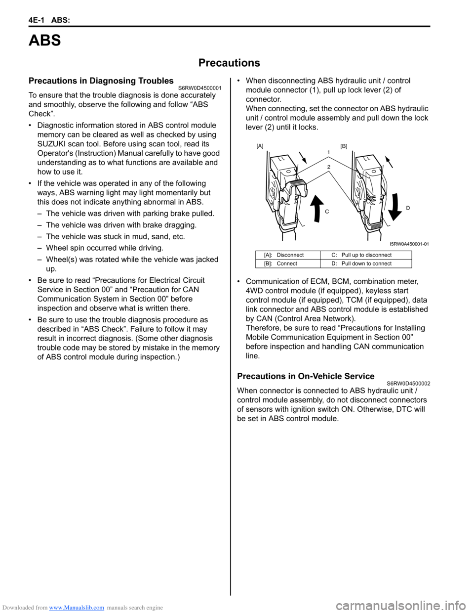
of ABS control module during inspection.)• When disconnecting ABS hydraulic unit / control
module connector (1), pull up lock lever (2) of
connector.
When connecting, set the connector on ABS hydraulic
unit / control module assembly and pull down the lock
lever (2) until it locks.
• Communication of ECM, BCM, combination meter,
4WD control module (if equipped), keyless start
control module (if equipped), TCM (if equipped), data
link connector and ABS control module is established
by CAN (Control Area Network).
Therefore, be sure to read “Precautions for Installing
Mobile Communication Equipment in Section 00”
before inspection and handling CAN communication
line.
Precautions in On-Vehicle ServiceS6RW0D4500002
When connector is connected to ABS hydraulic unit /
control module assembly, do not disconnect connectors
of sensors with ignition switch ON. Otherwise, DTC will
be set in ABS control module.
[A]: Disconnect C: Pull up to disconnect
[B]: Connect D: Pull down to connect
2 1
CD
[A]
[B]
I5RW0A450001-01
Page 613 of 1556
Downloaded from www.Manualslib.com manuals search engine ABS: 4E-8
Component Location
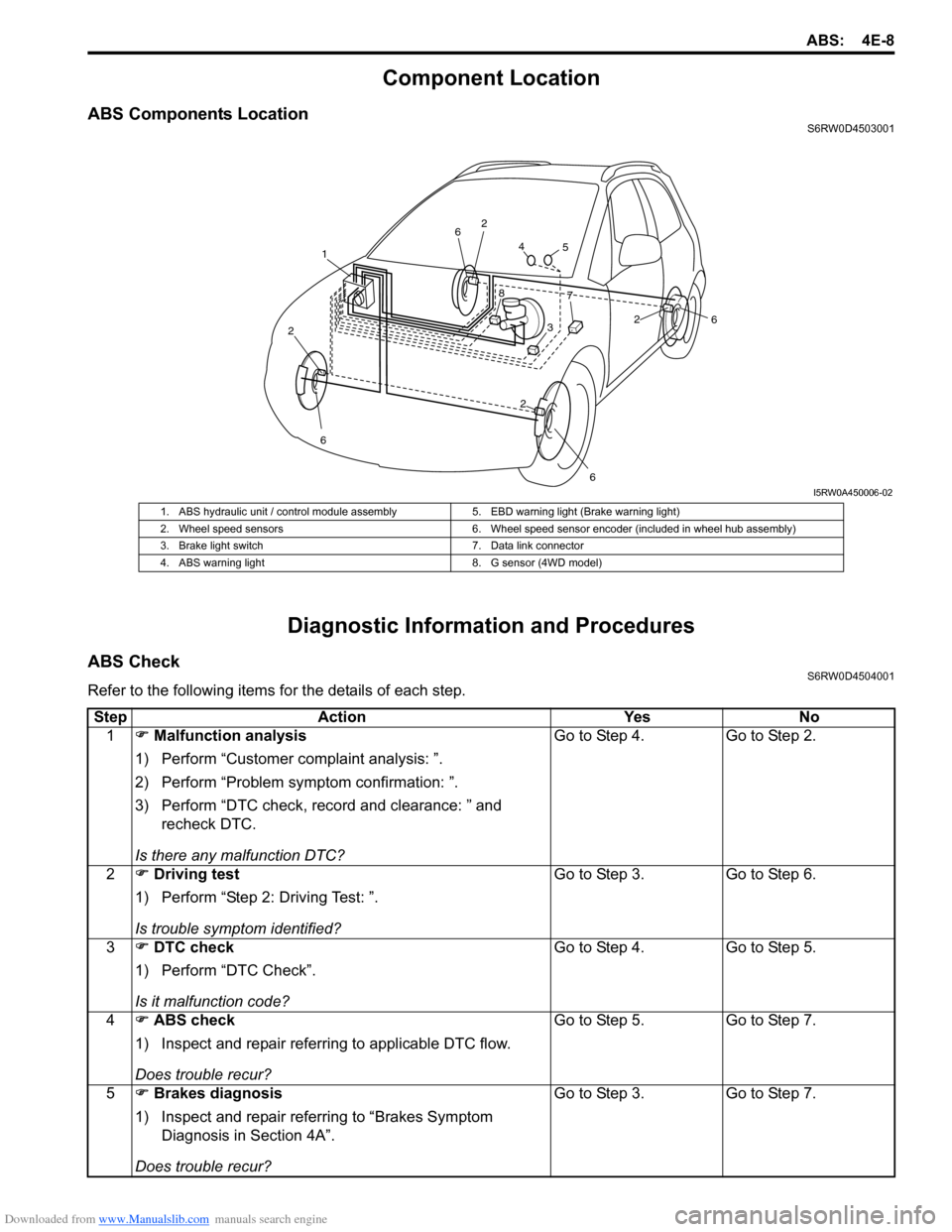
ABS Components LocationS6RW0D4503001
Diagnostic Information and Procedures
ABS CheckS6RW0D4504001
Refer to the following items for the details of each step.
1
2
6
2
6
26
264
5
7
3
8
I5RW0A450006-02
1. ABS hydraulic unit / control module assembly 5. EBD warning light (Brake warning light)
2. Wheel speed sensors 6. Wheel speed sensor encoder (included in wheel hub assembly)
3. Brake light switch 7. Data link connector
4. ABS warning light 8. G sensor (4WD model)
Step Action Yes No
1�) Malfunction analysis
1) Perform “Customer complaint analysis: ”.
2) Perform “Problem symptom confirmation: ”.
3) Perform “DTC check, record and clearance: ” and
recheck DTC.
Is there any malfunction DTC?Go to Step 4. Go to Step 2.
2�) Driving test
1) Perform “Step 2: Driving Test: ”.
Is trouble symptom identified?Go to Step 3. Go to Step 6.
3�) DTC check
1) Perform “DTC Check”.
Is it malfunction code?Go to Step 4. Go to Step 5.
4�) ABS check
1) Inspect and repair referring to applicable DTC flow.
Does trouble recur?Go to Step 5. Go to Step 7.
5�) Brakes diagnosis
1) Inspect and repair referring to “Brakes Symptom
Diagnosis in Section 4A”.
Does trouble recur?Go to Step 3. Go to Step 7.
Page 630 of 1556
Downloaded from www.Manualslib.com manuals search engine 4E-25 ABS:
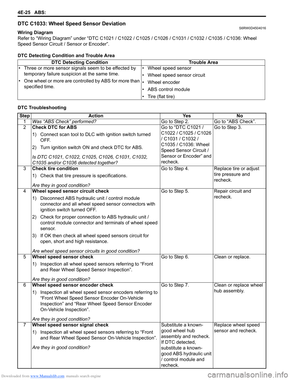
DTC C1033: Wheel Speed Sensor DeviationS6RW0D4504016
Wiring Diagram
Refer to “Wiring Diagram” under “DTC C1021 / C1022 / C1025 / C1026 / C1031 / C1032 / C1035 / C1036: Wheel
Speed Sensor Circuit / Sensor or Encoder”.
DTC Detecting Condition and Trouble Area
DTC Troubleshooting DTC Detecting Condition Trouble Area
• Three or more sensor signals seem to be effected by
temporary failure suspicion at the same time.
• One wheel or more are controlled by ABS for more than
specified time.• Wheel speed sensor
• Wheel speed sensor circuit
• Wheel encoder
• ABS control module
• Tire (flat tire)
Step Action Yes No
1Was “ABS Check” performed?Go to Step 2. Go to “ABS Check”.
2Check DTC for ABS
1) Connect scan tool to DLC with ignition switch turned
OFF.
2) Turn ignition switch ON and check DTC for ABS.
Is DTC C1021, C1022, C1025, C1026, C1031, C1032,
C1035 and/or C1036 detected together?Go to “DTC C1021 /
C1022 / C1025 / C1026
/ C1031 / C1032 /
C1035 / C1036: Wheel
Speed Sensor Circuit /
Sensor or Encoder” and
recheck.Go to Step 3.
3Check tire condition
1) Check that tire pressure is specifications.
Are they in good condition?Go to Step 4. Replace tire or adjust
tire pressure and
recheck.
4Wheel speed sensor circuit check
1) Disconnect ABS hydraulic unit / control module
connector and all wheel speed sensor connectors with
ignition switch turned OFF.
2) Check for proper connection to ABS hydraulic unit /
control module connector and terminals of wheel speed
sensor.
3) If OK then check all wheel speed sensors circuit for
open, short and high resistance.
Are wheel speed sensor circuits in good condition?Go to Step 5. Repair circuit and
recheck.
5Wheel speed sensor check
1) Inspection all wheel speed sensors referring to “Front
and Rear Wheel Speed Sensor Inspection”.
Are they in good condition?Go to Step 6. Clean or replace.
6Wheel speed sensor encoder check
1) Inspection all wheel speed sensor encoders referring to
“Front Wheel Speed Sensor Encoder On-Vehicle
Inspection” and “Rear Wheel Speed Sensor Encoder
On-Vehicle Inspection”.
Are they in good condition?Go to Step 7. Clean or replace wheel
hub assembly.
7Wheel speed sensor signal check
1) Inspection all wheel speed sensors referring to “Front
and Rear Wheel Speed Sensor On-Vehicle Inspection”.
Are they in good condition?Substitute a known-
good wheel hub
assembly and recheck.
If DTC detected,
substitute a known-
good ABS hydraulic unit
/ control module and
recheck.Replace wheel speed
sensor and recheck.
Page 885 of 1556
Downloaded from www.Manualslib.com manuals search engine Power Assisted Steering System: 6C-5
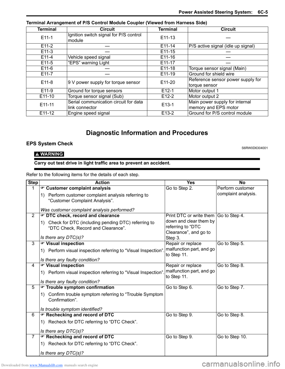
Terminal Arrangement of P/S Control Module Coupler (Viewed from Harness Side)
Diagnostic Information and Procedures
EPS System CheckS6RW0D6304001
WARNING!
Carry out test drive in light traffic area to prevent an accident.
Refer to the following items for the details of each step.Terminal Circuit Terminal Circuit
E11-1Ignition switch signal for P/S control
moduleE11-13 —
E11-2 — E11-14 P/S active signal (idle up signal)
E11-3 — E11-15 —
E11-4 Vehicle speed signal E11-16 —
E11-5 “EPS” warning Light E11-17 —
E11-6 — E11-18 Torque sensor signal (Main)
E11-7 — E11-19 Ground for shield wire
E11-8 9 V power supply for torque sensor E11-20Reference sensor power supply for
torque sensor
E11-9 Ground for torque sensors E12-1 Motor output 1
E11-10 Torque sensor signal (Sub) E12-2 Motor output 2
E11-11Serial communication circuit for data
link connectorE13-1Main power supply for internal
memory and EPS motor
E11-12 Engine speed signal E13-2 Ground for P/S control module
Step Action Yes No
1�) Customer complaint analysis
1) Perform customer complaint analysis referring to
“Customer Complaint Analysis”.
Was customer complaint analysis performed?Go to Step 2. Perform customer
complaint analysis.
2�) DTC check, record and clearance
1) Check for DTC (including pending DTC) referring to
“DTC Check, Record and Clearance”.
Is there any DTC(s)?Print DTC or write them
down and clear them by
referring to “DTC
Clearance”, and go to
St ep 3 .Go to Step 4.
3�) Visual inspection
1) Perform visual inspection referring to “Visual Inspection”.
Is there any faulty condition?Repair or replace
malfunction part, and go
to Step 11.Go to Step 5.
4�) Visual inspection
1) Perform visual inspection referring to “Visual Inspection”.
Is there any faulty condition?Repair or replace
malfunction part, and go
to Step 11.Go to Step 8.
5�) Trouble symptom confirmation
1) Confirm trouble symptom referring to “Trouble Symptom
Confirmation”.
Is trouble symptom identified?Go to Step 6. Go to Step 7.
6�) Rechecking and record of DTC
1) Recheck for DTC referring to “DTC Check”.
Is there any DTC(s)?Go to Step 9. Go to Step 8.
7�) Rechecking and record of DTC
1) Recheck for DTC referring to “DTC Check”.
Is there any DTC(s)?Go to Step 9. Go to Step 10.
Page 911 of 1556
Downloaded from www.Manualslib.com manuals search engine Power Assisted Steering System: 6C-31
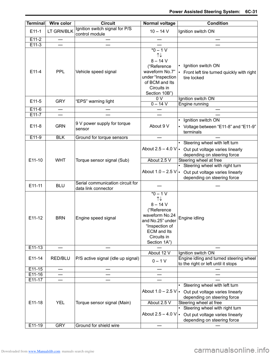
Terminal Wire color Circuit Normal voltage Condition
E11-1 LT GRN/BLKIgnition switch signal for P/S
control module10 – 14 V Ignition switch ON
E11-2 — — — —
E11-3 — — — —
E11-4 PPL Vehicle speed signal*0 – 1 V
↑↓
8 – 14 V
(“Reference
waveform No.7”
under “Inspection
of BCM and Its
Circuits in
Section 10B”)• Ignition switch ON
• Front left tire turned quickly with right
tire locked
E11-5 GRY “EPS” warning light0 V Ignition switch ON
0 – 14 V Engine running
E11-6 — — — —
E11-7 — — — —
E11-8 GRN9 V power supply for torque
sensorAbout 9 V• Ignition switch ON
• Voltage between “E11-8” and “E11-9”
terminals
E11-9 BLK Ground for torque sensors — —
E11-10 WHT Torque sensor signal (Sub)About 2.5 – 4.0 V• Steering wheel with left turn
• Out put voltage varies linearly
depending on steering force
About 2.5 V Steering wheel at free
About 1.0 – 2.5 V• Steering wheel with right turn
• Out put voltage varies linearly
depending on steering force
E11-11 BLUSerial communication circuit for
data link connector——
E11-12 BRN Engine speed signal*0 – 1 V
↑↓
8 – 14 V
(“Reference
waveform No.24
and No.25” under
“Inspection of
ECM and Its
Circuits in
Section 1A”)Engine idling
E11-13 — — — —
E11-14 RED/BLU P/S active signal (idle up signal)About 12 V Ignition switch ON
0 – 1 VEngine idling and turned steering wheel
to the right or left until it stops
E11-15 — — — —
E11-16 — — — —
E11-17 — — — —
E11-18 YEL Torque sensor signal (Main)About 1.0 – 2.5 V• Steering wheel with left turn
• Out put voltage varies linearly
depending on steering force
About 2.5 V Steering wheel at free
About 2.5 – 4.0 V• Steering wheel with right turn
• Out put voltage varies linearly
depending on steering force
E11-19 GRY Ground for shield wire — —
Page 997 of 1556
Downloaded from www.Manualslib.com manuals search engine Air Conditioning System: Automatic Type 7B-57
SUN LOAD (W/m2): This parameter indicates the
amount of sunlight detected by sunload sensor.
MODE CONT SWITCH (Air flow selector position,
AUTO, FACE, B/L, FOOT, D/F, DEF): This
parameter indicates the selected position of air flow
selector.
FAN CONT SWITCH (Blower speed selector, AUTO,
OFF, 1st – 8th): This parameter indicates the
selected position of blower speed selector.
FAN DESIRE VOLT (Fan desired voltage, V): This
parameter indicates the consumption voltage of
blower motor.
AIR MIX POS SENSOR (Temperature control
actuator position sensor, V): This parameter
indicates the input signal from position sensor in
temperature control actuator.
MODE POS SENSOR (Air flow control actuator
position sensor, V): This parameter indicates the
input signal from position sensor in air flow control
actuator.
A/C CONT SIG (A/C control signal, ON, OFF): This
parameter indicates the state of A/C switch.BLOWER LOAD SIG (Blower fan load signal, ON,
OFF): ON: Position of blower speed selector is 1st
position or more.
OFF: Position of blower speed selector is OFF
position.
AIR INTAKE MODE (Air intake selector position,
AUTO, FRE, REC): This parameter indicates the
selected position of air intake selector.
REFRIGERANT PRESSURE (A/C refrigerant absolute
pressure, kPa): This parameter indicates the A/C
refrigerant absolute pressure calculated by ECM
A/C COMP CLUCH (A/C compressor magnet clutch,
ON, OFF): This parameter indicates the state of the
A/C compressor magnet clutch.
VEHICLE SPEED (km/h, mph): This parameter
indicates the vehicle speed calculated by ECM.
ENGINE TYPE (Engine type signal, J20, M16 or
M15): This parameter indicates the engine type
signal transmitted by ECM.
METER SPEC (Combination meter spec signal, EU,
UK, US, Canada, DOM): This parameter indicates
the combination meter spec signal transmitted by
combination meter.
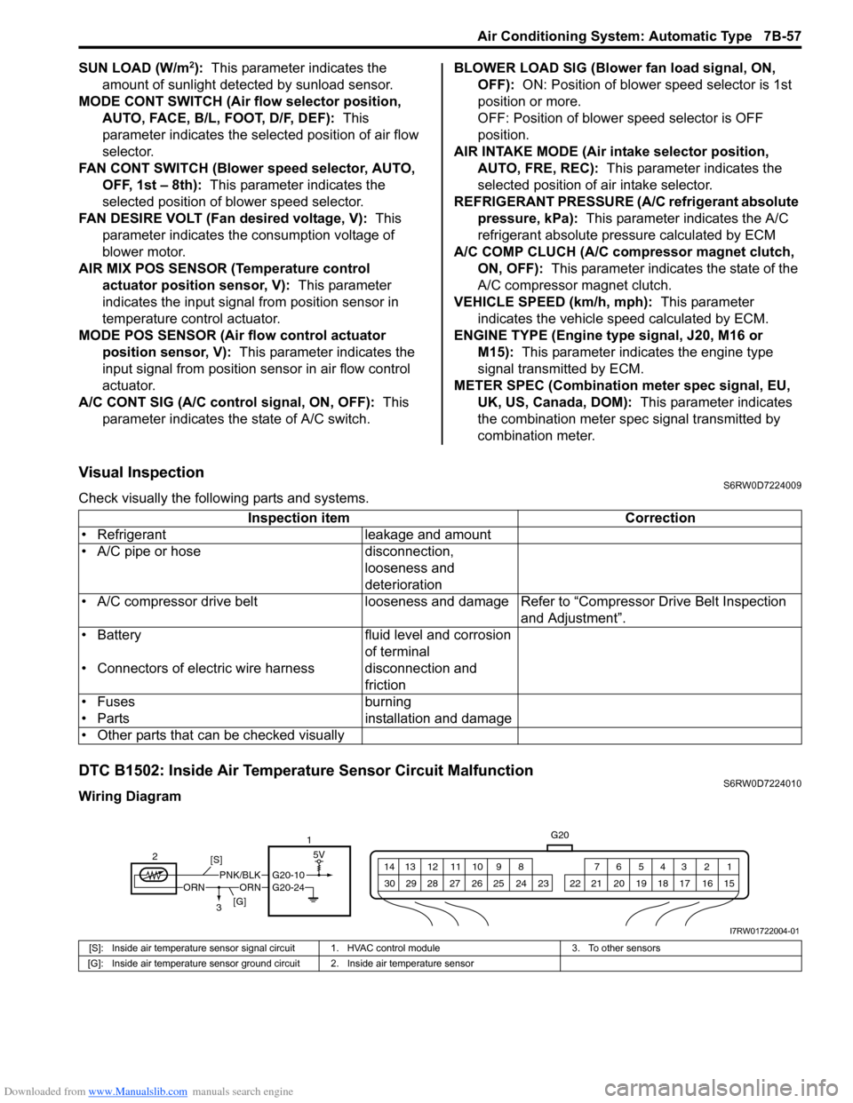
Visual InspectionS6RW0D7224009
Check visually the following parts and systems.
DTC B1502: Inside Air Temperature Sensor Circuit MalfunctionS6RW0D7224010
Wiring DiagramInspection item Correction
• Refrigerant leakage and amount
• A/C pipe or hose disconnection,
looseness and
deterioration
• A/C compressor drive belt looseness and damageRefer to “Compressor Drive Belt Inspection
and Adjustment”.
• Battery fluid level and corrosion
of terminal
• Connectors of electric wire harness disconnection and
friction
• Fuses burning
• Parts installation and damage
• Other parts that can be checked visually
5V
G20
1 2 3 4 5 6 7 8 9 10 11 12 13 14
15 16 17 18 19 20 21 24 23 22 25 26 27 28 29 30
ORNORNPNK/BLKG20-10
21
3 [S]
[G]
G20-24
I7RW01722004-01
[S]: Inside air temperature sensor signal circuit 1. HVAC control module 3. To other sensors
[G]: Inside air temperature sensor ground circuit 2. Inside air temperature sensor
Page 999 of 1556

Downloaded from www.Manualslib.com manuals search engine Air Conditioning System: Automatic Type 7B-59
DTC B1503: Evaporator Temperature Sensor Circuit MalfunctionS6RW0D7224011
Wiring Diagram
DTC Detecting Condition and Trouble Area
DTC Troubleshooting
NOTE
When DTC B1502, B1504, B1511 and B1512 are indicated together, it is possible that sensor ground
circuit is open.
5V
G20
1 2 3 4 5 6 7 8 9 10 11 12 13 14
15 16 17 18 19 20 21 24 23 22 25 26 27 28 29 30
ORNORNWHT/BLKG20-9G20-24
[S]
[G] 2
31
I7RW01722005-01
[S]: Evaporator temperature sensor signal circuit 1. HVAC control module 3. To other sensors
[G]: Evaporator temperature sensor ground circuit 2. Evaporator temperature sensor
DTC Detecting Condition Trouble Area
Evaporator temperature sensor signal voltage is higher than or lower than
specified value for specified time continuously.• Evaporator temperature sensor
circuit
• Evaporator temperature sensor
• HVAC control module
Step Action Yes No
1Was “Air Conditioning System Check” performed?Go to Step 2. Go to “Air Conditioning
System Check”.
2Wire harness check
1) Turn ignition switch to OFF position.
2) Disconnect connectors from evaporator temperature
sensor and HVAC control module.
3) Check for proper connection to each signal circuit
terminal and ground circuit terminal of evaporator
temperature sensor and HVAC control module
connectors.
4) If OK, check that evaporator temperature sensor circuit
is as follows.
• Wiring harness resistance of each evaporator
temperature sensor signal circuit and ground circuit is
less than 3 Ω
• Insulation resistance between evaporator temperature
sensor signal circuit and vehicle body ground is
Infinity
• Circuit voltage of each evaporator temperature sensor
signal circuit and ground circuit is 0 - 1 V with ignition
switch turned ON
Are they good condition?Go to Step 3. Evaporator temperature
sensor signal circuit
and/or ground circuit are
open, short or high
resistance.
Page 1000 of 1556
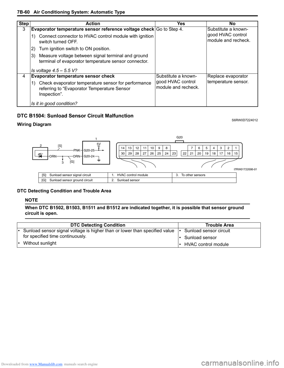
Downloaded from www.Manualslib.com manuals search engine 7B-60 Air Conditioning System: Automatic Type
DTC B1504: Sunload Sensor Circuit MalfunctionS6RW0D7224012
Wiring Diagram
DTC Detecting Condition and Trouble Area
NOTE
When DTC B1502, B1503, B1511 and B1512 are indicated together, it is possible that sensor ground
circuit is open.
3Evaporator temperature sensor reference voltage check
1) Connect connector to HVAC control module with ignition
switch turned OFF.
2) Turn ignition switch to ON position.
3) Measure voltage between signal terminal and ground
terminal of evaporator temperature sensor connector.
Is voltage 4.5 – 5.5 V?Go to Step 4. Substitute a known-
good HVAC control
module and recheck.
4Evaporator temperature sensor check
1) Check evaporator temperature sensor for performance
referring to “Evaporator Temperature Sensor
Inspection”.
Is it in good condition?Substitute a known-
good HVAC control
module and recheck.Replace evaporator
temperature sensor. Step Action Yes No
G20
1 2 3 4 5 6 7 8 9 10 11 12 13 14
15 16 17 18 19 20 21 24 23 22 25 26 27 28 29 30
PNK
ORNORN
G20-25
G20-24
2
[S]
[G]15V
3
I7RW01722006-01
[S]: Sunload sensor signal circuit 1. HVAC control module 3. To other sensors
[G]: Sunload sensor ground circuit 2. Sunload sensor
DTC Detecting Condition Trouble Area
• Sunload sensor signal voltage is higher than or lower than specified value
for specified time continuously.
• Without sunlight• Sunload sensor circuit
• Sunload sensor
• HVAC control module