main fuse box SUZUKI SX4 2006 1.G Service Owner's Manual
[x] Cancel search | Manufacturer: SUZUKI, Model Year: 2006, Model line: SX4, Model: SUZUKI SX4 2006 1.GPages: 1556, PDF Size: 37.31 MB
Page 243 of 1556
Downloaded from www.Manualslib.com manuals search engine Engine General Information and Diagnosis: 1A-193
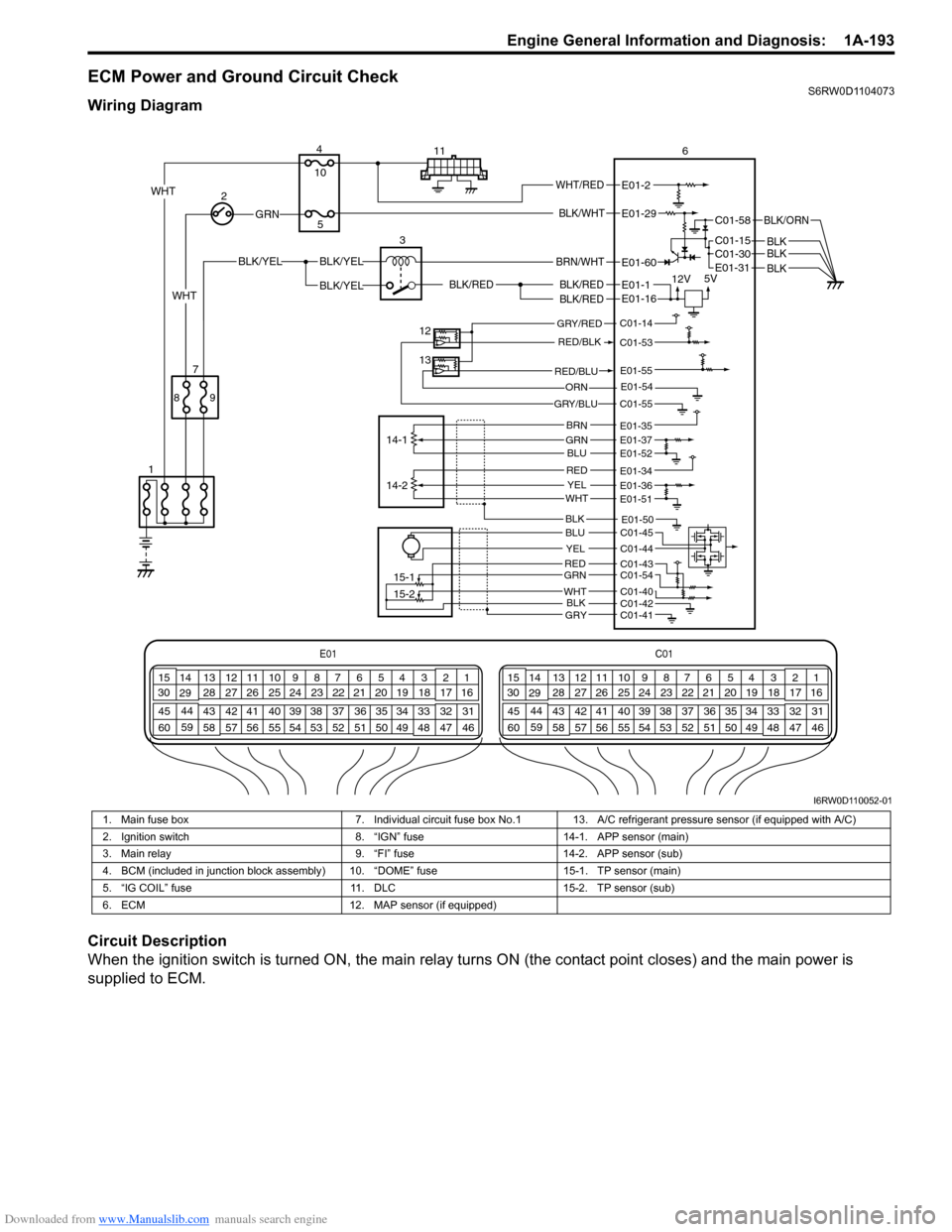
ECM Power and Ground Circuit CheckS6RW0D1104073
Wiring Diagram
Circuit Description
When the ignition switch is turned ON, the main relay turns ON (the contact point closes) and the main power is
supplied to ECM.
E01C01
3 4
18 19 5 6 7 10 11
17 20
47 46 49 50 51 21 22
5216 259
24 14
29
55 57 54 53 59
60 582
26 27 28 15
30
56 4832 31 34 35 36 37 40 42 39 38 44
45 43 41 331 12 13
238 3 4
18 19 5 6 7 10 11
17 20
47 46 49 50 51 21 22
5216 259
24 14
29
55 57 54 53 59
60 582
26 27 28 15
30
56 4832 31 34 35 36 37 40 42 39 38 44
45 43 41 331 12 13
238
BLK/WHT
BLK/RED
BLK/RED
BLK/RED
BLK/YELBLK/YEL
BLK/YEL
GRN
BRN/WHT
12V5V
2
13
12
13
14-1
15-1
15-2 14-2 4
56
E01-29
E01-1
E01-60
E01-16
9 87
1011
WHTWHT/REDE01-2
C01-58
C01-15 C01-30
BLK/ORN
BLKBLKBLK
WHT
GRY/RED
RED/BLK
GRY/BLU
C01-14
C01-53
C01-55
E01-54ORN
RED/BLUE01-55
BRNGRNBLU
REDYELWHT
E01-35E01-37E01-52
E01-51
E01-34E01-36
E01-50
REDGRN
WHTBLK
BLU
YEL
C01-43C01-54
C01-40C01-42
C01-45
C01-44
C01-41
E01-31
GRY
BLK
I6RW0D110052-01
1. Main fuse box 7. Individual circuit fuse box No.1 13. A/C refrigerant pressure sensor (if equipped with A/C)
2. Ignition switch 8. “IGN” fuse 14-1. APP sensor (main)
3. Main relay 9. “FI” fuse 14-2. APP sensor (sub)
4. BCM (included in junction block assembly) 10. “DOME” fuse 15-1. TP sensor (main)
5. “IG COIL” fuse 11. DLC 15-2. TP sensor (sub)
6. ECM 12. MAP sensor (if equipped)
Page 244 of 1556
Downloaded from www.Manualslib.com manuals search engine 1A-194 Engine General Information and Diagnosis:
Troubleshooting
NOTE
• Before performed trouble shooting, be sure to read the “Precautions of ECM Circuit Inspection”.
• When measuring circuit voltage, resistance and/or pulse signal at ECM connector, connect the
special tool to ECM and/or the ECM connectors referring to “Inspection of ECM and Its Circuits”.
Step Action Yes No
1Circuit fuse check
1) Disconnect connectors from ECM with ignition switch
turned OFF.
2) Check for proper connection to ECM connector at “E01-
2”, “E01-29”, “E01-60”, “E01-1”, “E01-16”, “E01-31”,
“C01-58”, “C01-15” and “C01-30” terminals.
3) If OK, check “DOME” fuse and “IG COIL” fuse for
blowing.
Are “DOME” fuse and “IG COIL” fuse in good condition?Go to Step 2. Replace fuse (s) and
check for short in
circuits connected to
fuse(s).
2Power supply circuit check
1) Measure voltage between “E01-2” terminal of ECM
connector and body ground.
Is voltage 10 – 14 V?Go to Step 3. “WHT/RED” or “WHT”
wire is open circuit.
3Ignition signal check
1) Turn ignition switch to ON position.
2) Measure voltage between “E01-29” terminal of ECM
connector and body ground.
Is voltage 10 – 14 V?Go to Step 4. “BLK/WHT” or “GRN”
wire is open circuit.
4Main relay circuit check
1) Turn ignition switch to OFF position.
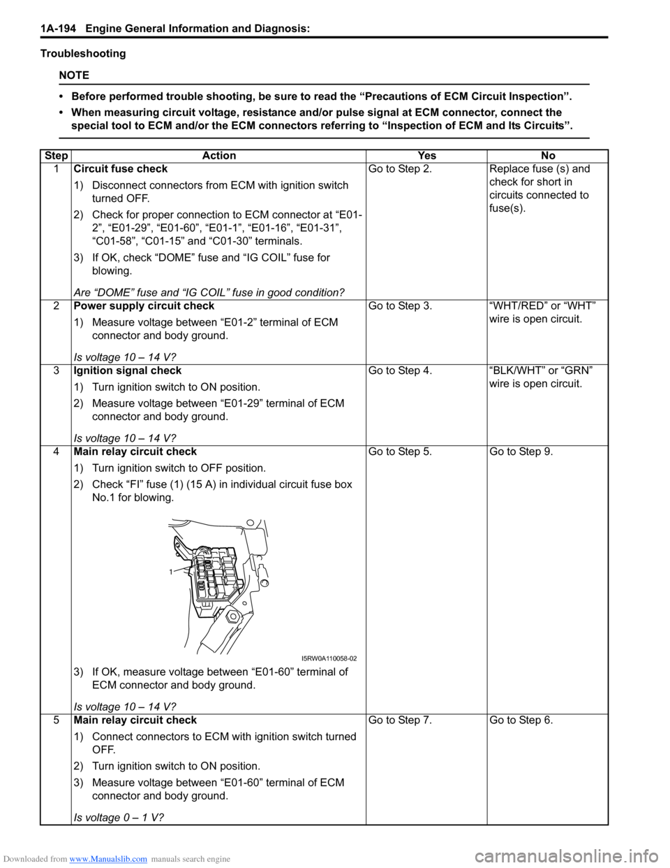
2) Check “FI” fuse (1) (15 A) in individual circuit fuse box
No.1 for blowing.
3) If OK, measure voltage between “E01-60” terminal of
ECM connector and body ground.
Is voltage 10 – 14 V?Go to Step 5. Go to Step 9.
5Main relay circuit check
1) Connect connectors to ECM with ignition switch turned
OFF.
2) Turn ignition switch to ON position.
3) Measure voltage between “E01-60” terminal of ECM
connector and body ground.
Is voltage 0 – 1 V?Go to Step 7. Go to Step 6.
1
I5RW0A110058-02
Page 245 of 1556
Downloaded from www.Manualslib.com manuals search engine Engine General Information and Diagnosis: 1A-195
6ECM ground circuit check
1) Turn ignition switch to OFF position.
2) Disconnect connectors from ECM.
3) Measure resistance between each “E01-31”, “C01-58”,
“C01-15” and “C01-30” terminals of ECM connector and
body ground.
Is resistance 1
Ω or less?Substitute a known-
good ECM and recheck.“BLK/ORN” or “BLK”
wire is open or high
resistance circuit.
7Main relay circuit check
1) Disconnect connectors from ECM with ignition switch
turned OFF.
2) Using service wire, ground “E01-60” terminal of ECM
connector and measure voltage between each “E01-1”
and “E01-16” terminals of ECM connector and body
ground.
Is voltage 10 – 14 V?Go to Step 11. Go to Step 8.
8Main relay circuit check
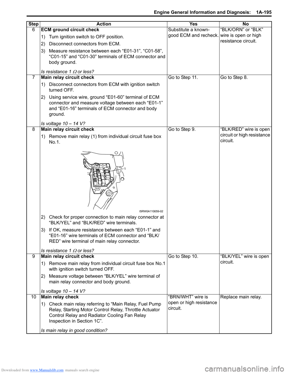
1) Remove main relay (1) from individual circuit fuse box
No.1.
2) Check for proper connection to main relay connector at
“BLK/YEL” and “BLK/RED” wire terminals.
3) If OK, measure resistance between each “E01-1” and
“E01-16” wire terminals of ECM connector and “BLK/
RED” wire terminal of main relay connector.
Is resistance 1
Ω or less?Go to Step 9. “BLK/RED” wire is open
circuit or high resistance
circuit.
9Main relay circuit check
1) Remove main relay from individual circuit fuse box No.1
with ignition switch turned OFF.
2) Measure voltage between “BLK/YEL” wire terminal of
main relay connector and body ground.
Is voltage 10 – 14 V?Go to Step 10. “BLK/YEL” wire is open
circuit.
10Main relay check
1) Check main relay referring to “Main Relay, Fuel Pump
Relay, Starting Motor Control Relay, Throttle Actuator
Control Relay and Radiator Cooling Fan Relay
Inspection in Section 1C”.
Is main relay in good condition?“BRN/WHT” wire is
open or high resistance
circuit.Replace main relay. Step Action Yes No
1
I5RW0A110059-02
Page 246 of 1556
Downloaded from www.Manualslib.com manuals search engine 1A-196 Engine General Information and Diagnosis:
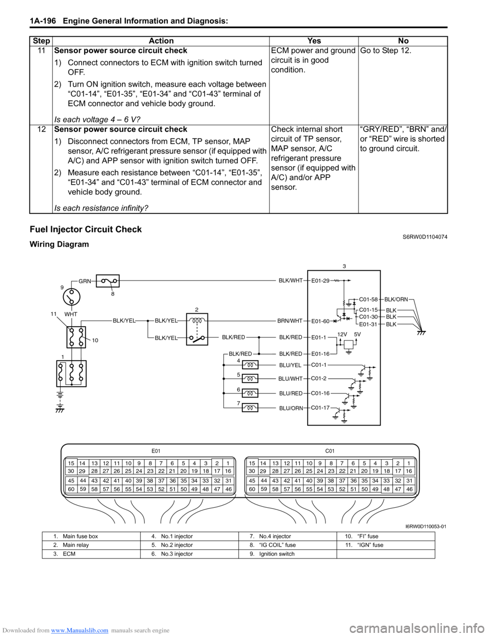
Fuel Injector Circuit CheckS6RW0D1104074
Wiring Diagram11Sensor power source circuit check
1) Connect connectors to ECM with ignition switch turned
OFF.
2) Turn ON ignition switch, measure each voltage between
“C01-14”, “E01-35”, “E01-34” and “C01-43” terminal of
ECM connector and vehicle body ground.
Is each voltage 4 – 6 V?ECM power and ground
circuit is in good
condition.Go to Step 12.
12Sensor power source circuit check
1) Disconnect connectors from ECM, TP sensor, MAP
sensor, A/C refrigerant pressure sensor (if equipped with
A/C) and APP sensor with ignition switch turned OFF.
2) Measure each resistance between “C01-14”, “E01-35”,
“E01-34” and “C01-43” terminal of ECM connector and
vehicle body ground.
Is each resistance infinity?Check internal short
circuit of TP sensor,
MAP sensor, A/C
refrigerant pressure
sensor (if equipped with
A/C) and/or APP
sensor.“GRY/RED”, “BRN” and/
or “RED” wire is shorted
to ground circuit. Step Action Yes No
BLK/WHT
BLK/RED
BLK/RED
WHTBLK/YELBLK/YEL
BLK/YEL
GRN
BRN/WHT
12V5V
9
2 83E01-29
E01-1
E01-60
10 11
E01C01
3 4
18 19 5 6 7 10 11
17 20
47 46 49 50 51 21 22
5216 259
24 14
29
55 57 54 53 59
60 582
26 27 28 15
30
56 4832 31 34 35 36 37 40 42 39 38 44
45 43 41 331 12 13
238 3 4
18 19 5 6 7 10 11
17 20
47 46 49 50 51 21 22
5216 259
24 14
29
55 57 54 53 59
60 582
26 27 28 15
30
56 4832 31 34 35 36 37 40 42 39 38 44
45 43 41 331 12 13
238
C01-1
C01-2
C01-16
C01-17
BLK/REDBLK/RED
BLU/YEL
BLU/RED
BLU/ORN
BLU/WHT
E01-16
4
5
6
71
C01-58
C01-15 C01-30
BLK/ORN
BLKBLKBLKE01-31
I6RW0D110053-01
1. Main fuse box 4. No.1 injector 7. No.4 injector 10. “FI” fuse
2. Main relay 5. No.2 injector 8. “IG COIL” fuse 11. “IGN” fuse
3. ECM 6. No.3 injector 9. Ignition switch
Page 248 of 1556
Downloaded from www.Manualslib.com manuals search engine 1A-198 Engine General Information and Diagnosis:
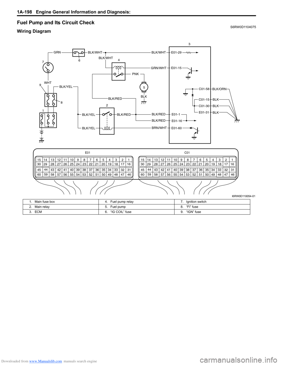
Fuel Pump and Its Circuit CheckS6RW0D1104075
Wiring Diagram
E01-1
E01-15
BLK/REDBLK/YEL
BLK/YEL
BLK/RED
E01-29BLK/WHT
GRN/WHT
BLK/WHT
BLK/WHT
PNK
BLK
WHT
GRN
C01-58
C01-15
C01-30
BLK/ORN
BLK
BLK
7
8 9643
25
E01C01
3 4
18 19 5 6 7 10 11
17 20
47 46 49 50 51 21 22
5216 259
24 14
29
55 57 54 53 59
60 582
26 27 28 15
30
56 4832 31 34 35 36 37 40 42 39 38 44
45 43 41 331 12 13
238 3 4
18 19 5 6 7 10 11
17 20
47 46 49 50 51 21 22
5216 259
24 14
29
55 57 54 53 59
60 582
26 27 28 15
30
56 4832 31 34 35 36 37 40 42 39 38 44
45 43 41 331 12 13
238
BLK/YEL
1
BLK
E01-16BLK/RED
BLK/RED
E01-31
BRN/WHTE01-60
I6RW0D110054-01
1. Main fuse box 4. Fuel pump relay 7. Ignition switch
2. Main relay 5. Fuel pump 8. “FI” fuse
3. ECM 6. “IG COIL” fuse 9. “IGN” fuse
Page 249 of 1556
Downloaded from www.Manualslib.com manuals search engine Engine General Information and Diagnosis: 1A-199
Troubleshooting
NOTE
• Before performed trouble shooting, be sure to read the “Precautions of ECM Circuit Inspection”.
• When measuring circuit voltage, resistance and/or pulse signal at ECM connector, connect the
special tool to ECM and/or the ECM connectors referring to “Inspection of ECM and Its Circuits”.
Step Action Yes No
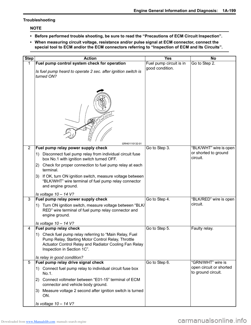
1Fuel pump control system check for operation
Is fuel pump heard to operate 2 sec. after ignition switch is
turned ON?Fuel pump circuit is in
good condition.Go to Step 2.
2Fuel pump relay power supply check
1) Disconnect fuel pump relay from individual circuit fuse
box No.1 with ignition switch turned OFF.
2) Check for proper connection to fuel pump relay at each
terminal.
3) If OK, turn ON ignition switch, measure voltage between
“BLK/WHT” wire terminal of fuel pump relay connector
and engine ground.
Is voltage 10 – 14 V?Go to Step 3. “BLK/WHT” wire is open
or shorted to ground
circuit.
3Fuel pump relay power supply check
1) Turn ON ignition switch, measure voltage between “BLK/
RED” wire terminal of fuel pump relay connector and
engine ground.
Is voltage 10 – 14 V?Go to Step 4. “BLK/RED” wire is open
circuit.
4Fuel pump relay check
1) Check fuel pump relay referring to “Main Relay, Fuel
Pump Relay, Starting Motor Control Relay, Throttle
Actuator Control Relay and Radiator Cooling Fan Relay
Inspection in Section 1C”.
Is relay in good condition?Go to Step 5. Faulty relay.
5Fuel pump relay drive signal check
1) Connect fuel pump relay to individual circuit fuse box
No.1.
2) Connect voltmeter between “E01-15” terminal of ECM
connector and vehicle body ground.
3) Measure voltage 2 second after ignition switch is turned
ON.
Is voltage 10 – 14 V?Go to Step 6. “GRN/WHT” wire is
open circuit or shorted
to ground circuit.
I2RH01110132-01
Page 253 of 1556
Downloaded from www.Manualslib.com manuals search engine Engine General Information and Diagnosis: 1A-203
Troubleshooting
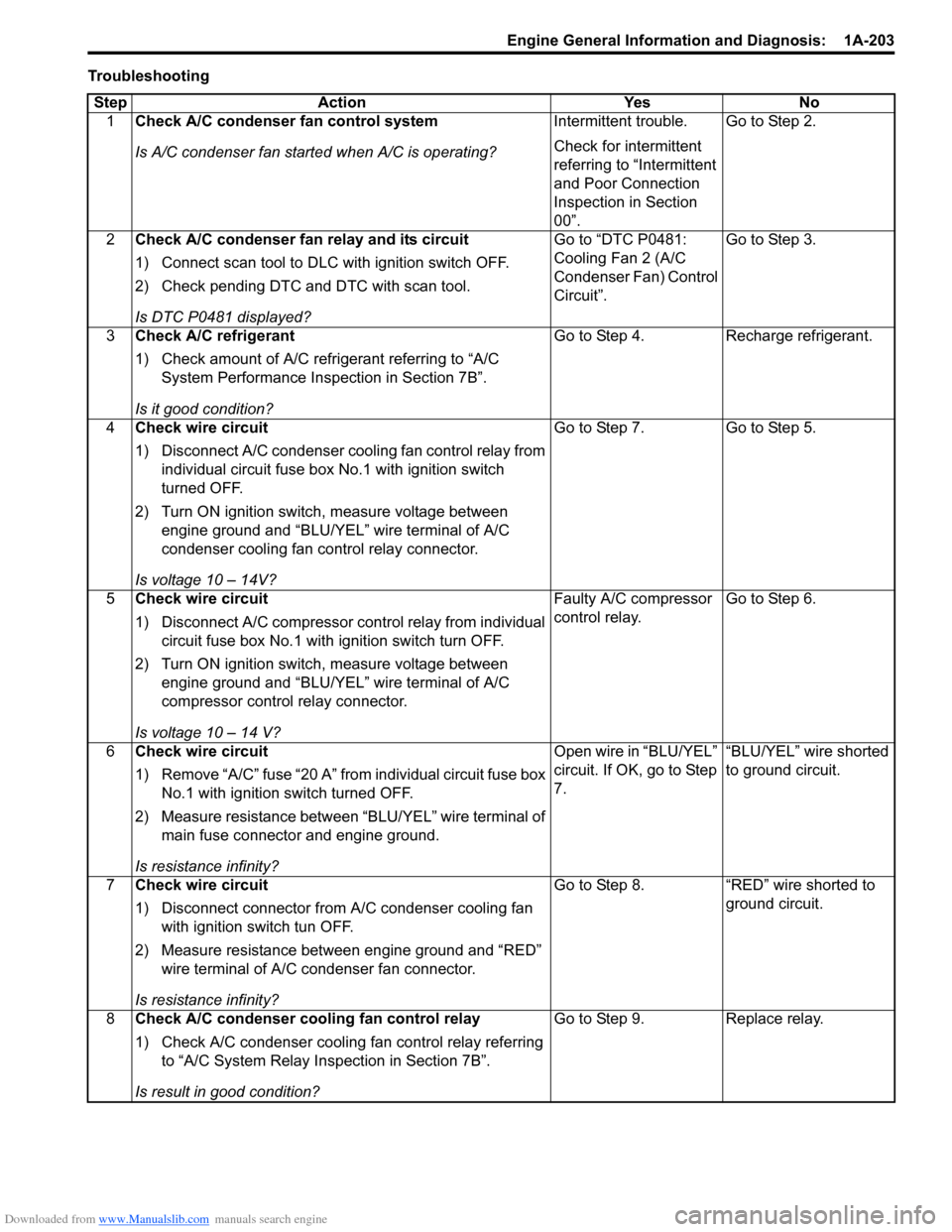
Step Action Yes No
1Check A/C condenser fan control system
Is A/C condenser fan started when A/C is operating?Intermittent trouble.
Check for intermittent
referring to “Intermittent
and Poor Connection
Inspection in Section
00”.Go to Step 2.
2Check A/C condenser fan relay and its circuit
1) Connect scan tool to DLC with ignition switch OFF.
2) Check pending DTC and DTC with scan tool.
Is DTC P0481 displayed?Go to “DTC P0481:
Cooling Fan 2 (A/C
Condenser Fan) Control
Circuit”.Go to Step 3.
3Check A/C refrigerant
1) Check amount of A/C refrigerant referring to “A/C
System Performance Inspection in Section 7B”.
Is it good condition?Go to Step 4. Recharge refrigerant.
4Check wire circuit
1) Disconnect A/C condenser cooling fan control relay from
individual circuit fuse box No.1 with ignition switch
turned OFF.
2) Turn ON ignition switch, measure voltage between
engine ground and “BLU/YEL” wire terminal of A/C
condenser cooling fan control relay connector.
Is voltage 10 – 14V?Go to Step 7. Go to Step 5.
5Check wire circuit
1) Disconnect A/C compressor control relay from individual
circuit fuse box No.1 with ignition switch turn OFF.
2) Turn ON ignition switch, measure voltage between
engine ground and “BLU/YEL” wire terminal of A/C
compressor control relay connector.
Is voltage 10 – 14 V?Faulty A/C compressor
control relay.Go to Step 6.
6Check wire circuit
1) Remove “A/C” fuse “20 A” from individual circuit fuse box
No.1 with ignition switch turned OFF.
2) Measure resistance between “BLU/YEL” wire terminal of
main fuse connector and engine ground.
Is resistance infinity?Open wire in “BLU/YEL”
circuit. If OK, go to Step
7.“BLU/YEL” wire shorted
to ground circuit.
7Check wire circuit
1) Disconnect connector from A/C condenser cooling fan
with ignition switch tun OFF.
2) Measure resistance between engine ground and “RED”
wire terminal of A/C condenser fan connector.
Is resistance infinity?Go to Step 8. “RED” wire shorted to
ground circuit.
8Check A/C condenser cooling fan control relay
1) Check A/C condenser cooling fan control relay referring
to “A/C System Relay Inspection in Section 7B”.
Is result in good condition?Go to Step 9. Replace relay.
Page 255 of 1556
Downloaded from www.Manualslib.com manuals search engine Engine General Information and Diagnosis: 1A-205
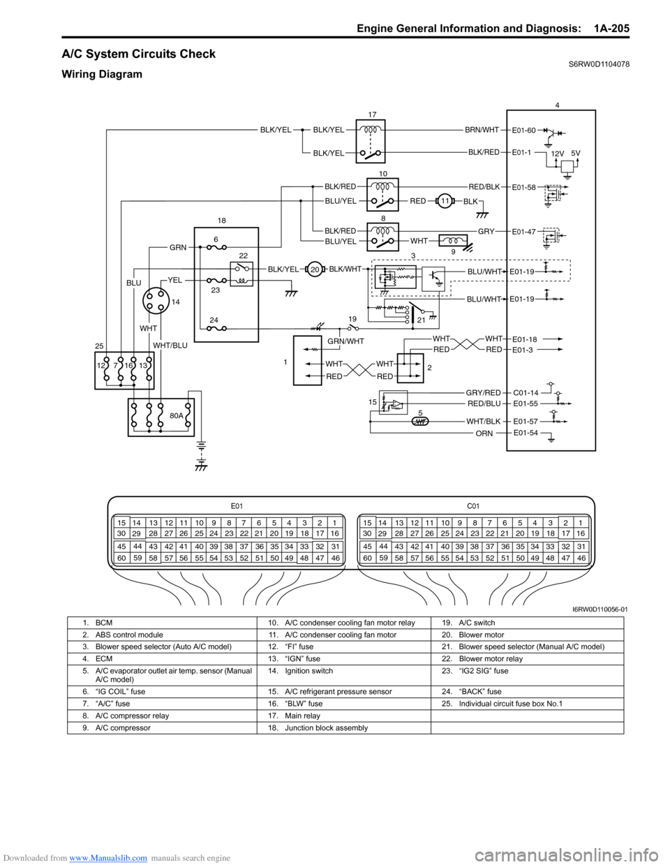
A/C System Circuits CheckS6RW0D1104078
Wiring Diagram
BLU/WHT
BLU/WHTE01-19
E01-19
21
E01C01
3 4
18 19 5 6 7 10 11
17 20
47 46 49 50 51 21 22
5216 259
24 14
29
55 57 54 53 59
60 582
26 27 28 15
30
56 4832 31 34 35 36 37 40 42 39 38 44
45 43 41 331 12 13
238 3 4
18 19 5 6 7 10 11
17 20
47 46 49 50 51 21 22
5216 259
24 14
29
55 57 54 53 59
60 582
26 27 28 15
30
56 4832 31 34 35 36 37 40 42 39 38 44
45 43 41 331 12 13
238
BLK/RED
BRN/WHT
12V5V
17
10
8
E01-1
E01-60
BLK/YEL
REDBLK11
WHT9
34
RED/BLK
BLK/REDE01-47
E01-58
BLU/YELGRY
19
2 1
20
5 15
WHT
RED
WHT
RED
WHT
RED
WHT
RED
E01-18E01-3
WHT/BLK
C01-14
E01-57
E01-54
E01-55RED/BLU
ORN
GRY/RED
BLK/YEL
GRN/WHT
BLK/WHT
WHT
1423
24
6
22 18
80A
1316 7 12
GRN
25
BLK/RED
BLU/YEL
YEL
WHT/BLU
BLK/YELBLK/YEL
BLU
I6RW0D110056-01
1. BCM 10. A/C condenser cooling fan motor relay 19. A/C switch
2. ABS control module 11. A/C condenser cooling fan motor 20. Blower motor
3. Blower speed selector (Auto A/C model) 12. “FI” fuse 21. Blower speed selector (Manual A/C model)
4. ECM 13. “IGN” fuse 22. Blower motor relay
5. A/C evaporator outlet air temp. sensor (Manual
A/C model)14. Ignition switch 23. “IG2 SIG” fuse
6. “IG COIL” fuse 15. A/C refrigerant pressure sensor 24. “BACK” fuse
7. “A/C” fuse 16. “BLW” fuse 25. Individual circuit fuse box No.1
8. A/C compressor relay 17. Main relay
9. A/C compressor 18. Junction block assembly
Page 259 of 1556
Downloaded from www.Manualslib.com manuals search engine Engine General Information and Diagnosis: 1A-209
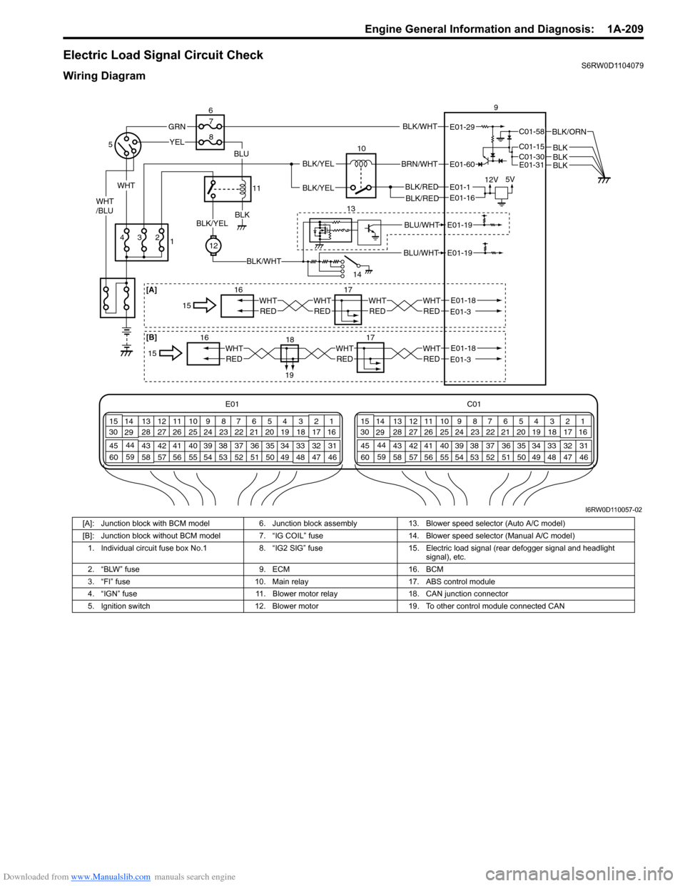
Electric Load Signal Circuit CheckS6RW0D1104079
Wiring Diagram
E01 C01
3 4
18 19 5 6 7 10 11
17 20
47 46 49 50 51 21 22
5216 259
24 14
29
55 57 54 53 59
60 582
26 27 28 15
30
56 4832 31 34 35 36 37 40 42 39 38 44
45 43 41 331 12 13
238 3 4
18 19 5 6 7 10 11
17 20
47 46 49 50 51 21 22
5216 259
24 14
29
55 57 54 53 59
60 582
26 27 28 15
30
56 4832 31 34 35 36 37 40 42 39 38 44
45 43 41 331 12 13
238
BLK/WHT
BLK/RED
WHT
BRN/WHT
12V5V
10
E01-29
E01-1
E01-60BLK/YEL
BLK/YEL
139BLK/REDE01-16
BLU/WHT
BLU/WHTE01-19
E01-19
14
3 4
YEL
2
12
BLK/WHT
BLKBLK/YEL
GRN
WHT/BLU
BLU
1 56
11 7
8
C01-58
C01-15C01-30
BLK/ORN
BLKBLKE01-31BLK
17 16
WHTREDE01-18E01-3 15WHTREDWHTREDWHTRED [A]
17
WHTRED
18E01-18E01-3 1615WHTREDWHTRED
[B]
19
I6RW0D110057-02
[A]: Junction block with BCM model 6. Junction block assembly 13. Blower speed selector (Auto A/C model)
[B]: Junction block without BCM model 7. “IG COIL” fuse 14. Blower speed selector (Manual A/C model)
1. Individual circuit fuse box No.1 8. “IG2 SIG” fuse 15. Electric load signal (rear defogger signal and headlight
signal), etc.
2. “BLW” fuse 9. ECM 16. BCM
3. “FI” fuse 10. Main relay 17. ABS control module
4. “IGN” fuse 11. Blower motor relay 18. CAN junction connector
5. Ignition switch 12. Blower motor 19. To other control module connected CAN
Page 261 of 1556
Downloaded from www.Manualslib.com manuals search engine Engine General Information and Diagnosis: 1A-211
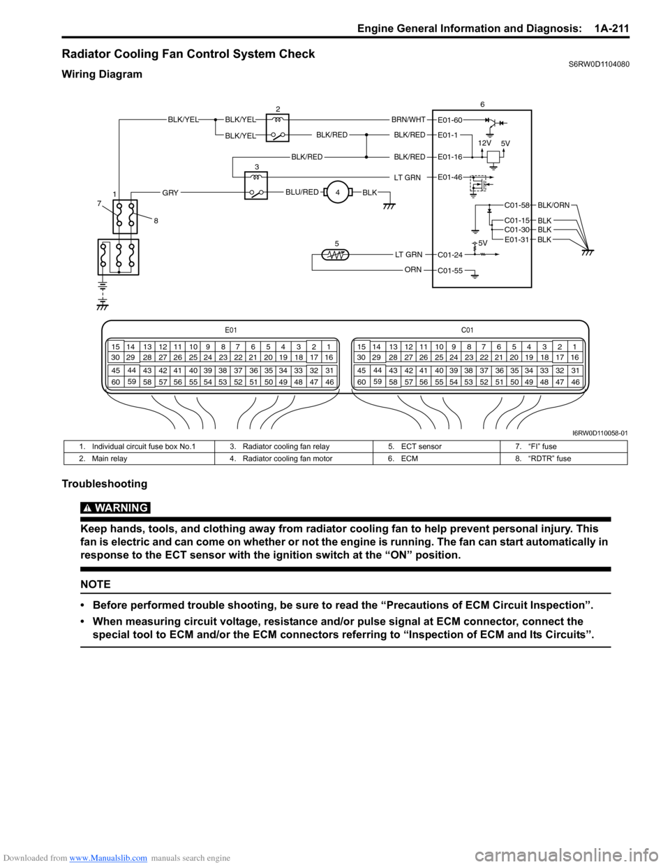
Radiator Cooling Fan Control System CheckS6RW0D1104080
Wiring Diagram
Troubleshooting
WARNING!
Keep hands, tools, and clothing away from radiator cooling fan to help prevent personal injury. This
fan is electric and can come on whether or not the engine is running. The fan can start automatically in
response to the ECT sensor with the ignition switch at the “ON” position.
NOTE
• Before performed trouble shooting, be sure to read the “Precautions of ECM Circuit Inspection”.
• When measuring circuit voltage, resistance and/or pulse signal at ECM connector, connect the
special tool to ECM and/or the ECM connectors referring to “Inspection of ECM and Its Circuits”.
E01C01
3 4
18 19 5 6 7 10 11
17 20
47 46 49 50 51 21 22
5216 259
24 14
29
55 57 54 53 59
60 582
26 27 28 15
30
56 4832 31 34 35 36 37 40 42 39 38 44
45 43 41 331 12 13
238 3 4
18 19 5 6 7 10 11
17 20
47 46 49 50 51 21 22
5216 259
24 14
29
55 57 54 53 59
60 582
26 27 28 15
30
56 4832 31 34 35 36 37 40 42 39 38 44
45 43 41 331 12 13
238
BLK/REDBLK/RED
BLK/YELBLK/YEL
BLK/YEL
BRN/WHT
12V
5V5V
26
E01-1
E01-60
C01-58
C01-15 C01-30
BLK/ORN
BLKBLK
BLK/RED
LT GRN
BLK/REDE01-16
E01-46
BLU/REDBLKGRY
LT GRN
ORN
C01-24
C01-55 3
4
5
E01-31 BLK
8 71
I6RW0D110058-01
1. Individual circuit fuse box No.1 3. Radiator cooling fan relay 5. ECT sensor 7. “FI” fuse
2. Main relay 4. Radiator cooling fan motor 6. ECM 8. “RDTR” fuse