main fuse box SUZUKI SX4 2006 1.G Service Service Manual
[x] Cancel search | Manufacturer: SUZUKI, Model Year: 2006, Model line: SX4, Model: SUZUKI SX4 2006 1.GPages: 1556, PDF Size: 37.31 MB
Page 623 of 1556

Downloaded from www.Manualslib.com manuals search engine ABS: 4E-18
WHTGRN
3
E08-2
E08-13REDWHT 5
4 12
9
E08-23
E08-26BLKBLK
76
BLK
REDWHTG241-7G241-10
G241-16
12V
E08-25E08-24
E08-9
WHT/REDWHT/BLU
GRN/ORN
9
REDWHTG05-1G05-3
REDWHTG05-4G05-2
9
2
1
13
G241-31
RED/BLK
8
11+BBBG
G1
12V
E08-1614BLU 10
[C]E08
1
2
3
4
5
6
7 12
13
14
15
16
17
18
19
20
21
228
9
10
11
23
24
25
26
G05 [E]
1 2 3 4 765 8 9 10 11 14 15 16
36 34 33 32 3135 24 23 2122 28 27 2526 37 39 38 4018 17 13 12 19 20
30 29
G241 [D]
132 4 5 6 7 8 9 10111213141516
17 1918 20 2122 23 24 25 26 27 28 29 30 31 32 [B]
I6RW0D450003-02
[A]: Junction block with BCM 3. Ignition switch 10. BCM
[B]: Junction block without BCM 4. Junction block assembly 11. Data link connector (DLC)
[C]: ABS control module connector (viewed from
terminal side)5. Combination meter 12. ABS hydraulic unit / control module assembly
[D]: BCM connector (viewed from harness side) 6.ABS warning light 13. CAN junction connector
[E]: Combination meter connector (viewed from
terminal side)7. EBD warning light (brake
warning light)14. To TCM (A/T model), BCM, 4WD control module, P/S control
module (electric P/S model), HVAC control module (auto A/C
model) and SDM
1. Battery 8. Light driver module
2. Main fuse box 9. CAN driver
Page 625 of 1556
Downloaded from www.Manualslib.com manuals search engine ABS: 4E-20
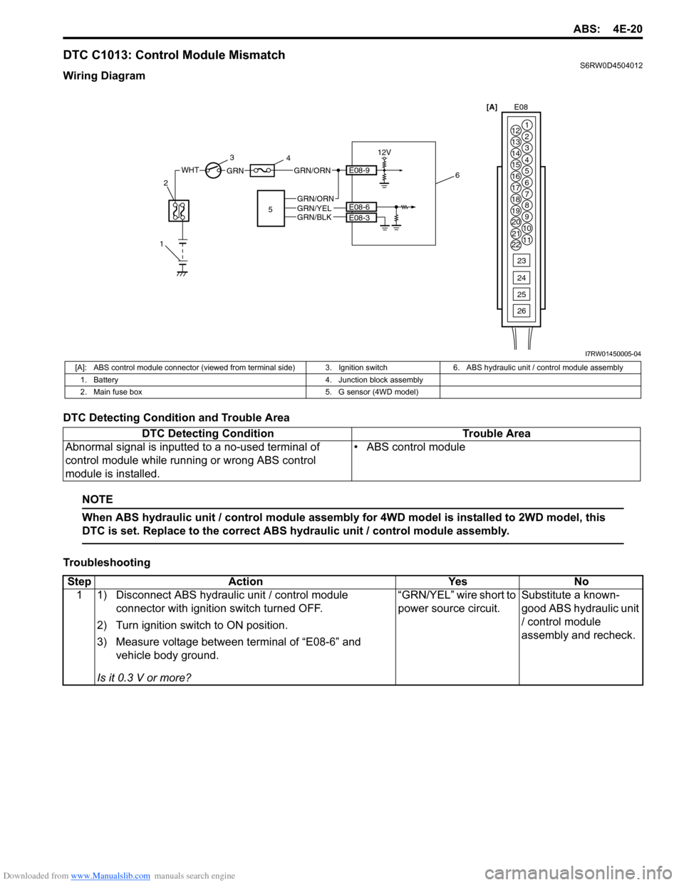
DTC C1013: Control Module MismatchS6RW0D4504012
Wiring Diagram
DTC Detecting Condition and Trouble Area
NOTE
When ABS hydraulic unit / control module assembly for 4WD model is installed to 2WD model, this
DTC is set. Replace to the correct ABS hydraulic unit / control module assembly.
Troubleshooting
WHTGRN
123
4
E08-3 E08-6GRN/BLKGRN/YELGRN/ORN
12V
E08-9GRN/ORN
56[A]E08
1
2
3
4
5
6
7 12
13
14
15
16
17
18
19
20
21
228
9
10
11
23
24
25
26
I7RW01450005-04
[A]: ABS control module connector (viewed from terminal side) 3. Ignition switch 6. ABS hydraulic unit / control module assembly
1. Battery 4. Junction block assembly
2. Main fuse box 5. G sensor (4WD model)
DTC Detecting Condition Trouble Area
Abnormal signal is inputted to a no-used terminal of
control module while running or wrong ABS control
module is installed.• ABS control module
Step Action Yes No
1 1) Disconnect ABS hydraulic unit / control module
connector with ignition switch turned OFF.
2) Turn ignition switch to ON position.
3) Measure voltage between terminal of “E08-6” and
vehicle body ground.
Is it 0.3 V or more?“GRN/YEL” wire short to
power source circuit.Substitute a known-
good ABS hydraulic unit
/ control module
assembly and recheck.
Page 627 of 1556
Downloaded from www.Manualslib.com manuals search engine ABS: 4E-22
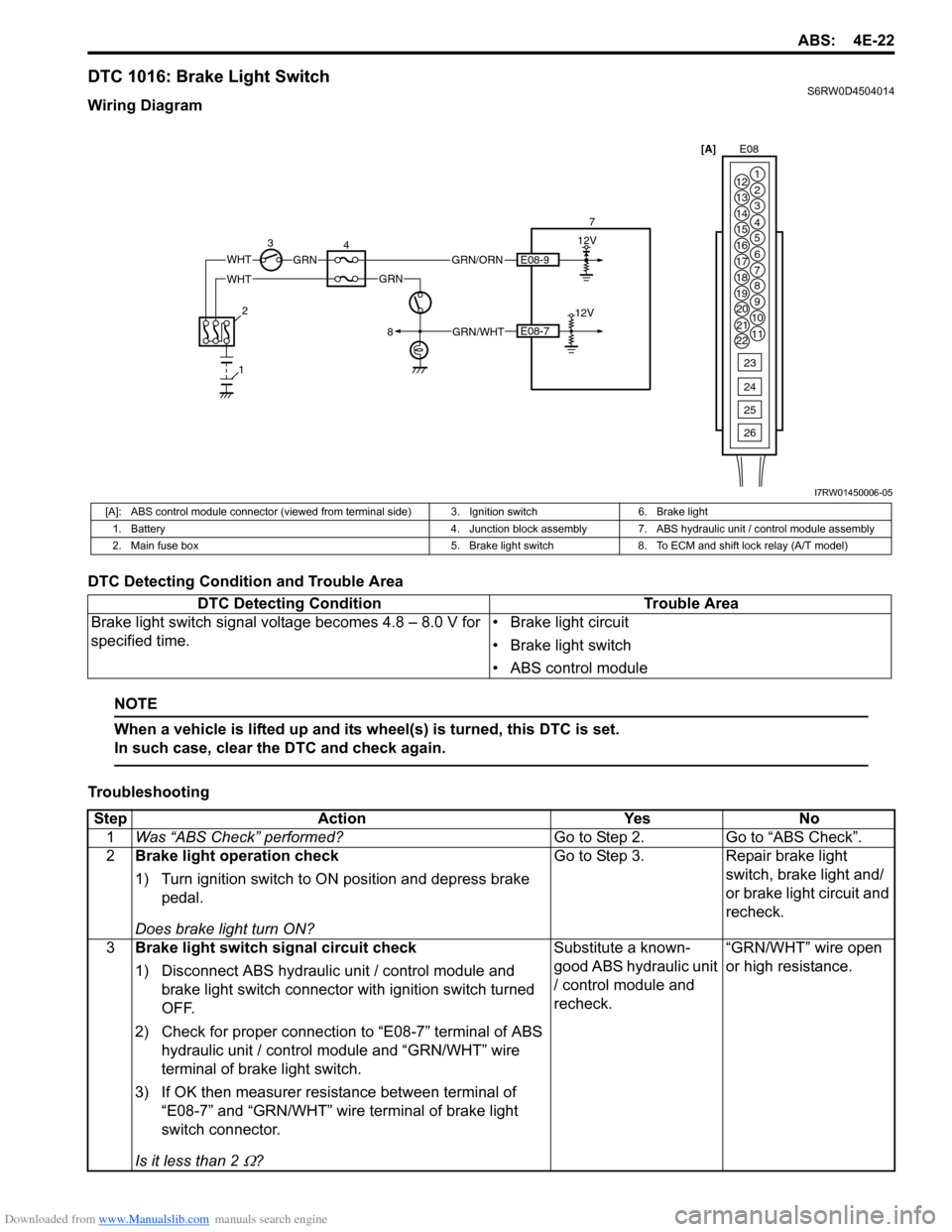
DTC 1016: Brake Light SwitchS6RW0D4504014
Wiring Diagram
DTC Detecting Condition and Trouble Area
NOTE
When a vehicle is lifted up and its wheel(s) is turned, this DTC is set.
In such case, clear the DTC and check again.
Troubleshooting
WHTGRN
34 712V
E08-7
E08-9GRN/ORN
2
8
112V
GRN/WHT
WHTGRN[A]E08
1
2
3
4
5
6
7 12
13
14
15
16
17
18
19
20
21
228
9
10
11
23
24
25
26
I7RW01450006-05
[A]: ABS control module connector (viewed from terminal side) 3. Ignition switch 6. Brake light
1. Battery 4. Junction block assembly 7. ABS hydraulic unit / control module assembly
2. Main fuse box 5. Brake light switch 8. To ECM and shift lock relay (A/T model)
DTC Detecting Condition Trouble Area
Brake light switch signal voltage becomes 4.8 – 8.0 V for
specified time.• Brake light circuit
• Brake light switch
• ABS control module
Step Action Yes No
1Was “ABS Check” performed?Go to Step 2. Go to “ABS Check”.
2Brake light operation check
1) Turn ignition switch to ON position and depress brake
pedal.
Does brake light turn ON?Go to Step 3. Repair brake light
switch, brake light and/
or brake light circuit and
recheck.
3Brake light switch signal circuit check
1) Disconnect ABS hydraulic unit / control module and
brake light switch connector with ignition switch turned
OFF.
2) Check for proper connection to “E08-7” terminal of ABS
hydraulic unit / control module and “GRN/WHT” wire
terminal of brake light switch.
3) If OK then measurer resistance between terminal of
“E08-7” and “GRN/WHT” wire terminal of brake light
switch connector.
Is it less than 2
Ω?Substitute a known-
good ABS hydraulic unit
/ control module and
recheck.“GRN/WHT” wire open
or high resistance.
Page 628 of 1556
Downloaded from www.Manualslib.com manuals search engine 4E-23 ABS:
DTC C1021 / C1022 / C1025 / C1026 / C1031 / C1032 / C1035 / C1036: Wheel Speed Sensor Circuit /
Sensor or Encoder
S6RW0D4504015
DTC C1021 / C1025 / C1031 / C1035: Right-Front / Left-Front / Right-Rear / Left-Rear Wheel Speed
Sensor Circuit
DTC C1022 / C1026 / C1032 / C1036: Right-Front / Left-Front / Right-Rear / Left-Rear Wheel Speed
Sensor or Encoder
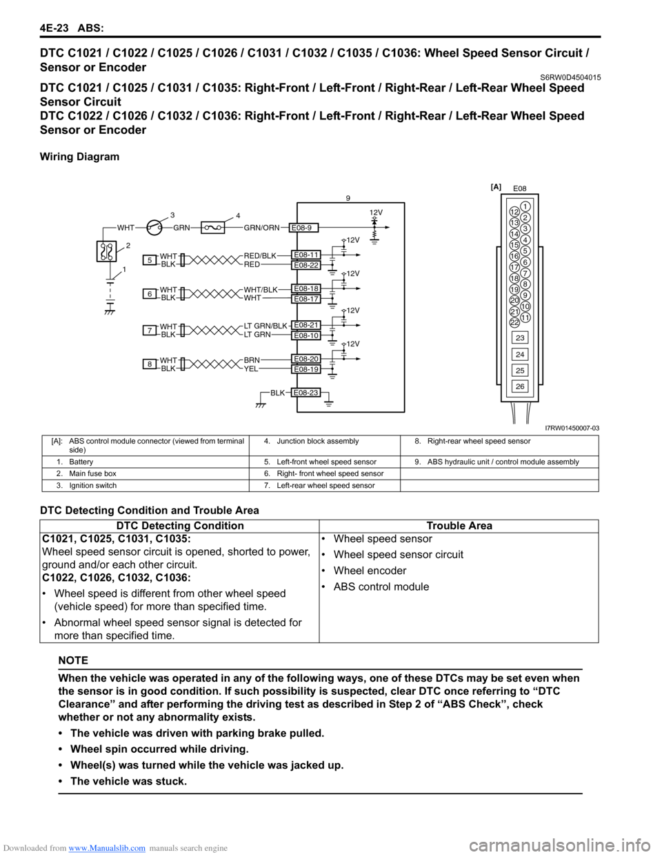
Wiring Diagram
DTC Detecting Condition and Trouble Area
NOTE
When the vehicle was operated in any of the following ways, one of these DTCs may be set even when
the sensor is in good condition. If such possibility is suspected, clear DTC once referring to “DTC
Clearance” and after performing the driving test as described in Step 2 of “ABS Check”, check
whether or not any abnormality exists.
• The vehicle was driven with parking brake pulled.
• Wheel spin occurred while driving.
• Wheel(s) was turned while the vehicle was jacked up.
• The vehicle was stuck.
E08 [A]
1
2
3
4
5
6
7 12
13
14
15
16
17
18
19
20
21
228
9
10
11
23
24
25
26
WHTGRNGRN/ORN
3
4
E08-9
9
12V
8
7
6
5
BLKWHT
BLKWHT
REDRED/BLK
LT GRN/BLKLT GRN
E08-22 E08-11
E08-10 E08-21
E08-23BLK
12V
12V
12V
12V
BLKWHT
BLKWHTWHTWHT/BLK
E08-17 E08-18
YELBRN
E08-19 E08-20
12
I7RW01450007-03
[A]: ABS control module connector (viewed from terminal
side)4. Junction block assembly 8. Right-rear wheel speed sensor
1. Battery 5. Left-front wheel speed sensor 9. ABS hydraulic unit / control module assembly
2. Main fuse box 6. Right- front wheel speed sensor
3. Ignition switch 7. Left-rear wheel speed sensor
DTC Detecting Condition Trouble Area
C1021, C1025, C1031, C1035:
Wheel speed sensor circuit is opened, shorted to power,
ground and/or each other circuit.
C1022, C1026, C1032, C1036:
• Wheel speed is different from other wheel speed
(vehicle speed) for more than specified time.
• Abnormal wheel speed sensor signal is detected for
more than specified time.• Wheel speed sensor
• Wheel speed sensor circuit
• Wheel encoder
• ABS control module
Page 631 of 1556

Downloaded from www.Manualslib.com manuals search engine ABS: 4E-26
DTC C1041 / C1042 / C1045 / C1046 / C1051 / C1052 / C1055 / C1056: Inlet / Outlet SolenoidS6RW0D4504017
DTC C1041 / C1045 / C1051 / C1055: Right-Front / Left-Front / Right-Rear / Left- Rear Inlet Solenoid
DTC C1042 / C1046 / C1052 / C1056: Right-Front / Left-Front / Right-Rear / Left- Rear Outlet Solenoid
Wiring Diagram
DTC Detecting Condition and Trouble Area
DTC Troubleshooting
WHT/BLU
1 2
5
3
BLK
E08-24
E08-23
6 4
E08 [A]
1
2
3
4
5
6
7 12
13
14
15
16
17
18
19
20
21
228
9
10
11
23
24
25
26
I7RW01450008-02
[A]: ABS control module assembly connector (viewed from terminal side) 4. ABS hydraulic unit / control module assembly
1. Battery5. Solenoid valve power supply driver (transistor)
2. Main fuse box6. Solenoid valve driver
3. Solenoid valve
DTC Detecting Condition Trouble Area
DTC C1041, C1042, C1045, C1046, C1051, C1052,
C1055, C1056:
• Solenoid valve circuit is opened, shorted to power,
ground and/or each valve in ABS hydraulic unit / control
module assembly.
• Mismatching solenoid output and solenoid monitor is
detected.• ABS control module
Step Action Yes No
1Was “ABS Check” performed?Go to Step 2. Go to “ABS Check”.
2ABS hydraulic unit / control module power source
circuit check
1) Turn ignition switch to OFF position.
2) Disconnect ABS hydraulic unit / control module
connector.
3) Check for proper connection to ABS hydraulic unit /
control module connector at terminal “E08-24” and “E08-
23”.
4) If OK, then measure voltage between terminal “E08-24”
of module connector and “E08-23”.
Is it 10 – 14 V?Substitute a known-
good ABS hydraulic unit
/ control module
assembly and recheck.“WHT/BLU” or “BLK”
circuit open or high
resistance.
Page 632 of 1556
Downloaded from www.Manualslib.com manuals search engine 4E-27 ABS:
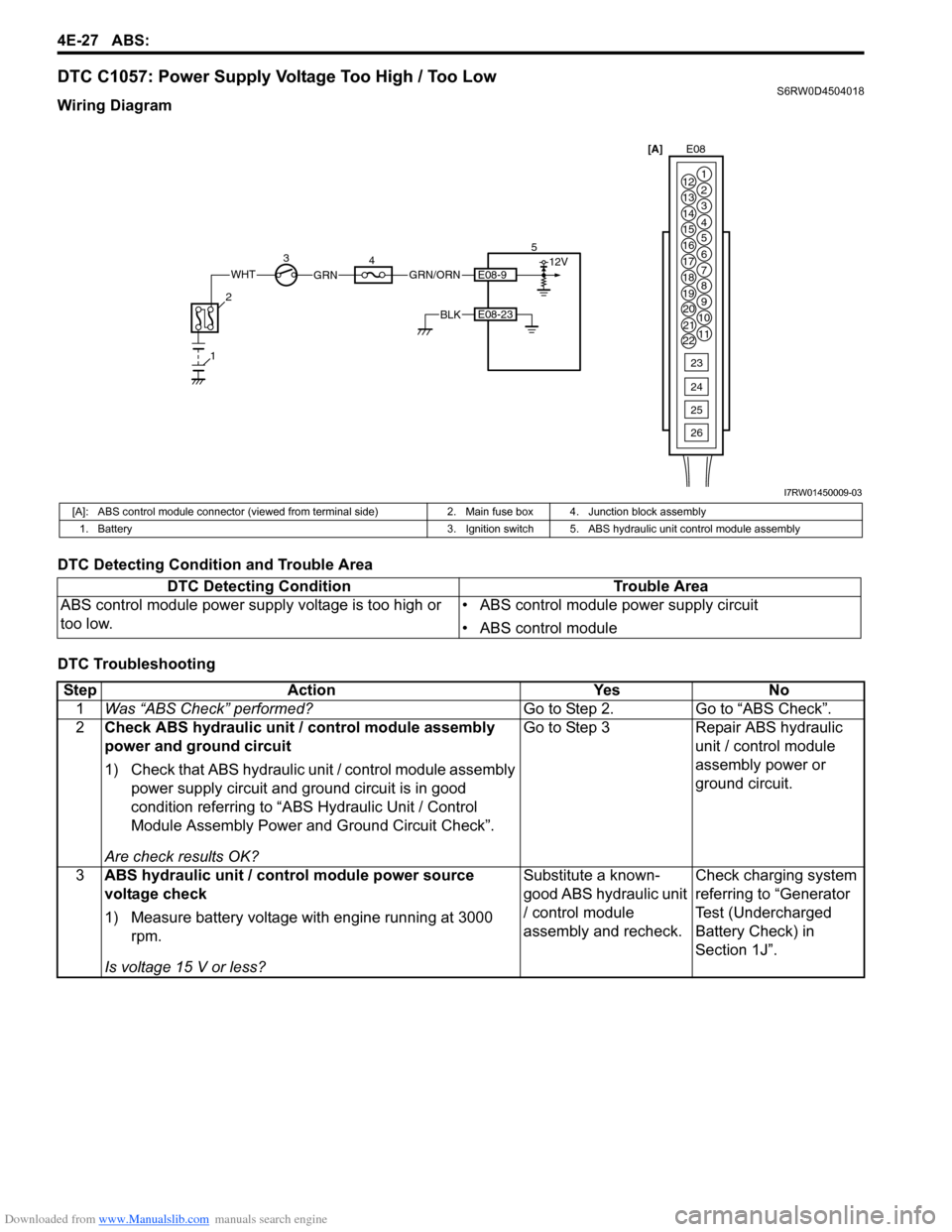
DTC C1057: Power Supply Voltage Too High / Too LowS6RW0D4504018
Wiring Diagram
DTC Detecting Condition and Trouble Area
DTC Troubleshooting
WHTGRN
34 5
E08-23BLK
12VE08-9GRN/ORN
2
1
[A]E08
1
2
3
4
5
6
7 12
13
14
15
16
17
18
19
20
21
228
9
10
11
23
24
25
26
I7RW01450009-03
[A]: ABS control module connector (viewed from terminal side) 2. Main fuse box 4. Junction block assembly
1. Battery 3. Ignition switch 5. ABS hydraulic unit control module assembly
DTC Detecting Condition Trouble Area
ABS control module power supply voltage is too high or
too low.• ABS control module power supply circuit
• ABS control module
Step Action Yes No
1Was “ABS Check” performed?Go to Step 2. Go to “ABS Check”.
2Check ABS hydraulic unit / control module assembly
power and ground circuit
1) Check that ABS hydraulic unit / control module assembly
power supply circuit and ground circuit is in good
condition referring to “ABS Hydraulic Unit / Control
Module Assembly Power and Ground Circuit Check”.
Are check results OK?Go to Step 3 Repair ABS hydraulic
unit / control module
assembly power or
ground circuit.
3ABS hydraulic unit / control module power source
voltage check
1) Measure battery voltage with engine running at 3000
rpm.
Is voltage 15 V or less?Substitute a known-
good ABS hydraulic unit
/ control module
assembly and recheck.Check charging system
referring to “Generator
Test (Undercharged
Battery Check) in
Section 1J”.
Page 633 of 1556

Downloaded from www.Manualslib.com manuals search engine ABS: 4E-28
DTC C1061: Pump Motor CircuitS6RW0D4504019
Wiring Diagram
DTC Detecting Condition and Trouble Area
DTC Troubleshooting
WHT/RED
1 2
5
M
3
4
12VE08-25
E08-26BLKE08 [A]
1
2
3
4
5
6
7 12
13
14
15
16
17
18
19
20
21
228
9
10
11
23
24
25
26
I7RW01450010-02
[A]: ABS control module connector (viewed from terminal side) 3. Pump motor driver (transistor)
1. Battery 4. ABS pump motor
2. Main fuse box 5. ABS hydraulic unit / control module assembly
DTC Detecting Condition Trouble Area
• Defective pump motor and/or motor power supply
voltage is too low.
• Pump motor circuit in ABS control module is opened,
shorted to power or ground circuit.• Pump Motor and/or Motor Driver power supply circuit
• ABS control module
Step Action Yes No
1Was “ABS Check” performed?Go to Step 2. Go to “ABS Check”.
2Check ABS hydraulic unit / control module assembly
power and ground circuit
1) Check that ABS hydraulic unit / control module assembly
power supply circuit and ground circuit is in good
condition referring to “ABS Hydraulic Unit / Control
Module Assembly Power and Ground Circuit Check”.
Are check results OK?Substitute a known-
good ABS hydraulic unit
/ control module
assembly and recheck.Repair ABS hydraulic
unit / control module
assembly power or
ground circuit.
Page 634 of 1556
Downloaded from www.Manualslib.com manuals search engine 4E-29 ABS:
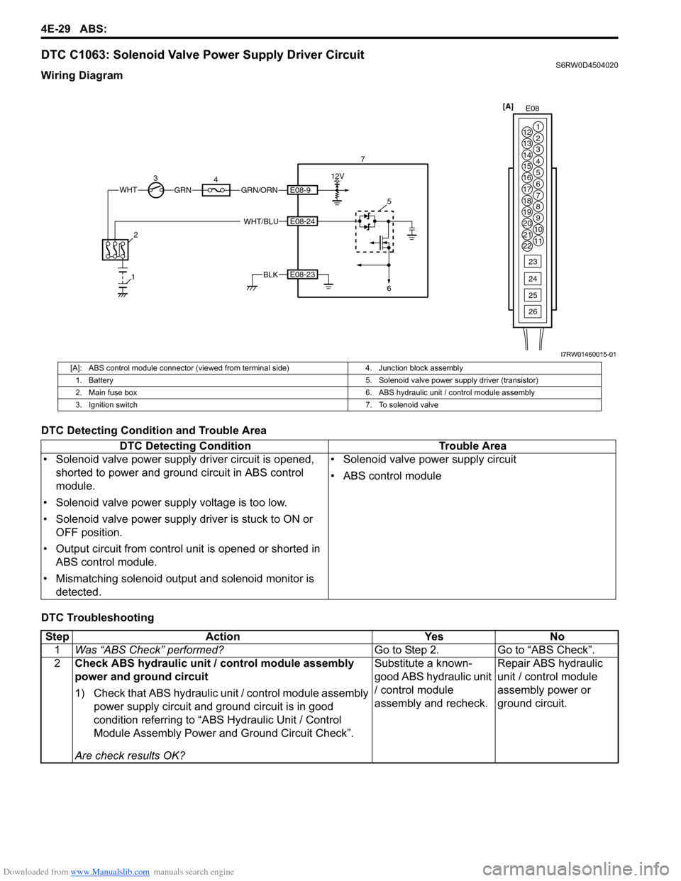
DTC C1063: Solenoid Valve Power Supply Driver CircuitS6RW0D4504020
Wiring Diagram
DTC Detecting Condition and Trouble Area
DTC Troubleshooting
E08 [A]
1
2
3
4
5
6
7 12
13
14
15
16
17
18
19
20
21
228
9
10
11
23
24
25
26
WHTGRN 34 7
E08-23BLK12V
E08-9GRN/ORN
2
1
WHT/BLU5E08-24
6
I7RW01460015-01
[A]: ABS control module connector (viewed from terminal side) 4. Junction block assembly
1. Battery5. Solenoid valve power supply driver (transistor)
2. Main fuse box 6. ABS hydraulic unit / control module assembly
3. Ignition switch 7. To solenoid valve
DTC Detecting Condition Trouble Area
• Solenoid valve power supply driver circuit is opened,
shorted to power and ground circuit in ABS control
module.
• Solenoid valve power supply voltage is too low.
• Solenoid valve power supply driver is stuck to ON or
OFF position.
• Output circuit from control unit is opened or shorted in
ABS control module.
• Mismatching solenoid output and solenoid monitor is
detected.• Solenoid valve power supply circuit
• ABS control module
Step Action Yes No
1Was “ABS Check” performed?Go to Step 2. Go to “ABS Check”.
2Check ABS hydraulic unit / control module assembly
power and ground circuit
1) Check that ABS hydraulic unit / control module assembly
power supply circuit and ground circuit is in good
condition referring to “ABS Hydraulic Unit / Control
Module Assembly Power and Ground Circuit Check”.
Are check results OK?Substitute a known-
good ABS hydraulic unit
/ control module
assembly and recheck.Repair ABS hydraulic
unit / control module
assembly power or
ground circuit.
Page 635 of 1556
Downloaded from www.Manualslib.com manuals search engine ABS: 4E-30
DTC C1071: Control Module Internal DefectS6RW0D4504021
DTC Detecting Condition and Trouble Area
DTC Troubleshooting
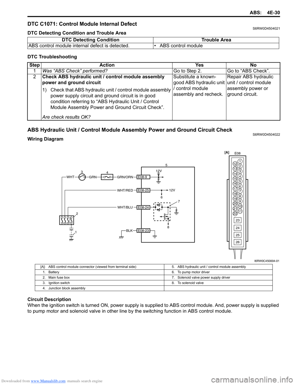
ABS Hydraulic Unit / Control Module Assembly Power and Ground Circuit CheckS6RW0D4504022
Wiring Diagram
Circuit Description
When the ignition switch is turned ON, power supply is supplied to ABS control module. And, power supply is supplied
to pump motor and solenoid valve in other line by the switching function in ABS control module. DTC Detecting Condition Trouble Area
ABS control module internal defect is detected. • ABS control module
Step Action Yes No
1Was “ABS Check” performed?Go to Step 2. Go to “ABS Check”.
2Check ABS hydraulic unit / control module assembly
power and ground circuit
1) Check that ABS hydraulic unit / control module assembly
power supply circuit and ground circuit is in good
condition referring to “ABS Hydraulic Unit / Control
Module Assembly Power and Ground Circuit Check”.
Are check results OK?Substitute a known-
good ABS hydraulic unit
/ control module
assembly and recheck.Repair ABS hydraulic
unit / control module
assembly power or
ground circuit.
E08 [A]
1
2
3
4
5
6
7 12
13
14
15
16
17
18
19
20
21
228
9
10
11
23
24
25
26
WHTGRN
35
6
7
84
E08-23BLK
12V
E08-25
E08-24
E08-9
WHT/RED
WHT/BLU
GRN/ORN
2
1
12V
I6RW0C450004-01
[A]: ABS control module connector (viewed from terminal side) 5. ABS hydraulic unit / control module assembly
1. Battery6. To pump motor driver
2. Main fuse box 7. Solenoid valve power supply driver
3. Ignition switch 8. To solenoid valve
4. Junction block assembly
Page 884 of 1556
![SUZUKI SX4 2006 1.G Service Service Manual Downloaded from www.Manualslib.com manuals search engine 6C-4 Power Assisted Steering System:
Schematic and Routing Diagram
EPS System Wiring Circuit DiagramS6RW0D6302001
[A]
123
45
3 21
4
567
8
9 11 SUZUKI SX4 2006 1.G Service Service Manual Downloaded from www.Manualslib.com manuals search engine 6C-4 Power Assisted Steering System:
Schematic and Routing Diagram
EPS System Wiring Circuit DiagramS6RW0D6302001
[A]
123
45
3 21
4
567
8
9 11](/img/20/7612/w960_7612-883.png)
Downloaded from www.Manualslib.com manuals search engine 6C-4 Power Assisted Steering System:
Schematic and Routing Diagram
EPS System Wiring Circuit DiagramS6RW0D6302001
[A]
123
45
3 21
4
567
8
9 11
10 12 13
141516
17 18 19201
2
[B]
1
2
[C] [D]
10 9 8 7654 3 21
16 15 14 13 12 11
26 25 24 2322 21 20 19 18 17
32 31 30 29 28 27
[F][E]
12
BRN RED/
BLU GRY LT GRN/
BLK
BLK
RED
WHT GRN
BLK
E11-1
E11-5
E11-14
E11-12
[J]:E01-44E01-4
[J]:E01-27E01-26
E12-1
E12-2
E11-10E11-8
E11-9
E11-19
E13-1 GRN
GRY
GRN
WHT
G241-25G241-31
RED/BLK
11
12
1314 3 18
20
21
7 19
4 12
22
12V
E13-2BLK
9V
REDE11-20
12V
12V
E61-2
E61-1
610
55
5V
8
E11-115V
PPL
E11-4
9
23
+BB
BLU/
WHTE04-9
1524YELE11-18E31-5
E31-2
E31-39V
3V
E31-4
E31-1IG11617
C07-25
[H]
[G]
G04-15
[I]:G04-22
25L313-3
[I]
I6RW0D630001-01
[A]: P/S control module connector No.1 “E11” (viewed from harness side) 3. Junction block assembly 15. BCM
[B]: P/S control module connector No.2 “E13” (viewed from harness side) 4. Main fuse 16. Output shaft speed sensor
[C]: P/S control module connector No.3 “E12” (viewed from harness side) 5. Front (left/right) wheel speed sensor 17. TCM
[D]: Combination meter connector “G241” (viewed from harness side) 6. ABS control module 18. Individual circuit fuse box No.1
[E]: Torque sensor connector “E31” (viewed from harness side) 7. Combination meter 19. “IGN” fuse
[F]: Motor connector “E61” (viewed from harness side) 8. “EPS” warning light 20. “P/S” fuse
[G]: M/T model 9. Data link connector (DLC) 21. “IG1 SIG” fuse
[H]: A/T model 10. ECM 22. “MTR” fuse
[I]: Junction block without BCM model (Taiwan model) 11. P/S control module 23. To ABS control module
[J]: M15A engine with 4A/T equipped with slip control model (Hong Kong
model)12. P/S motor 24. To HVAC control module
1. Main fuse box 13. Shield 25. To SDM
2. Ignition switch 14. Torque sensor (built into steering gear case)