rear assembly SUZUKI SX4 2006 1.G Service Owner's Manual
[x] Cancel search | Manufacturer: SUZUKI, Model Year: 2006, Model line: SX4, Model: SUZUKI SX4 2006 1.GPages: 1556, PDF Size: 37.31 MB
Page 477 of 1556
Downloaded from www.Manualslib.com manuals search engine Table of Contents 3- i
3
Section 3
CONTENTS
Driveline / Axle
Precautions ................................................. 3-1
Precautions............................................................. 3-1
Precautions on Driveline / Axle ............................. 3-1
Drive Shaft / Axle ..................................... 3A-1
Front ......................................................................... 3A-1
General Description ............................................. 3A-1
Front Drive Shaft Construction ............................ 3A-1
Component Location ........................................... 3A-1
Front Drive Shaft Assembly Components
Location ............................................................ 3A-1
Diagnostic Information and Procedures ............ 3A-2
Front Drive Shaft Symptom Diagnosis ................ 3A-2
Repair Instructions .............................................. 3A-2
Front Drive Shaft Components ........................... 3A-2
Front Drive Shaft Assembly On-Vehicle
Inspection.......................................................... 3A-3
Front Drive Shaft Assembly Removal and
Installation ......................................................... 3A-3
Front Drive Shaft Disassembly and
Reassembly ...................................................... 3A-4
Center Shaft and Center Bearing Support
Disassembly and Reassembly (If Equipped) .. 3A-12
Specifications..................................................... 3A-13
Tightening Torque Specifications ...................... 3A-13
Special Tools and Equipment ........................... 3A-14
Recommended Service Material ....................... 3A-14
Special Tool ...................................................... 3A-14
Rear ........................................................................ 3A-15
General Description ........................................... 3A-15
Rear Drive Shaft Construction .......................... 3A-15
Repair Instructions ............................................ 3A-15
Rear Drive Shaft Components .......................... 3A-15
Rear Drive Shaft Assembly Removal and
Installation ....................................................... 3A-16
Rear Drive Shaft Disassembly and
Reassembly .................................................... 3A-16
Specifications..................................................... 3A-18
Tightening Torque Specifications ...................... 3A-18
Special Tools and Equipment ........................... 3A-18
Recommended Service Material ....................... 3A-18
Special Tool ...................................................... 3A-18
Differential ................................................ 3B-1
Precautions...........................................................3B-1
Precaution for Rear Differential Oil Leakage....... 3B-1
Precautions in Diagnosing Trouble ..................... 3B-1
General Description .............................................3B-2
Rear Differential Description ............................... 3B-2
Coupling Description ........................................... 3B-2
4WD Control System Components ..................... 3B-3
4WD Control System Description........................ 3B-4
Function of 4WD Control System Component .... 3B-4
4WD Control System Wiring Circuit Diagram...... 3B-5
Terminal Arrangement of 4WD Control
Module .............................................................. 3B-5
Input / Output Signal Table of 4WD Control
Module .............................................................. 3B-6
On-Board Diagnostic System Description ........... 3B-6
CAN Communication System Description........... 3B-7
Diagnostic Information and Procedures ............3B-8
4WD Control System Check ............................... 3B-8
4WD Position Indicator Operation Check.......... 3B-10
4WD Control System Operation Inspection ...... 3B-10
Visual Inspection ............................................... 3B-11
DTC Check........................................................ 3B-11
DTC Clearance ................................................. 3B-11
DTC Table ......................................................... 3B-12
Fail-Safe Table .................................................. 3B-12
Scan Tool Data ................................................. 3B-13
Rear Differential Symptom Diagnosis ............... 3B-14
4WD Control Symptom Diagnosis..................... 3B-14
4WD Position Indicator Does Not Come ON at
Ignition Switch ON but Engine Stops .............. 3B-15
4WD Position Indicator Remains ON Steady
at Ignition Switch ON....................................... 3B-16
DTC C1240: 4WD Control Module Power
Supply Circuit Malfunction............................... 3B-17
DTC C1243: Internal Circuit Malfunction of
4WD Control Module ....................................... 3B-18
DTC C1250: Coupling Air Temperature
Sensor Circuit Open ........................................ 3B-19
DTC C1251: Coupling Air Temperature
Sensor Circuit Short ........................................ 3B-21
DTC C1252: Coupling Assembly Circuit Open .. 3B-22
DTC C1253: Coupling Assembly Circuit Short .. 3B-24
DTC C1254: 2WD/4WD Switch Malfunction ..... 3B-25
DTC U0073: Control Module Communication
Bus Off ............................................................ 3B-27
Page 478 of 1556
Downloaded from www.Manualslib.com manuals search engine 3-ii Table of Contents
DTC U0100: Lost Communication with ECM .... 3B-27
DTC U0121: Lost Communication with ABS /
ESP® Control Module..................................... 3B-27
DTC U0155: Lost Communication with
Instrument Panel Cluster (IPC) Control
Module ............................................................ 3B-27
Inspection of 4WD Control Module and Its
Circuits ............................................................ 3B-27
Repair Instructions ............................................3B-30
Rear Differential Oil Level Check ...................... 3B-30
Rear Differential Oil Change ............................. 3B-30
2WD/4WD Switch Removal and Installation ..... 3B-31
2WD/4WD Switch Inspection ............................ 3B-31
4WD Control Module Removal and
Installation ....................................................... 3B-31
Coupling Air Temperature Sensor Removal
and Installation ................................................ 3B-31
Coupling Air Temperature Sensor Inspection ... 3B-32
Coupling Assembly Inspection .......................... 3B-32
Rear Differential Mountings Components ......... 3B-33
Front Mounting Arm and/or Rear Mounting
Bracket Assembly Removal and Installation ... 3B-34
Rear Mounting Bracket Assembly
Disassembly and Reassembly ........................ 3B-34
Rear Differential Dismounting and
Remounting ..................................................... 3B-34
Rear Differential Components ........................... 3B-35
Rear Differential Disassembly and
Reassembly .................................................... 3B-36
Rear Differential Inspection ............................... 3B-47
Specifications .....................................................3B-48
Tightening Torque Specifications ...................... 3B-48
Special Tools and Equipment ...........................3B-48
Recommended Service Material ....................... 3B-48
Special Tool ...................................................... 3B-49
Transfer .................................................... 3C-1
General Description ............................................. 3C-1
Transfer Description ............................................ 3C-1Diagnostic Information and Procedures ............3C-1
Transfer Symptom Diagnosis..............................3C-1
Repair Instructions ..............................................3C-2
Transfer Oil Level Check.....................................3C-2
Transfer Oil Change ............................................3C-2
Transfer Dismounting and Remounting ..............3C-3
Transfer Assembly Components .........................3C-4
Transfer Assembly Disassembly and
Reassembly ......................................................3C-5
Reduction Drive Gear Assembly Disassembly
and Reassembly ...............................................3C-7
Reduction Driven Gear Assembly
Disassembly and Reassembly ..........................3C-8
Transfer Right Case and Left Case
Disassembly and Reassembly ..........................3C-9
Transfer Output Retainer Assembly
Disassembly and Reassembly ........................3C-10
Transfer Assembly Inspection ...........................3C-14
Bevel Gear Tooth Contact Inspection ...............3C-14
Specifications .....................................................3C-16
Tightening Torque Specifications ......................3C-16
Special Tools and Equipment ...........................3C-17
Recommended Service Material .......................3C-17
Special Tool ......................................................3C-17
Propeller Shafts ....................................... 3D-1
Precautions ...........................................................3D-1
Propeller Shaft Caution .......................................3D-1
General Description .............................................3D-1
Propeller Shaft Construction ...............................3D-1
Diagnostic Information and Procedures ............3D-1
Propeller Shaft Symptom Diagnosis ...................3D-1
Repair Instructions ..............................................3D-2
Propeller Shaft Joint Check.................................3D-2
Propeller Shaft Assembly Removal and
Installation .........................................................3D-2
Propeller Shaft Inspection ...................................3D-2
Specifications .......................................................3D-3
Tightening Torque Specifications ........................3D-3
Page 495 of 1556
Downloaded from www.Manualslib.com manuals search engine Drive Shaft / Axle: Rear 3A-16
Rear Drive Shaft Assembly Removal and
Installation
S6RW0D3126002
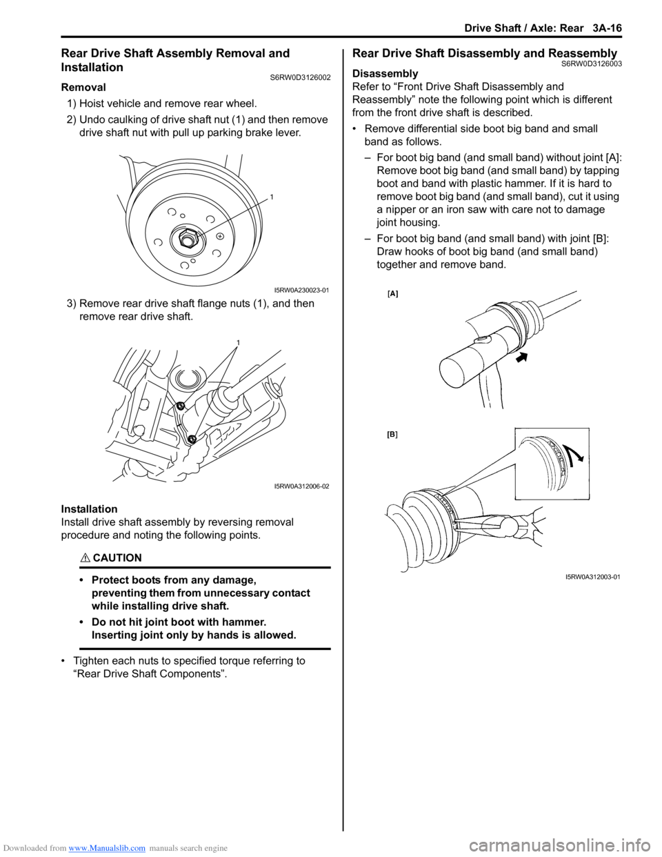
Removal
1) Hoist vehicle and remove rear wheel.
2) Undo caulking of drive shaft nut (1) and then remove
drive shaft nut with pull up parking brake lever.
3) Remove rear drive shaft flange nuts (1), and then
remove rear drive shaft.
Installation
Install drive shaft assembly by reversing removal
procedure and noting the following points.
CAUTION!
• Protect boots from any damage,
preventing them from unnecessary contact
while installing drive shaft.
• Do not hit joint boot with hammer.
Inserting joint only by hands is allowed.
• Tighten each nuts to specified torque referring to
“Rear Drive Shaft Components”.
Rear Drive Shaft Disassembly and ReassemblyS6RW0D3126003
Disassembly
Refer to “Front Drive Shaft Disassembly and
Reassembly” note the following point which is different
from the front drive shaft is described.
• Remove differential side boot big band and small
band as follows.
– For boot big band (and small band) without joint [A]:
Remove boot big band (and small band) by tapping
boot and band with plastic hammer. If it is hard to
remove boot big band (and small band), cut it using
a nipper or an iron saw with care not to damage
joint housing.
– For boot big band (and small band) with joint [B]:
Draw hooks of boot big band (and small band)
together and remove band.
1
I5RW0A230023-01
1
I5RW0A312006-02
I5RW0A312003-01
Page 496 of 1556
Downloaded from www.Manualslib.com manuals search engine 3A-17 Drive Shaft / Axle: Rear
Reassembly
Refer to “Front Drive Shaft Disassembly and
Reassembly” note the following points which is different
from the front drive shaft is described.
• Apply grease to each joint.
Grease color
Wheel side: Black
Differential side: Dark gray
Amount
Wheel side: 50 – 70 g (1.8 – 2.5 oz)
Differential side: 70 – 90 g (2.5 – 3.2 oz)
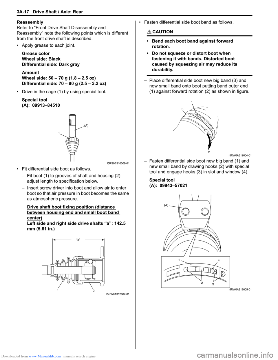
• Drive in the cage (1) by using special tool.
Special tool
(A): 09913–84510
• Fit differential side boot as follows.
– Fit boot (1) to grooves of shaft and housing (2)
adjust length to specification below.
– Insert screw driver into boot and allow air to enter
boot so that air pressure in boot becomes the same
as atmospheric pressure.
Drive shaft boot fixing position (distance
between housing end and small boot band
center)
Left side and right side drive shafts “a”: 142.5
mm (5.61 in.)• Fasten differential side boot band as follows.
CAUTION!
• Bend each boot band against forward
rotation.
• Do not squeeze or distort boot when
fastening it with bands. Distorted boot
caused by squeezing air may reduce its
durability.
– Place differential side boot new big band (3) and
new small band onto boot putting band outer end
(1) against forward rotation (2) as shown in figure.
– Fasten differential side boot new big band (1) and
new small band by drawing hooks (2) with special
tool and engage hooks (3) in slot and window (4).
Special tool
(A): 09943–57021
(A)
1
I5RS0B310009-01
“a”
2
1I5RW0A312007-01
I5RW0A312004-01
(A)
1
4
2
3
I5RW0A312005-01
Page 499 of 1556
Downloaded from www.Manualslib.com manuals search engine Differential: 3B-2
General Description
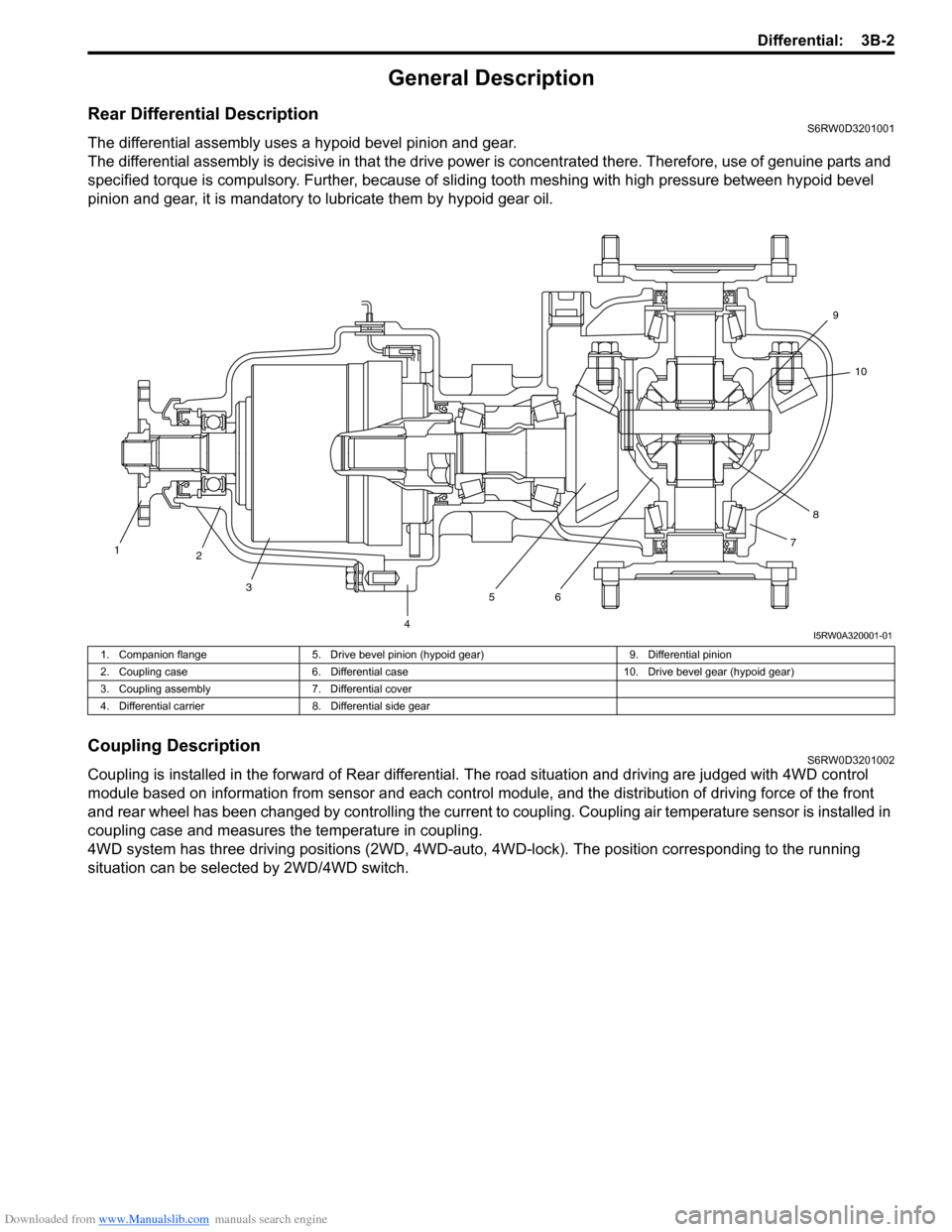
Rear Differential DescriptionS6RW0D3201001
The differential assembly uses a hypoid bevel pinion and gear.
The differential assembly is decisive in that the drive power is concentrated there. Therefore, use of genuine parts and
specified torque is compulsory. Further, because of sliding tooth meshing with high pressure between hypoid bevel
pinion and gear, it is mandatory to lubricate them by hypoid gear oil.
Coupling DescriptionS6RW0D3201002
Coupling is installed in the forward of Rear differential. The road situation and driving are judged with 4WD control
module based on information from sensor and each control module, and the distribution of driving force of the front
and rear wheel has been changed by controlling the current to coupling. Coupling air temperature sensor is installed in
coupling case and measures the temperature in coupling.
4WD system has three driving positions (2WD, 4WD-auto, 4WD-lock). The position corresponding to the running
situation can be selected by 2WD/4WD switch.
1
2
3
4567810 9
I5RW0A320001-01
1. Companion flange 5. Drive bevel pinion (hypoid gear) 9. Differential pinion
2. Coupling case 6. Differential case 10. Drive bevel gear (hypoid gear)
3. Coupling assembly 7. Differential cover
4. Differential carrier 8. Differential side gear
Page 501 of 1556
Downloaded from www.Manualslib.com manuals search engine Differential: 3B-4
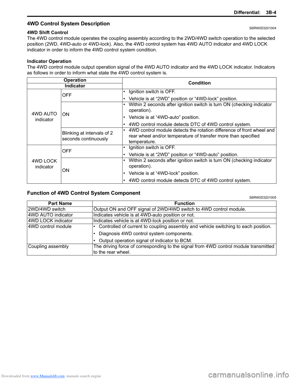
4WD Control System DescriptionS6RW0D3201004
4WD Shift Control
The 4WD control module operates the coupling assembly according to the 2WD/4WD switch operation to the selected
position (2WD, 4WD-auto or 4WD-lock). Also, the 4WD control system has 4WD AUTO indicator and 4WD LOCK
indicator in order to inform the 4WD control system condition.
Indicator Operation
The 4WD control module output operation signal of the 4WD AUTO indicator and the 4WD LOCK indicator. Indicators
as follows in order to inform what state the 4WD control system is.
Function of 4WD Control System ComponentS6RW0D3201005
Operation
Condition
Indicator
4WD AUTO
indicatorOFF• Ignition switch is OFF.
• Vehicle is at “2WD” position or “4WD-lock” position.
ON• Within 2 seconds after ignition switch is turn ON (checking indicator
operation).
• Vehicle is at “4WD-auto” position.
• 4WD control module detects DTC of 4WD control system.
Blinking at intervals of 2
seconds continuously• 4WD control module detects the rotation difference of front wheel and
rear wheel and/or temperature of transfer more than specified
temperature.
4WD LOCK
indicatorOFF• Ignition switch is OFF.
• Vehicle is at “2WD” position or “4WD-auto” position.
ON• Within 2 seconds after ignition switch is turn ON (checking indicator
operation).
• Vehicle is at “4WD-lock” position.
• 4WD control module detects DTC of 4WD control system.
Part Name Function
2WD/4WD switch Output ON and OFF signal of 2WD/4WD switch to 4WD control module.
4WD AUTO indicator Indicates vehicle is at 4WD-auto position or not.
4WD LOCK indicator Indicates vehicle is at 4WD-lock position or not.
4WD control module • Controlled of current to coupling assembly and vehicle switching to each position.
• Diagnosis 4WD control system components.
• Output operation signal of indicator to BCM.
Coupling assembly The driving force of corresponding to the signal from 4WD control module transmitted
to the rear wheel.
Page 510 of 1556

Downloaded from www.Manualslib.com manuals search engine 3B-13 Differential:
Scan Tool DataS6RW0D3204009
Scan Tool Data Definitions
Accel pedal Pos (Accelerator pedal position) (%)
Accelerator pedal opening ratio detected by signal on
CAN communication line fed from ECM.
Engine Speed (RPM)
This parameter indicates engine revolution calculated by
4WD control module.
4WD mode (2WD / AUTO / LOCK / ABS mode / Yaw
cont / ESP® req)
This parameter indicates 4WD mode according to 2WD/
4WD switch signal status detected by 4WD control
module.
4WD current (A)
This parameter indicates input current of coupling
assembly.
Battery voltage (V)
This parameter indicates battery voltage detected by
4WD control module.Coupling temp (°C, °F)
Coupling temperature detected by coupling air
temperature sensor installed in coupling assembly.
Wheel speed (F), Wheel speed (R) (km/h, mph)
Wheel speed is an ABS / ESP® control module internal
parameter. It is computed by reference pulses from the
wheel speed sensor.
F-R Wheel speed diff (Front-rear wheel speed
differential) (rpm)
This parameter indicates rotation difference between
front wheel and rear wheel detected by 4WD control
module.
4WD duty (%)
This parameter indicates operation rate of coupling
assembly. Scan tool data Vehicle conditionNormal condition / reference
values
�) Accel pedal PosIgnition switch ON after
warmed up engineAccelerator pedal released 0 – 5%
Accelerator pedal depressed
fully90 – 100%
�) Engine speed At engine idle speed Engine idle speed is display
�) 4WD mode2WD/4WD switch selected to 2WD position 2WD
2WD/4WD switch selected to AUTO position AUTO
2WD/4WD switch selected to LOCK position LOCK
ABS operating ABS mode
Ignition switch ON and engine stop Relay off
Stability control operating Yaw cont
ESP® operating ESP® mode
�) 4WD current Engine running 0 – 200 mA
�) Battery voltage At engine idle speed 10 – 14 V
�) Coupling temp Engine running –40 °C – 100 °C (–40 °F – 212 °F)
�) Wheel speed (F) Vehicle stop 0 km/h, 0 MPH
�) Wheel speed (R) Vehicle stop 0 km/h, 0 MPH
�) F-R Wheel speed
DiffVehicle stop 0 rpm
�) 4WD dutyIgnition switch ON and 2WD/4WD switch selected to
2WD position0%
Page 511 of 1556
Downloaded from www.Manualslib.com manuals search engine Differential: 3B-14
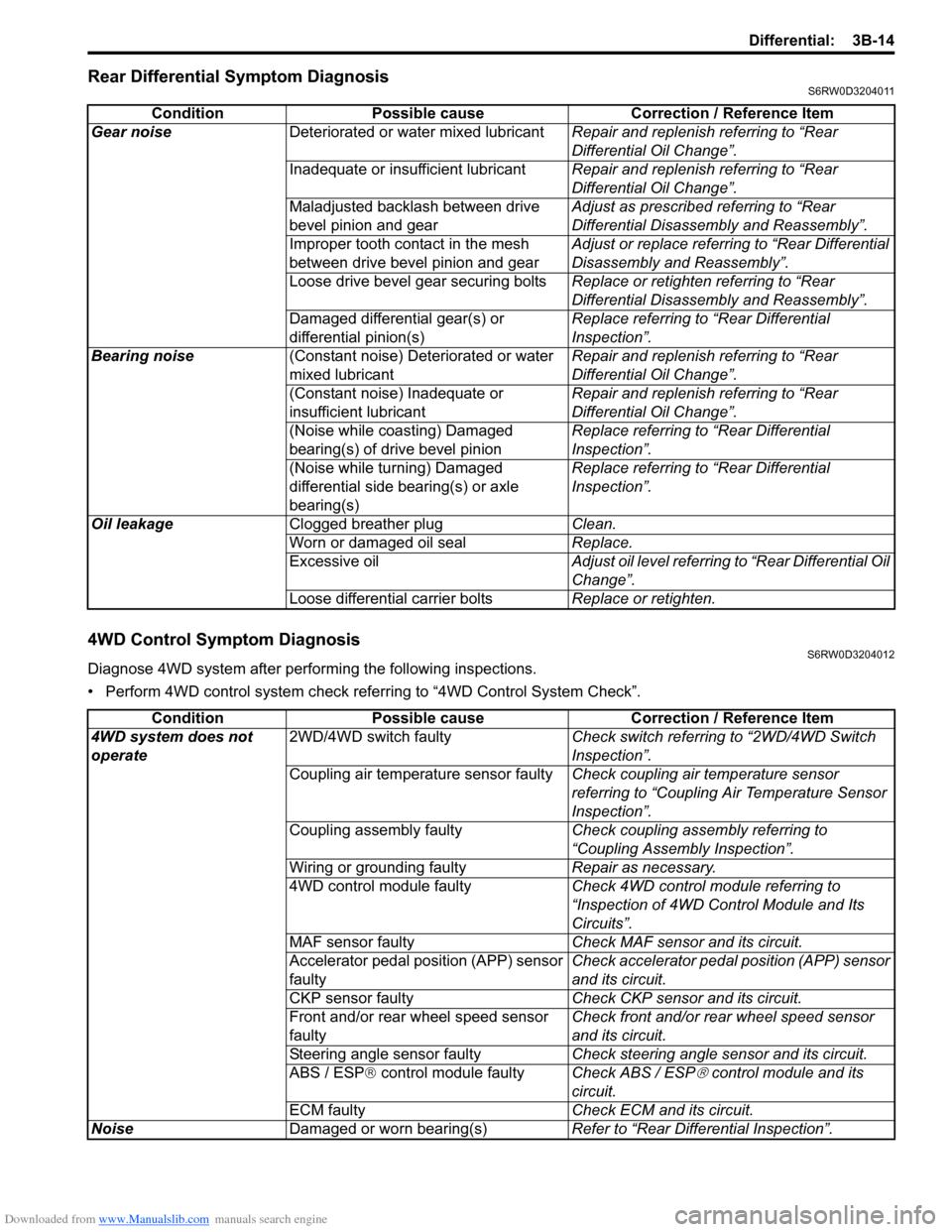
Rear Differential Symptom DiagnosisS6RW0D3204011
4WD Control Symptom DiagnosisS6RW0D3204012
Diagnose 4WD system after performing the following inspections.
• Perform 4WD control system check referring to “4WD Control System Check”. Condition Possible cause Correction / Reference Item
Gear noiseDeteriorated or water mixed lubricantRepair and replenish referring to “Rear
Differential Oil Change”.
Inadequate or insufficient lubricantRepair and replenish referring to “Rear
Differential Oil Change”.
Maladjusted backlash between drive
bevel pinion and gearAdjust as prescribed referring to “Rear
Differential Disassembly and Reassembly”.
Improper tooth contact in the mesh
between drive bevel pinion and gearAdjust or replace referring to “Rear Differential
Disassembly and Reassembly”.
Loose drive bevel gear securing boltsReplace or retighten referring to “Rear
Differential Disassembly and Reassembly”.
Damaged differential gear(s) or
differential pinion(s)Replace referring to “Rear Differential
Inspection”.
Bearing noise(Constant noise) Deteriorated or water
mixed lubricantRepair and replenish referring to “Rear
Differential Oil Change”.
(Constant noise) Inadequate or
insufficient lubricantRepair and replenish referring to “Rear
Differential Oil Change”.
(Noise while coasting) Damaged
bearing(s) of drive bevel pinionReplace referring to “Rear Differential
Inspection”.
(Noise while turning) Damaged
differential side bearing(s) or axle
bearing(s)Replace referring to “Rear Differential
Inspection”.
Oil leakageClogged breather plugClean.
Worn or damaged oil sealReplace.
Excessive oilAdjust oil level referring to “Rear Differential Oil
Change”.
Loose differential carrier boltsReplace or retighten.
Condition Possible cause Correction / Reference Item
4WD system does not
operate2WD/4WD switch faultyCheck switch referring to “2WD/4WD Switch
Inspection”.
Coupling air temperature sensor faultyCheck coupling air temperature sensor
referring to “Coupling Air Temperature Sensor
Inspection”.
Coupling assembly faultyCheck coupling assembly referring to
“Coupling Assembly Inspection”.
Wiring or grounding faultyRepair as necessary.
4WD control module faultyCheck 4WD control module referring to
“Inspection of 4WD Control Module and Its
Circuits”.
MAF sensor faultyCheck MAF sensor and its circuit.
Accelerator pedal position (APP) sensor
faultyCheck accelerator pedal position (APP) sensor
and its circuit.
CKP sensor faultyCheck CKP sensor and its circuit.
Front and/or rear wheel speed sensor
faultyCheck front and/or rear wheel speed sensor
and its circuit.
Steering angle sensor faultyCheck steering angle sensor and its circuit.
ABS / ESP® control module faultyCheck ABS / ESP
® control module and its
circuit.
ECM faultyCheck ECM and its circuit.
NoiseDamaged or worn bearing(s)Refer to “Rear Differential Inspection”.
Page 531 of 1556
Downloaded from www.Manualslib.com manuals search engine Differential: 3B-34
Front Mounting Arm and/or Rear Mounting
Bracket Assembly Removal and Installation
S6RW0D3206010
Remove and install front mounting arm and/or rear
mounting bracket after rear differential removed.
For tightening torque of each bolt and nut, refer to “Rear
Differential Mountings Components”.
Rear Mounting Bracket Assembly Disassembly
and Reassembly
S6RW0D3206011
Disassembly
Drive out mountings from rear mounting bracket using
special tool and hydraulic press.
Special tool
(A): 09913–70123
(B): 09951–26020
Reassembly
Press mountings in rear mounting bracket using special
tool and hydraulic press with caring its installation
position shown in figure.
Special tool
(A): 09913–85210
(B): 09951–26020
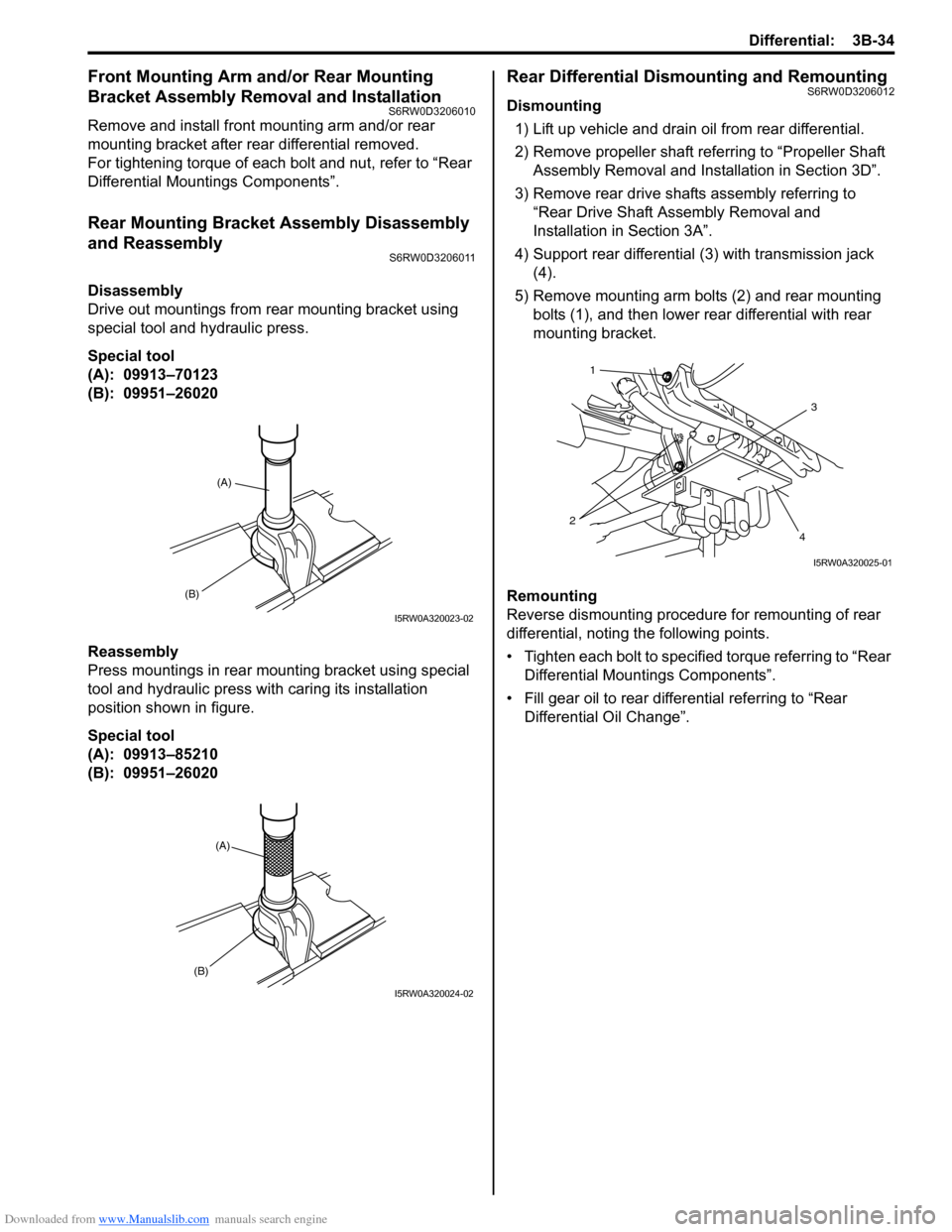
Rear Differential Dismounting and RemountingS6RW0D3206012
Dismounting
1) Lift up vehicle and drain oil from rear differential.
2) Remove propeller shaft referring to “Propeller Shaft
Assembly Removal and Installation in Section 3D”.
3) Remove rear drive shafts assembly referring to
“Rear Drive Shaft Assembly Removal and
Installation in Section 3A”.
4) Support rear differential (3) with transmission jack
(4).
5) Remove mounting arm bolts (2) and rear mounting
bolts (1), and then lower rear differential with rear
mounting bracket.
Remounting
Reverse dismounting procedure for remounting of rear
differential, noting the following points.
• Tighten each bolt to specified torque referring to “Rear
Differential Mountings Components”.
• Fill gear oil to rear differential referring to “Rear
Differential Oil Change”.
(B)
(A)
I5RW0A320023-02
(A)
(B)
I5RW0A320024-02
3
4 21
I5RW0A320025-01
Page 532 of 1556
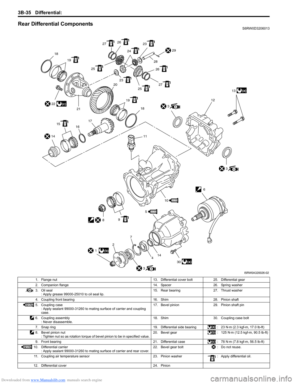
Downloaded from www.Manualslib.com manuals search engine 3B-35 Differential:
Rear Differential ComponentsS6RW0D3206013
4 5
9
2
30
6
(a)13
12
(a)
3
A
3A
141617 2118
29
3A
1(b)
22
1217G
101217G
11
8OIL
15OIL
19 20OIL
23OIL
25OIL27OIL
27OIL
25OIL
19OIL18
26 28
OIL
26OIL23OIL
24OIL
(c)
14
7
I5RW0A320026-02
1. Flange nut 13. Differential cover bolt 25. Differential gear
2. Companion flange 14. Spacer 26. Spring washer
3. Oil seal
: Apply grease 99000-25010 to oil seal lip.15. Rear bearing 27. Thrust washer
4. Coupling front bearing 16. Shim 28. Pinion shaft
5. Coupling case
: Apply sealant 99000-31260 to mating surface of carrier and coupling
case.17. Bevel pinion 29. Pinion shaft pin
6. Coupling assembly
: Never disassemble.18. Shim 30. Coupling case bolt
7. Snap ring 19. Differential side bearing : 23 N⋅m (2.3 kgf-m, 17.0 lb-ft)
8. Bevel pinion nut
: Tighten nut so as rotation torque of bevel pinion to be in specified value.20. Bevel gear : 125 N⋅m (12.5 kgf-m, 90.5 lb-ft)
9. Front bearing 21. Differential case : 78 N⋅m (7.8 kgf-m, 56.5 lb-ft)
10. Differential carrier
: Apply sealant 99000-31260 to mating surface of carrier and rear cover.22. Bevel gear bolt : Do not reuse.
11. Coupling air temperature sensor 23. Pinion washer : Apply differential oil.
12. Differential cover 24. Pinion