sensor SUZUKI SX4 2006 1.G Service Workshop Manual
[x] Cancel search | Manufacturer: SUZUKI, Model Year: 2006, Model line: SX4, Model: SUZUKI SX4 2006 1.GPages: 1556, PDF Size: 37.31 MB
Page 947 of 1556
Downloaded from www.Manualslib.com manuals search engine Air Conditioning System: Manual Type 7B-7
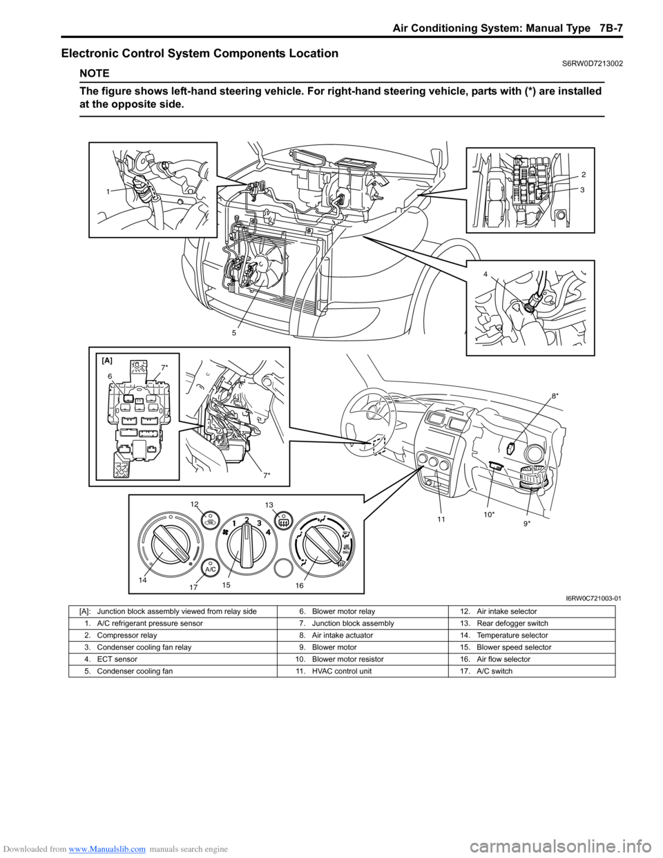
Electronic Control System Components LocationS6RW0D7213002
NOTE
The figure shows left-hand steering vehicle. For right-hand steering vehicle, parts with (*) are installed
at the opposite side.
[A]
8*
9* 10*
11
1
5
7*
6
7*
12
13
14
1715
1642
3
I6RW0C721003-01
[A]: Junction block assembly viewed from relay side 6. Blower motor relay 12. Air intake selector
1. A/C refrigerant pressure sensor 7. Junction block assembly 13. Rear defogger switch
2. Compressor relay 8. Air intake actuator 14. Temperature selector
3. Condenser cooling fan relay 9. Blower motor 15. Blower speed selector
4. ECT sensor 10. Blower motor resistor 16. Air flow selector
5. Condenser cooling fan 11. HVAC control unit 17. A/C switch
Page 953 of 1556
Downloaded from www.Manualslib.com manuals search engine Air Conditioning System: Manual Type 7B-13
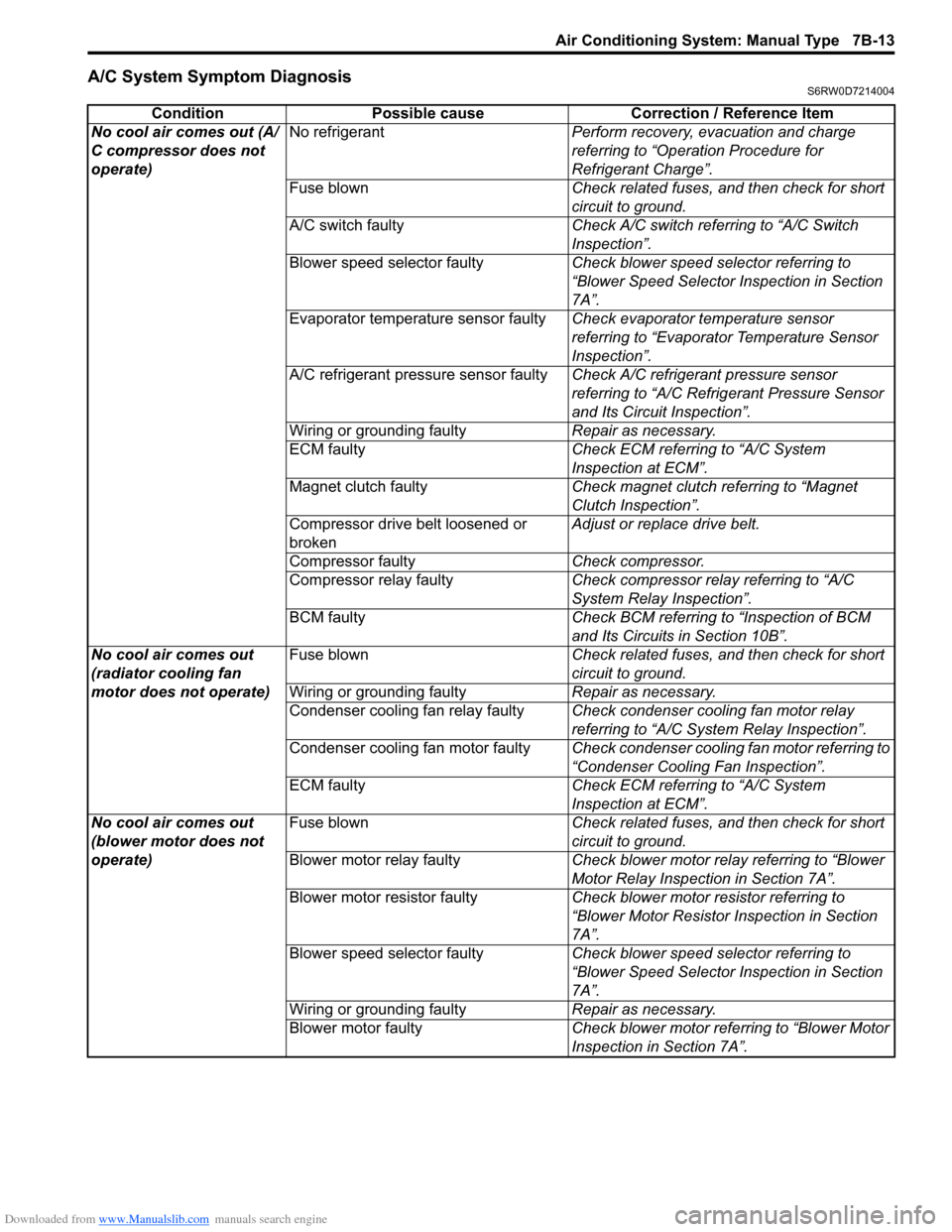
A/C System Symptom DiagnosisS6RW0D7214004
Condition Possible cause Correction / Reference Item
No cool air comes out (A/
C compressor does not
operate)No refrigerantPerform recovery, evacuation and charge
referring to “Operation Procedure for
Refrigerant Charge”.
Fuse blownCheck related fuses, and then check for short
circuit to ground.
A/C switch faultyCheck A/C switch referring to “A/C Switch
Inspection”.
Blower speed selector faultyCheck blower speed selector referring to
“Blower Speed Selector Inspection in Section
7A”.
Evaporator temperature sensor faultyCheck evaporator temperature sensor
referring to “Evaporator Temperature Sensor
Inspection”.
A/C refrigerant pressure sensor faultyCheck A/C refrigerant pressure sensor
referring to “A/C Refrigerant Pressure Sensor
and Its Circuit Inspection”.
Wiring or grounding faultyRepair as necessary.
ECM faultyCheck ECM referring to “A/C System
Inspection at ECM”.
Magnet clutch faultyCheck magnet clutch referring to “Magnet
Clutch Inspection”.
Compressor drive belt loosened or
brokenAdjust or replace drive belt.
Compressor faultyCheck compressor.
Compressor relay faultyCheck compressor relay referring to “A/C
System Relay Inspection”.
BCM faultyCheck BCM referring to “Inspection of BCM
and Its Circuits in Section 10B”.
No cool air comes out
(radiator cooling fan
motor does not operate)Fuse blownCheck related fuses, and then check for short
circuit to ground.
Wiring or grounding faultyRepair as necessary.
Condenser cooling fan relay faultyCheck condenser cooling fan motor relay
referring to “A/C System Relay Inspection”.
Condenser cooling fan motor faultyCheck condenser cooling fan motor referring to
“Condenser Cooling Fan Inspection”.
ECM faultyCheck ECM referring to “A/C System
Inspection at ECM”.
No cool air comes out
(blower motor does not
operate)Fuse blownCheck related fuses, and then check for short
circuit to ground.
Blower motor relay faultyCheck blower motor relay referring to “Blower
Motor Relay Inspection in Section 7A”.
Blower motor resistor faultyCheck blower motor resistor referring to
“Blower Motor Resistor Inspection in Section
7A”.
Blower speed selector faultyCheck blower speed selector referring to
“Blower Speed Selector Inspection in Section
7A”.
Wiring or grounding faultyRepair as necessary.
Blower motor faultyCheck blower motor referring to “Blower Motor
Inspection in Section 7A”.
Page 954 of 1556
Downloaded from www.Manualslib.com manuals search engine 7B-14 Air Conditioning System: Manual Type
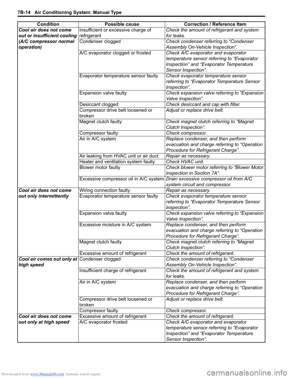
Cool air does not come
out or insufficient cooling
(A/C compressor normal
operation)Insufficient or excessive charge of
refrigerantCheck the amount of refrigerant and system
for leaks.
Condenser cloggedCheck condenser referring to “Condenser
Assembly On-Vehicle Inspection”.
A/C evaporator clogged or frostedCheck A/C evaporator and evaporator
temperature sensor referring to “Evaporator
Inspection” and “Evaporator Temperature
Sensor Inspection”.
Evaporator temperature sensor faultyCheck evaporator temperature sensor
referring to “Evaporator Temperature Sensor
Inspection”.
Expansion valve faultyCheck expansion valve referring to “Expansion
Valve Inspection”.
Desiccant cloggedCheck desiccant and cap with filter.
Compressor drive belt loosened or
brokenAdjust or replace drive belt.
Magnet clutch faultyCheck magnet clutch referring to “Magnet
Clutch Inspection”.
Compressor faultyCheck compressor.
Air in A/C systemReplace condenser, and then perform
evacuation and charge referring to “Operation
Procedure for Refrigerant Charge”.
Air leaking from HVAC unit or air ductRepair as necessary.
Heater and ventilation system faultyCheck HVAC unit.
Blower motor faultyCheck blower motor referring to “Blower Motor
Inspection in Section 7A”.
Excessive compressor oil in A/C systemDrain excessive compressor oil from A/C
system circuit and compressor.
Cool air does not come
out only intermittentlyWiring connection faultyRepair as necessary.
Evaporator temperature sensor faultyCheck evaporator temperature sensor
referring to “Evaporator Temperature Sensor
Inspection”.
Expansion valve faultyCheck expansion valve referring to “Expansion
Valve Inspection”.
Excessive moisture in A/C systemReplace condenser, and then perform
evacuation and charge referring to “Operation
Procedure for Refrigerant Charge”.
Magnet clutch faultyCheck magnet clutch referring to “Magnet
Clutch Inspection”.
Excessive amount of refrigerantCheck the amount of refrigerant.
Cool air comes out only at
high speedCondenser cloggedCheck condenser referring to “Condenser
Assembly On-Vehicle Inspection”.
Insufficient charge of refrigerantCheck the amount of refrigerant and system
for leaks.
Air in A/C systemReplace condenser, and then perform
evacuation and charge referring to “Operation
Procedure for Refrigerant Charge”.
Compressor drive belt loosened or
brokenAdjust or replace drive belt.
Compressor faultyCheck compressor.
Cool air does not come
out only at high speedExcessive amount of refrigerantCheck the amount of refrigerant.
A/C evaporator frostedCheck A/C evaporator and evaporator
temperature sensor referring to “Evaporator
Inspection” and “Evaporator Temperature
Sensor Inspection”. Condition Possible cause Correction / Reference Item
Page 955 of 1556
Downloaded from www.Manualslib.com manuals search engine Air Conditioning System: Manual Type 7B-15
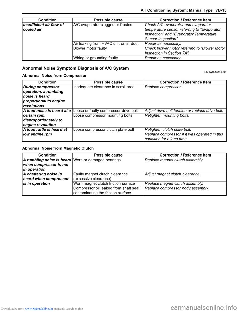
Abnormal Noise Symptom Diagnosis of A/C SystemS6RW0D7214005
Abnormal Noise from Compressor
Abnormal Noise from Magnetic ClutchInsufficient air flow of
cooled airA/C evaporator clogged or frostedCheck A/C evaporator and evaporator
temperature sensor referring to “Evaporator
Inspection” and “Evaporator Temperature
Sensor Inspection”.
Air leaking from HVAC unit or air ductRepair as necessary.
Blower motor faultyCheck blower motor referring to “Blower Motor
Inspection in Section 7A”.
Wiring or grounding faultyRepair as necessary. Condition Possible cause Correction / Reference Item
Condition Possible cause Correction / Reference Item
During compressor
operation, a rumbling
noise is heard
proportional to engine
revolutionsInadequate clearance in scroll areaReplace compressor.
A loud noise is heard at a
certain rpm,
disproportionately to
engine revolutionLoose or faulty compressor drive beltAdjust drive belt tension or replace drive belt.
Loose compressor mounting boltsRetighten mounting bolts.
A loud rattle is heard at
low engine rpmLoose compressor clutch plate boltRetighten clutch plate bolt.
Replace compressor if it was operated in this
condition for a long time.
Condition Possible cause Correction / Reference Item
A rumbling noise is heard
when compressor is not
in operationWorn or damaged bearingsReplace magnet clutch assembly.
A chattering noise is
heard when compressor
is in operationFaulty magnet clutch clearance
(excessive clearance)Adjust magnet clutch clearance.
Worn magnet clutch friction surfaceReplace magnet clutch assembly.
Compressor oil leaked from shaft seal,
contaminating the friction surfaceReplace compressor body assembly.
Page 965 of 1556
Downloaded from www.Manualslib.com manuals search engine Air Conditioning System: Manual Type 7B-25
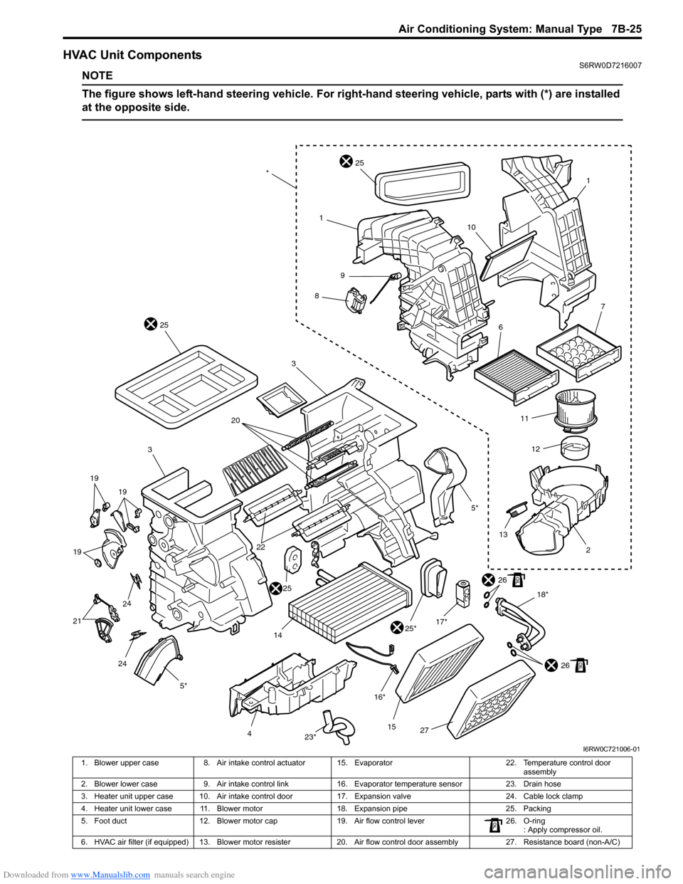
HVAC Unit ComponentsS6RW0D7216007
NOTE
The figure shows left-hand steering vehicle. For right-hand steering vehicle, parts with (*) are installed
at the opposite side.
1
10
1
9
8
25
25
3
20
3
19 19
19
24
24 21
4
23*27 15 16* 14
25*18*2
2526
17*1312 11
5*22
67
*
26
5*
I6RW0C721006-01
1. Blower upper case 8. Air intake control actuator 15. Evaporator 22. Temperature control door
assembly
2. Blower lower case 9. Air intake control link 16. Evaporator temperature sensor 23. Drain hose
3. Heater unit upper case 10. Air intake control door 17. Expansion valve 24. Cable lock clamp
4. Heater unit lower case 11. Blower motor 18. Expansion pipe 25. Packing
5. Foot duct 12. Blower motor cap 19. Air flow control lever 26. O-ring
: Apply compressor oil.
6. HVAC air filter (if equipped) 13. Blower motor resister 20. Air flow control door assembly 27. Resistance board (non-A/C)
Page 967 of 1556
Downloaded from www.Manualslib.com manuals search engine Air Conditioning System: Manual Type 7B-27
Installation
Reverse removal procedure noting the following
instructions.
• Replenish specified amount of compressor oil to
compressor suction side referring to “Replenishing
Compressor Oil” in “Operation Procedure for
Refrigerant Charge”.
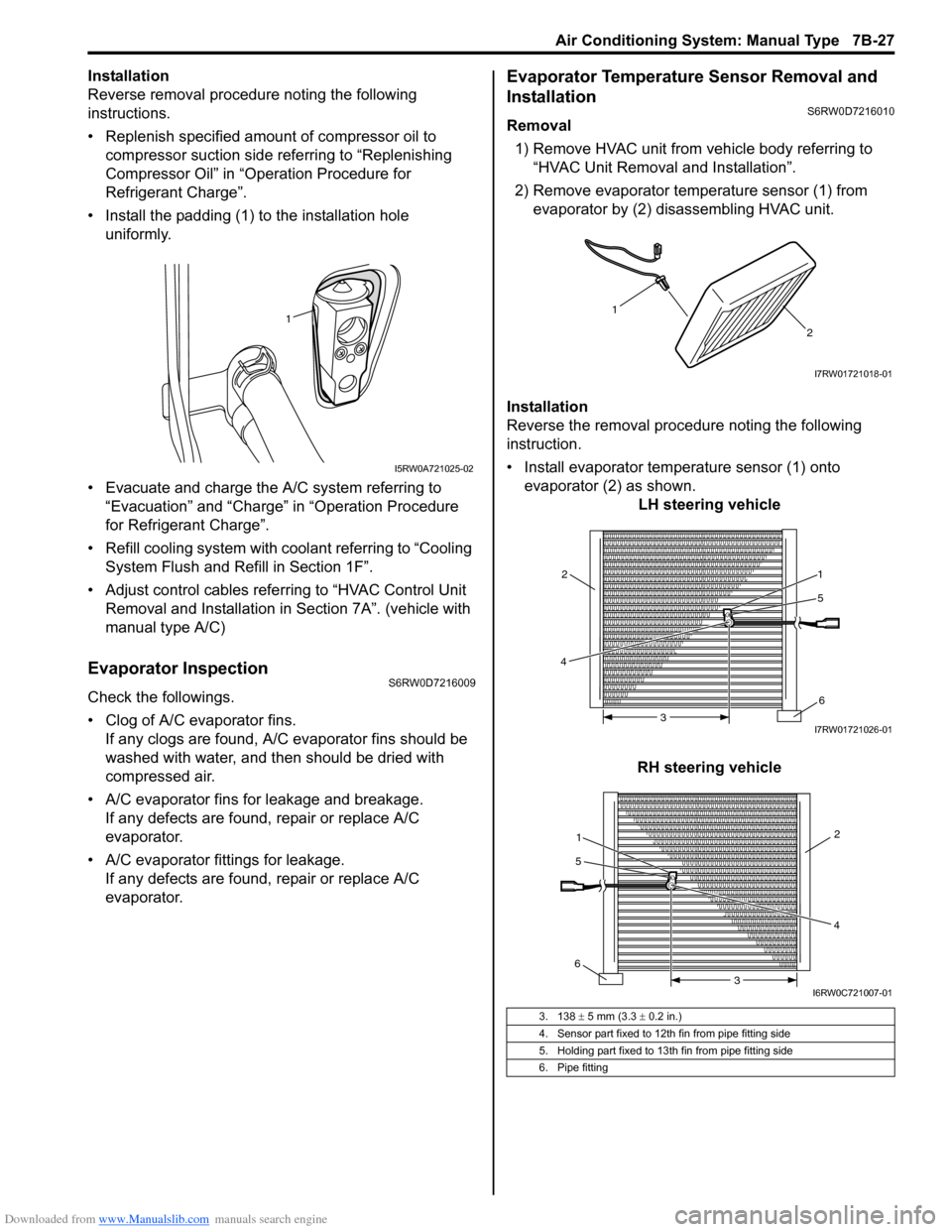
• Install the padding (1) to the installation hole
uniformly.
• Evacuate and charge the A/C system referring to
“Evacuation” and “Charge” in “Operation Procedure
for Refrigerant Charge”.
• Refill cooling system with coolant referring to “Cooling
System Flush and Refill in Section 1F”.
• Adjust control cables referring to “HVAC Control Unit
Removal and Installation in Section 7A”. (vehicle with
manual type A/C)
Evaporator InspectionS6RW0D7216009
Check the followings.
• Clog of A/C evaporator fins.
If any clogs are found, A/C evaporator fins should be
washed with water, and then should be dried with
compressed air.
• A/C evaporator fins for leakage and breakage.
If any defects are found, repair or replace A/C
evaporator.
• A/C evaporator fittings for leakage.
If any defects are found, repair or replace A/C
evaporator.
Evaporator Temperature Sensor Removal and
Installation
S6RW0D7216010
Removal
1) Remove HVAC unit from vehicle body referring to
“HVAC Unit Removal and Installation”.
2) Remove evaporator temperature sensor (1) from
evaporator by (2) disassembling HVAC unit.
Installation
Reverse the removal procedure noting the following
instruction.
• Install evaporator temperature sensor (1) onto
evaporator (2) as shown.
LH steering vehicle
RH steering vehicle
1
I5RW0A721025-02
3. 138 ± 5 mm (3.3 ± 0.2 in.)
4. Sensor part fixed to 12th fin from pipe fitting side
5. Holding part fixed to 13th fin from pipe fitting side
6. Pipe fitting
1
2
I7RW01721018-01
5
4
6 1
2
3I7RW01721026-01
1
5
642
3
I6RW0C721007-01
Page 968 of 1556

Downloaded from www.Manualslib.com manuals search engine 7B-28 Air Conditioning System: Manual Type
Evaporator Temperature Sensor InspectionS6RW0D7216011
Check resistance between terminals of evaporator
temperature sensor (1).
If check results are as not specified, replace evaporator
temperature sensor.
Evaporator temperature sensor resistance
0 °C (32 °F): 6.6 – 6.8 kΩ
25 °C (77 °F): 2.0 – 2.1 kΩ
Expansion Valve Removal and InstallationS6RW0D7216012
Removal
1) Recover refrigerant from the A/C system with
recovery and recycling equipment referring to
“Recovery” in “Operation Procedure for Refrigerant
Charge”.
2) Loosen a bolt (1) and remove pipes from expansion
valve (2).
3) Loosen bolts (3) and remove expansion valve.
Installation
Reverse removal procedure noting the following
instructions.
• Apply compressor oil to O-ring of expansion valve and
pipes.
• Tighten expansion valve bolts to specified torque.
Tightening torque
Expansion valve bolt: 4.5 N·m (0.45 kgf-m, 3.5 lb-
ft)
• Evacuate and charge the A/C system referring to
“Evacuation” and “Charge” in “Operation Procedure
for Refrigerant Charge”.
Expansion Valve InspectionS6RW0D7216013
Refer to “A/C System Performance Inspection”.
[A]: Resistance
[B]: Temperature
(kΩ)
6.75
2.00
0
3225
77 [A]
[B]
(˚C)
(˚F)
1
I7RW01721020-01
1
22 3
I4RS0A720028-01
Page 969 of 1556

Downloaded from www.Manualslib.com manuals search engine Air Conditioning System: Manual Type 7B-29
A/C Refrigerant Pressure Sensor and Its Circuit
Inspection
S6RW0D7216014
1) Disconnect A/C refrigerant pressure sensor
connector.
2) Turn ignition switch to ON position.
3) Check if voltage between “RED” wire terminal and
“ORN” wire terminal of A/C refrigerant pressure
sensor connector is 4.75 V to 5.25 V.
If not, check A/C refrigerant pressure sensor circuit.
4) Connect A/C refrigerant pressure sensor connector
with ignition switch turned OFF.
5) Connect manifold gauge set to the charging valves.
6) Check A/C refrigerant pressure sensor voltage of
ECM connector referring to “A/C System Inspection
at ECM”.
If voltage is not as specified below, replace A/C
refrigerant pressure sensor.
A/C refrigerant pressure sensor voltage
specifications (A/C refrigerant pressure measured
by manifold gauge)
0.8 MPa (8.0 kgf/cm2, 116 psi): 1.40 – 1.78 V
1.4 MPa (14 kgf/cm2, 203 psi): 2.18 – 2.64 V
1.6 MPa (16 kgf/cm2, 232 psi): 2.44 – 2.92 V
1.8 MPa (18 kgf/cm2, 261 psi): 2.70 – 3.21 V
A/C Refrigerant Pressure Sensor Removal and
Installation
S6RW0D7216015
Removal
1) Recover refrigerant from the A/C system with the
recovery and recycling equipment referring to
“Recovery” in “Operation Procedure for Refrigerant
Charge”.
2) Disconnect negative (–) cable from battery.
3) Disconnect A/C refrigerant pressure sensor
connector.
4) Remove A/C refrigerant pressure sensor (1) from
liquid pipe (2).Installation
Reverse removal procedure noting the following
instructions.
• Apply compressor oil to O-ring of A/C refrigerant
pressure sensor.
• Tighten A/C refrigerant pressure sensor to specified
torque.
Tightening torque
A/C refrigerant pressure sensor (a): 11 N·m (1.1
kgf-m, 8.0 lb-ft)
• Evacuate and charge the A/C system referring to
“Evacuation” and “Charge” in “Operation Procedure
for Refrigerant Charge”.
A/C Switch InspectionS6RW0D7216016
• Check that there is continuity between terminal (1)
and terminal (2) when A/C switch is at ON position.
• Check that there is no continuity between terminal (1)
and terminal (2) when A/C switch is at OFF position.
If check result does not meet the above conditions,
replace HVAC control unit.
2
1
I5RW0A721029-01
(a)
I5RW0A721030-01
1
2
I5RW0A721031-01
Page 977 of 1556
Downloaded from www.Manualslib.com manuals search engine Air Conditioning System: Manual Type 7B-37
Specifications
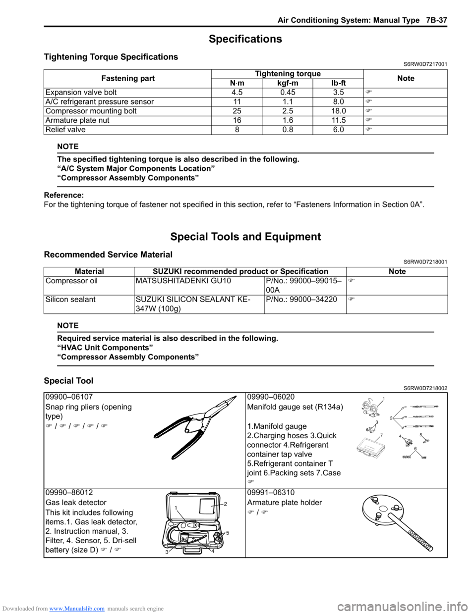
Tightening Torque SpecificationsS6RW0D7217001
NOTE
The specified tightening torque is also described in the following.
“A/C System Major Components Location”
“Compressor Assembly Components”
Reference:
For the tightening torque of fastener not specified in this section, refer to “Fasteners Information in Section 0A”.
Special Tools and Equipment
Recommended Service MaterialS6RW0D7218001
NOTE
Required service material is also described in the following.
“HVAC Unit Components”
“Compressor Assembly Components”
Special ToolS6RW0D7218002
Fastening partTightening torque
Note
N⋅mkgf-mlb-ft
Expansion valve bolt 4.5 0.45 3.5�)
A/C refrigerant pressure sensor 11 1.1 8.0�)
Compressor mounting bolt 25 2.5 18.0�)
Armature plate nut 16 1.6 11.5�)
Relief valve 8 0.8 6.0�)
Material SUZUKI recommended product or Specification Note
Compressor oil MATSUSHITADENKI GU10 P/No.: 99000–99015–
00A�)
Silicon sealant SUZUKI SILICON SEALANT KE-
347W (100g)P/No.: 99000–34220�)
09900–06107 09990–06020
Snap ring pliers (opening
type)Manifold gauge set (R134a)
�) / �) / �) / �) / �)1.Manifold gauge
2.Charging hoses 3.Quick
connector 4.Refrigerant
container tap valve
5.Refrigerant container T
joint 6.Packing sets 7.Case
�)
09990–86012 09991–06310
Gas leak detector Armature plate holder
This kit includes following
items.1. Gas leak detector,
2. Instruction manual, 3.
Filter, 4. Sensor, 5. Dri-sell
battery (size D) �) / �)�) / �)
12
34
5
Page 979 of 1556
Downloaded from www.Manualslib.com manuals search engine Air Conditioning System: Automatic Type 7B-39
General Description
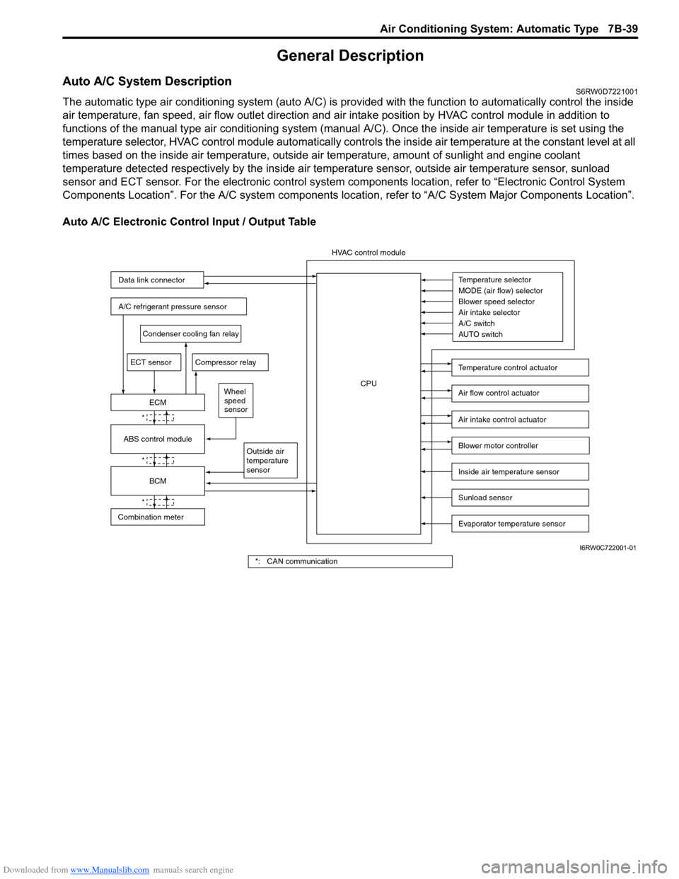
Auto A/C System DescriptionS6RW0D7221001
The automatic type air conditioning system (auto A/C) is provided with the function to automatically control the inside
air temperature, fan speed, air flow outlet direction and air intake position by HVAC control module in addition to
functions of the manual type air conditioning system (manual A/C). Once the inside air temperature is set using the
temperature selector, HVAC control module automatically controls the inside air temperature at the constant level at all
times based on the inside air temperature, outside air temperature, amount of sunlight and engine coolant
temperature detected respectively by the inside air temperature sensor, outside air temperature sensor, sunload
sensor and ECT sensor. For the electronic control system components location, refer to “Electronic Control System
Components Location”. For the A/C system components location, refer to “A/C System Major Components Location”.
Auto A/C Electronic Control Input / Output Table
Temperature selector
MODE (air flow) selector
Blower speed selector
Air intake selector
AUTO switch A/C switch
Outside air
temperature
sensor
A/C refrigerant pressure sensor
Compressor relay
Blower motor controller
Temperature control actuator
Air flow control actuator
Air intake control actuator
BCM
ECM
Data link connector
HVAC control module
CPU
ECT sensor
Sunload sensor
Inside air temperature sensor
Evaporator temperature sensor
Condenser cooling fan relay
Wheel
speed
sensor
*
*
*
Combination meterABS control module
I6RW0C722001-01
*: CAN communication