Output speed sensor SUZUKI SX4 2006 1.G Service Owner's Guide
[x] Cancel search | Manufacturer: SUZUKI, Model Year: 2006, Model line: SX4, Model: SUZUKI SX4 2006 1.GPages: 1556, PDF Size: 37.31 MB
Page 646 of 1556
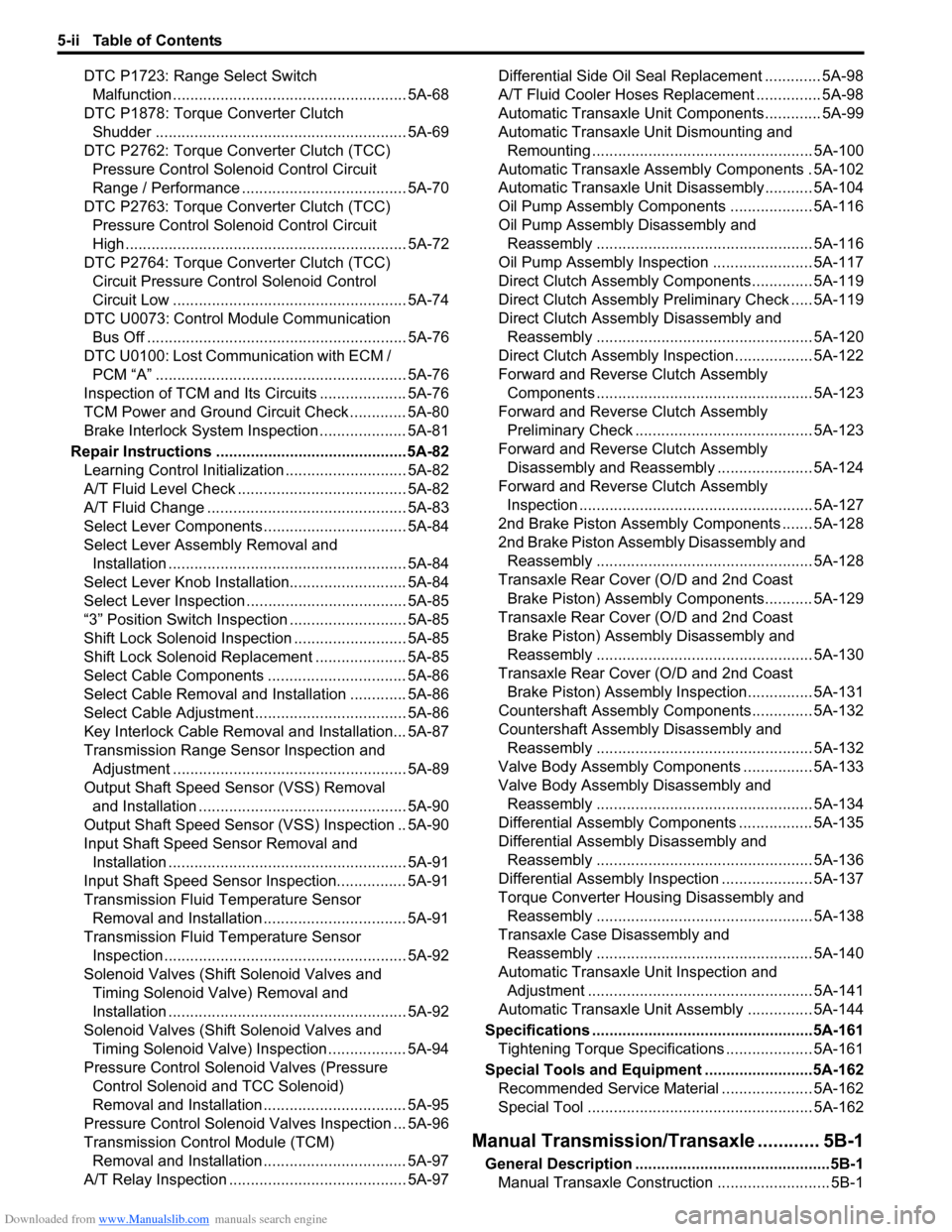
Downloaded from www.Manualslib.com manuals search engine 5-ii Table of Contents
DTC P1723: Range Select Switch
Malfunction ...................................................... 5A-68
DTC P1878: Torque Converter Clutch
Shudder .......................................................... 5A-69
DTC P2762: Torque Converter Clutch (TCC)
Pressure Control Solenoid Control Circuit
Range / Performance ...................................... 5A-70
DTC P2763: Torque Converter Clutch (TCC)
Pressure Control Solenoid Control Circuit
High ................................................................. 5A-72
DTC P2764: Torque Converter Clutch (TCC)
Circuit Pressure Control Solenoid Control
Circuit Low ...................................................... 5A-74
DTC U0073: Control Module Communication
Bus Off ............................................................ 5A-76
DTC U0100: Lost Communication with ECM /
PCM “A” .......................................................... 5A-76
Inspection of TCM and Its Circuits .................... 5A-76
TCM Power and Ground Circuit Check ............. 5A-80
Brake Interlock System Inspection .................... 5A-81
Repair Instructions ............................................5A-82
Learning Control Initialization ............................ 5A-82
A/T Fluid Level Check ....................................... 5A-82
A/T Fluid Change .............................................. 5A-83
Select Lever Components ................................. 5A-84
Select Lever Assembly Removal and
Installation ....................................................... 5A-84
Select Lever Knob Installation........................... 5A-84
Select Lever Inspection ..................................... 5A-85
“3” Position Switch Inspection ........................... 5A-85
Shift Lock Solenoid Inspection .......................... 5A-85
Shift Lock Solenoid Replacement ..................... 5A-85
Select Cable Components ................................ 5A-86
Select Cable Removal and Installation ............. 5A-86
Select Cable Adjustment ................................... 5A-86
Key Interlock Cable Removal and Installation... 5A-87
Transmission Range Sensor Inspection and
Adjustment ...................................................... 5A-89
Output Shaft Speed Sensor (VSS) Removal
and Installation ................................................ 5A-90
Output Shaft Speed Sensor (VSS) Inspection .. 5A-90
Input Shaft Speed Sensor Removal and
Installation ....................................................... 5A-91
Input Shaft Speed Sensor Inspection................ 5A-91
Transmission Fluid Temperature Sensor
Removal and Installation ................................. 5A-91
Transmission Fluid Temperature Sensor
Inspection ........................................................ 5A-92
Solenoid Valves (Shift Solenoid Valves and
Timing Solenoid Valve) Removal and
Installation ....................................................... 5A-92
Solenoid Valves (Shift Solenoid Valves and
Timing Solenoid Valve) Inspection .................. 5A-94
Pressure Control Solenoid Valves (Pressure
Control Solenoid and TCC Solenoid)
Removal and Installation ................................. 5A-95
Pressure Control Solenoid Valves Inspection ... 5A-96
Transmission Control Module (TCM)
Removal and Installation ................................. 5A-97
A/T Relay Inspection ......................................... 5A-97Differential Side Oil Seal Replacement ............. 5A-98
A/T Fluid Cooler Hoses Replacement ............... 5A-98
Automatic Transaxle Unit Components............. 5A-99
Automatic Transaxle Unit Dismounting and
Remounting ................................................... 5A-100
Automatic Transaxle Assembly Components . 5A-102
Automatic Transaxle Unit Disassembly........... 5A-104
Oil Pump Assembly Components ................... 5A-116
Oil Pump Assembly Disassembly and
Reassembly .................................................. 5A-116
Oil Pump Assembly Inspection ....................... 5A-117
Direct Clutch Assembly Components.............. 5A-119
Direct Clutch Assembly Preliminary Check ..... 5A-119
Direct Clutch Assembly Disassembly and
Reassembly .................................................. 5A-120
Direct Clutch Assembly Inspection.................. 5A-122
Forward and Reverse Clutch Assembly
Components .................................................. 5A-123
Forward and Reverse Clutch Assembly
Preliminary Check ......................................... 5A-123
Forward and Reverse Clutch Assembly
Disassembly and Reassembly ...................... 5A-124
Forward and Reverse Clutch Assembly
Inspection ...................................................... 5A-127
2nd Brake Piston Assembly Components ....... 5A-128
2nd Brake Piston Assembly Disassembly and
Reassembly .................................................. 5A-128
Transaxle Rear Cover (O/D and 2nd Coast
Brake Piston) Assembly Components........... 5A-129
Transaxle Rear Cover (O/D and 2nd Coast
Brake Piston) Assembly Disassembly and
Reassembly .................................................. 5A-130
Transaxle Rear Cover (O/D and 2nd Coast
Brake Piston) Assembly Inspection............... 5A-131
Countershaft Assembly Components.............. 5A-132
Countershaft Assembly Disassembly and
Reassembly .................................................. 5A-132
Valve Body Assembly Components ................ 5A-133
Valve Body Assembly Disassembly and
Reassembly .................................................. 5A-134
Differential Assembly Components ................. 5A-135
Differential Assembly Disassembly and
Reassembly .................................................. 5A-136
Differential Assembly Inspection ..................... 5A-137
Torque Converter Housing Disassembly and
Reassembly .................................................. 5A-138
Transaxle Case Disassembly and
Reassembly .................................................. 5A-140
Automatic Transaxle Unit Inspection and
Adjustment .................................................... 5A-141
Automatic Transaxle Unit Assembly ............... 5A-144
Specifications ...................................................5A-161
Tightening Torque Specifications .................... 5A-161
Special Tools and Equipment .........................5A-162
Recommended Service Material ..................... 5A-162
Special Tool .................................................... 5A-162
Manual Transmission/Transaxle ............ 5B-1
General Description .............................................5B-1
Manual Transaxle Construction .......................... 5B-1
Page 652 of 1556
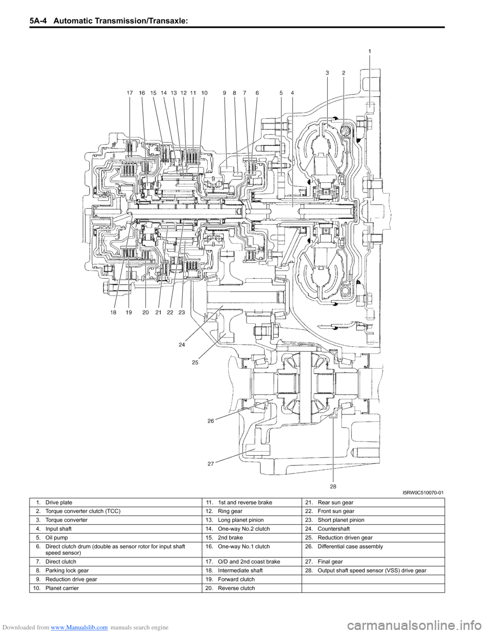
Downloaded from www.Manualslib.com manuals search engine 5A-4 Automatic Transmission/Transaxle:
I5RW0C510070-01
1. Drive plate 11. 1st and reverse brake 21. Rear sun gear
2. Torque converter clutch (TCC) 12. Ring gear 22. Front sun gear
3. Torque converter 13. Long planet pinion 23. Short planet pinion
4. Input shaft 14. One-way No.2 clutch 24. Countershaft
5. Oil pump 15. 2nd brake 25. Reduction driven gear
6. Direct clutch drum (double as sensor rotor for input shaft
speed sensor)16. One-way No.1 clutch 26. Differential case assembly
7. Direct clutch 17. O/D and 2nd coast brake 27. Final gear
8. Parking lock gear 18. Intermediate shaft 28. Output shaft speed sensor (VSS) drive gear
9. Reduction drive gear 19. Forward clutch
10. Planet carrier 20. Reverse clutch
Page 658 of 1556
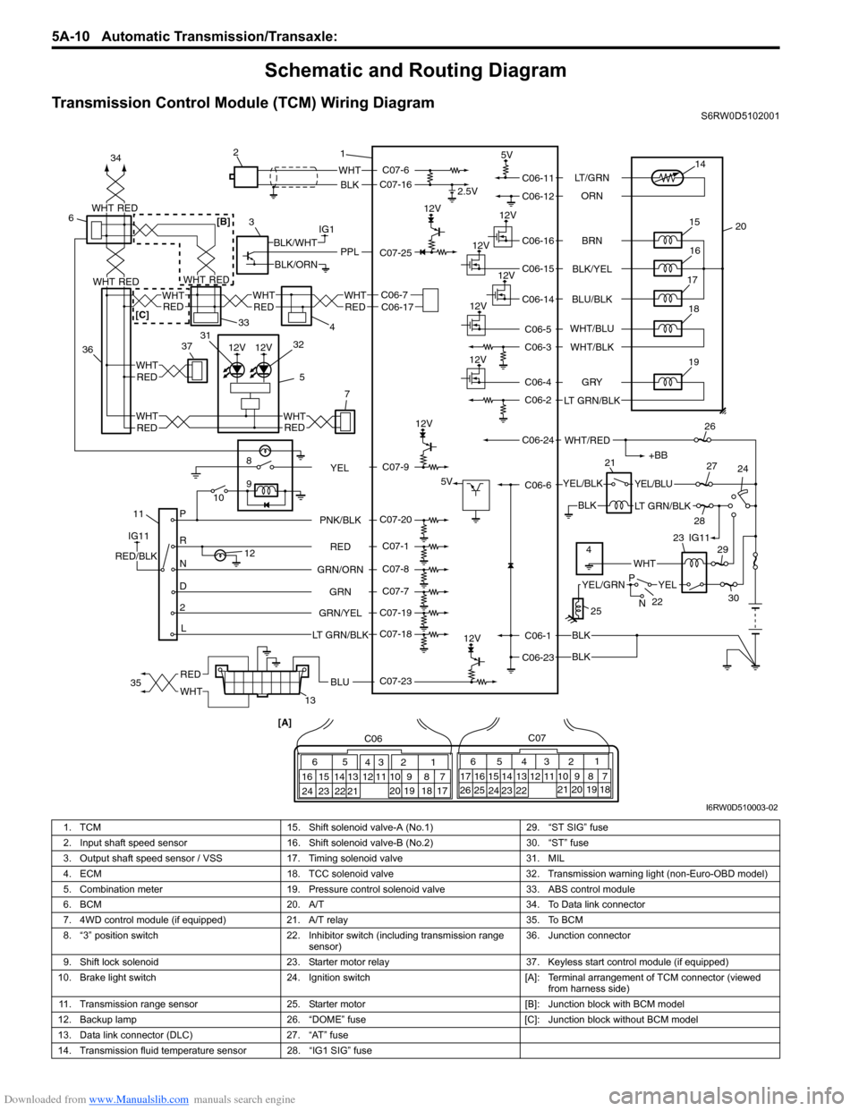
Downloaded from www.Manualslib.com manuals search engine 5A-10 Automatic Transmission/Transaxle:
Schematic and Routing Diagram
Transmission Control Module (TCM) Wiring DiagramS6RW0D5102001
12V
12V
12V
IG1
118
9
10
P
R
N
D
2
L12
2.5V
5V
12V
5V
12V
12V
12V
WHT
BLK
BLK
BLK
BLK
PPLBLK/WHT
BLK/ORN
IG11
RED/BLK
YEL/BLKYEL/BLU
LT GRN/BLK
+BB
WHT/RED
14
20 15
16
17
19
12V18
1 2
3
132126
24 27
28
29
30
65
16 15 14 13 12 1143
24 23 212210 9 8 721
19 20 18 17 C06
17 16
26 2515 14 65 342
13 12
23 22 2411 10 9
21 20 1987
18 1 C07
[A]
22
25
YELYEL/GRN
WHT
P
N
BRN LT/GRN
ORN
BLK/YEL
BLU/BLK
GRY
LT GRN/BLKWHT/BLU
WHT/BLK
C06-11
C06-12
C06-16
C06-15
C06-14
C06-4
C06-2
C06-1
C06-23C06-6 C06-24C06-5
C06-3
RED
GRN GRN/ORNPNK/BLK
GRN/YEL
LT GRN/BLKC07-6
C07-16
C07-23 C07-25
C07-20
C07-1
C07-8
C07-7
C07-19
C07-18
4IG11 23
C07-9
YEL
RED
WHTBLU35 34
3637
5REDWHT
7
WHT
RED
33
4
6
C06-7C06-17WHT
REDREDWHT
WHT
12V12V
WHTRED
WHTREDREDWHT
31
32
RED
WHTRED[B]
[C]
I6RW0D510003-02
1. TCM 15. Shift solenoid valve-A (No.1) 29. “ST SIG” fuse
2. Input shaft speed sensor 16. Shift solenoid valve-B (No.2) 30. “ST” fuse
3. Output shaft speed sensor / VSS 17. Timing solenoid valve 31. MIL
4. ECM 18. TCC solenoid valve 32. Transmission warning light (non-Euro-OBD model)
5. Combination meter 19. Pressure control solenoid valve 33. ABS control module
6. BCM 20. A/T 34. To Data link connector
7. 4WD control module (if equipped) 21. A/T relay 35. To BCM
8. “3” position switch 22. Inhibitor switch (including transmission range
sensor)36. Junction connector
9. Shift lock solenoid 23. Starter motor relay 37. Keyless start control module (if equipped)
10. Brake light switch 24. Ignition switch [A]: Terminal arrangement of TCM connector (viewed
from harness side)
11. Transmission range sensor 25. Starter motor [B]: Junction block with BCM model
12. Backup lamp 26. “DOME” fuse [C]: Junction block without BCM model
13. Data link connector (DLC) 27. “AT” fuse
14. Transmission fluid temperature sensor 28. “IG1 SIG” fuse
Page 663 of 1556
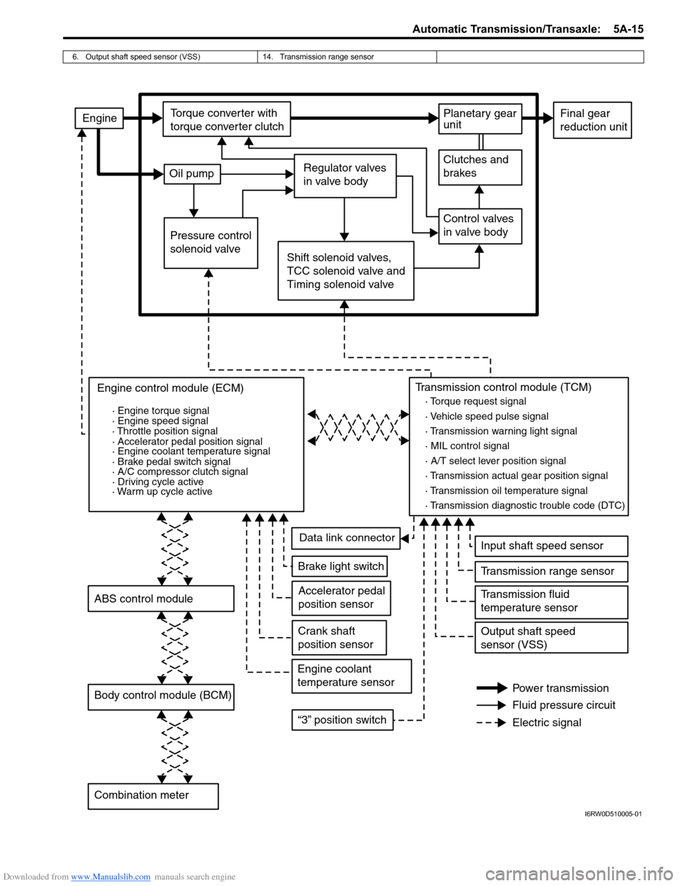
Downloaded from www.Manualslib.com manuals search engine Automatic Transmission/Transaxle: 5A-15
6. Output shaft speed sensor (VSS) 14. Transmission range sensor
EngineTorque converter with
torque converter clutch
Oil pumpRegulator valves
in valve body
Planetary gear
unit
Clutches and
brakes
Control valves
in valve body
Shift solenoid valves,
TCC solenoid valve and
Timing solenoid valve Pressure control
solenoid valve
Final gear
reduction unit
Engine control module (ECM)
Body control module (BCM)
Combination meter
· Engine torque signal
· Engine speed signal
Transmission control module (TCM)
· Torque request signal
· Throttle position signal
· Accelerator pedal position signal
· Engine coolant temperature signal
· Brake pedal switch signal
· Driving cycle active
· Warm up cycle active
Accelerator pedal
position sensor
Crank shaft
position sensor
Engine coolant
temperature sensor
Input shaft speed sensor
Brake light switch
“3” position switch
Transmission range sensor
Transmission fluid
temperature sensor
Output shaft speed
sensor (VSS)
Power transmission
Fluid pressure circuit
Electric signal
Data link connector
· Transmission diagnostic trouble code (DTC) · Vehicle speed pulse signal
· Transmission warning light signal
· A/T select lever position signal
· Transmission actual gear position signal
· Transmission oil temperature signal · MIL control signal
ABS control module
· A/C compressor clutch signal
I6RW0D510005-01
Page 668 of 1556
Downloaded from www.Manualslib.com manuals search engine 5A-20 Automatic Transmission/Transaxle:
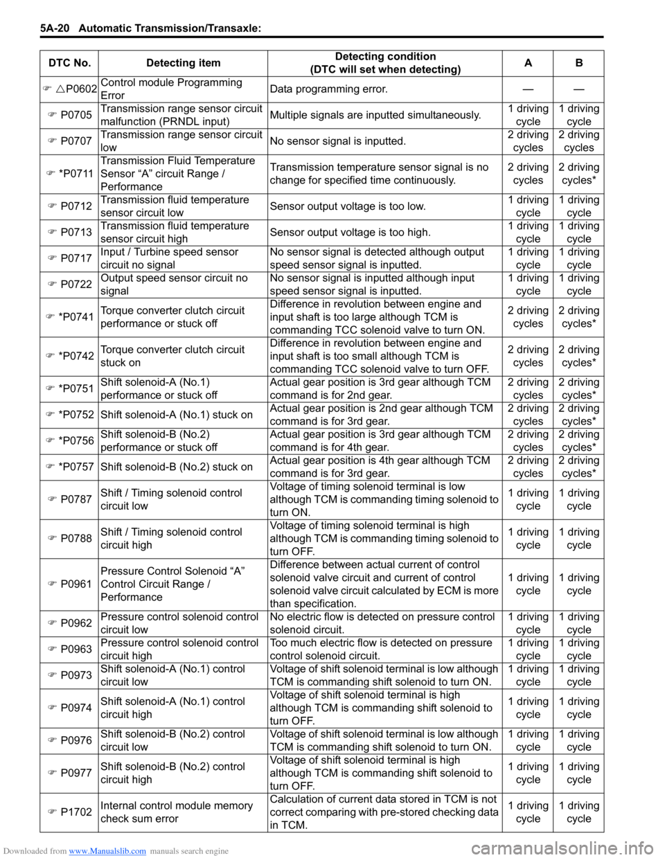
DTC No. Detecting itemDetecting condition
(DTC will set when detecting)AB
�) �UP0602Control module Programming
ErrorData programming error. — —
�) P0705Transmission range sensor circuit
malfunction (PRNDL input)Multiple signals are inputted simultaneously.1 driving
cycle1 driving
cycle
�) P0707Transmission range sensor circuit
lowNo sensor signal is inputted.2 driving
cycles2 driving
cycles
�) *P0711Transmission Fluid Temperature
Sensor “A” circuit Range /
PerformanceTransmission temperature sensor signal is no
change for specified time continuously.2 driving
cycles2 driving
cycles*
�) P0712Transmission fluid temperature
sensor circuit lowSensor output voltage is too low.1 driving
cycle1 driving
cycle
�) P0713Transmission fluid temperature
sensor circuit highSensor output voltage is too high.1 driving
cycle1 driving
cycle
�) P0717Input / Turbine speed sensor
circuit no signalNo sensor signal is detected although output
speed sensor signal is inputted.1 driving
cycle1 driving
cycle
�) P0722Output speed sensor circuit no
signalNo sensor signal is inputted although input
speed sensor signal is inputted.1 driving
cycle1 driving
cycle
�) *P0741Torque converter clutch circuit
performance or stuck offDifference in revolution between engine and
input shaft is too large although TCM is
commanding TCC solenoid valve to turn ON.2 driving
cycles2 driving
cycles*
�) *P0742Torque converter clutch circuit
stuck onDifference in revolution between engine and
input shaft is too small although TCM is
commanding TCC solenoid valve to turn OFF.2 driving
cycles2 driving
cycles*
�) *P0751
Shift solenoid-A (No.1)
performance or stuck offActual gear position is 3rd gear although TCM
command is for 2nd gear.2 driving
cycles2 driving
cycles*
�) *P0752 Shift solenoid-A (No.1) stuck onActual gear position is 2nd gear although TCM
command is for 3rd gear.2 driving
cycles2 driving
cycles*
�) *P0756Shift solenoid-B (No.2)
performance or stuck offActual gear position is 3rd gear although TCM
command is for 4th gear.2 driving
cycles2 driving
cycles*
�) *P0757 Shift solenoid-B (No.2) stuck onActual gear position is 4th gear although TCM
command is for 3rd gear.2 driving
cycles2 driving
cycles*
�) P0787Shift / Timing solenoid control
circuit lowVoltage of timing solenoid terminal is low
although TCM is commanding timing solenoid to
turn ON.1 driving
cycle1 driving
cycle
�) P0788Shift / Timing solenoid control
circuit highVoltage of timing solenoid terminal is high
although TCM is commanding timing solenoid to
turn OFF.1 driving
cycle1 driving
cycle
�) P0961Pressure Control Solenoid “A”
Control Circuit Range /
PerformanceDifference between actual current of control
solenoid valve circuit and current of control
solenoid valve circuit calculated by ECM is more
than specification.1 driving
cycle1 driving
cycle
�) P0962Pressure control solenoid control
circuit lowNo electric flow is detected on pressure control
solenoid circuit.1 driving
cycle1 driving
cycle
�) P0963Pressure control solenoid control
circuit highToo much electric flow is detected on pressure
control solenoid circuit.1 driving
cycle1 driving
cycle
�) P0973Shift solenoid-A (No.1) control
circuit lowVoltage of shift solenoid terminal is low although
TCM is commanding shift solenoid to turn ON.1 driving
cycle1 driving
cycle
�) P0974
Shift solenoid-A (No.1) control
circuit highVoltage of shift solenoid terminal is high
although TCM is commanding shift solenoid to
turn OFF.1 driving
cycle1 driving
cycle
�) P0976Shift solenoid-B (No.2) control
circuit lowVoltage of shift solenoid terminal is low although
TCM is commanding shift solenoid to turn ON.1 driving
cycle1 driving
cycle
�) P0977Shift solenoid-B (No.2) control
circuit highVoltage of shift solenoid terminal is high
although TCM is commanding shift solenoid to
turn OFF.1 driving
cycle1 driving
cycle
�) P1702Internal control module memory
check sum errorCalculation of current data stored in TCM is not
correct comparing with pre-stored checking data
in TCM.1 driving
cycle1 driving
cycle
Page 670 of 1556
Downloaded from www.Manualslib.com manuals search engine 5A-22 Automatic Transmission/Transaxle:
DTC ClearanceS6RW0D5104006
WARNING!
When performing a driving test, select a safe
place where there is neither any traffic nor
any traffic accident possibility and be very
careful during testing to avoid occurrence of
an accident.
After repair or replace malfunction part(s), clear all DTCs
by performing the following procedure.
1) Connect SUZUKI scan tool to data link connector in
the same manner as when making this connection
for “DTC Check”.
2) Turn ignition switch ON.3) Erase DTC and pending DTC according to
instructions displayed on scan tool. Refer to scan
tool operator’s manual for further details.
4) After completing the clearance, turn ignition switch
OFF and disconnect scan tool from data link
connector (DLC).
NOTE
DTC and freeze frame data stored in TCM
memory are also cleared in the following
cases. Be careful not to clear them before
keeping their record.
• When the same malfunction (DTC) is not
detected again during 40 engine warm-up
cycles.
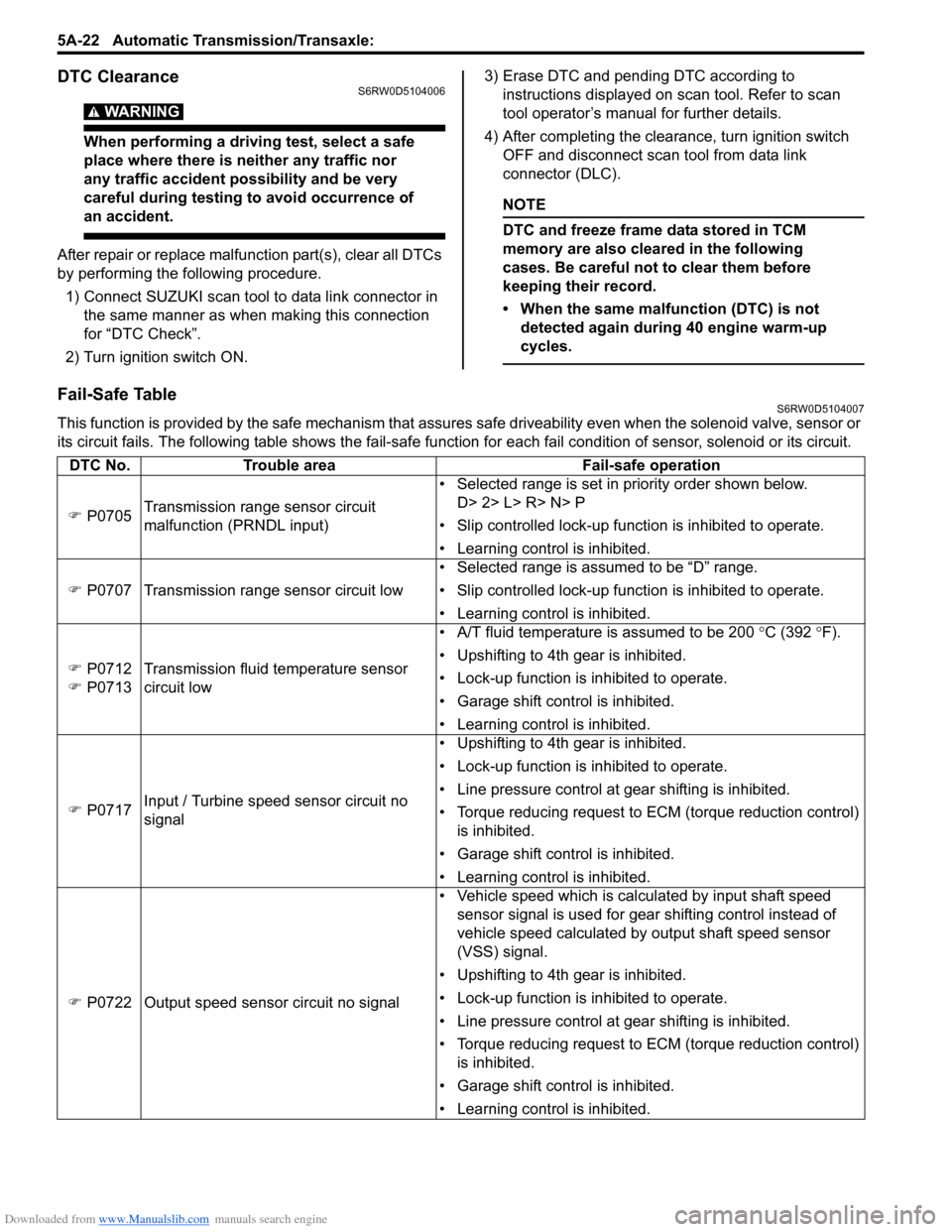
Fail-Safe TableS6RW0D5104007
This function is provided by the safe mechanism that assures safe driveability even when the solenoid valve, sensor or
its circuit fails. The following table shows the fail-safe function for each fail condition of sensor, solenoid or its circuit.
DTC No. Trouble area Fail-safe operation
�) P0705Transmission range sensor circuit
malfunction (PRNDL input)• Selected range is set in priority order shown below.
D> 2> L> R> N> P
• Slip controlled lock-up function is inhibited to operate.
• Learning control is inhibited.
�) P0707 Transmission range sensor circuit low• Selected range is assumed to be “D” range.
• Slip controlled lock-up function is inhibited to operate.
• Learning control is inhibited.
�) P0712
�) P0713Transmission fluid temperature sensor
circuit low• A/T fluid temperature is assumed to be 200 °C (392 °F).
• Upshifting to 4th gear is inhibited.
• Lock-up function is inhibited to operate.
• Garage shift control is inhibited.
• Learning control is inhibited.
�) P0717Input / Turbine speed sensor circuit no
signal• Upshifting to 4th gear is inhibited.
• Lock-up function is inhibited to operate.
• Line pressure control at gear shifting is inhibited.
• Torque reducing request to ECM (torque reduction control)
is inhibited.
• Garage shift control is inhibited.
• Learning control is inhibited.
�) P0722 Output speed sensor circuit no signal• Vehicle speed which is calculated by input shaft speed
sensor signal is used for gear shifting control instead of
vehicle speed calculated by output shaft speed sensor
(VSS) signal.
• Upshifting to 4th gear is inhibited.
• Lock-up function is inhibited to operate.
• Line pressure control at gear shifting is inhibited.
• Torque reducing request to ECM (torque reduction control)
is inhibited.
• Garage shift control is inhibited.
• Learning control is inhibited.
Page 672 of 1556
Downloaded from www.Manualslib.com manuals search engine 5A-24 Automatic Transmission/Transaxle:
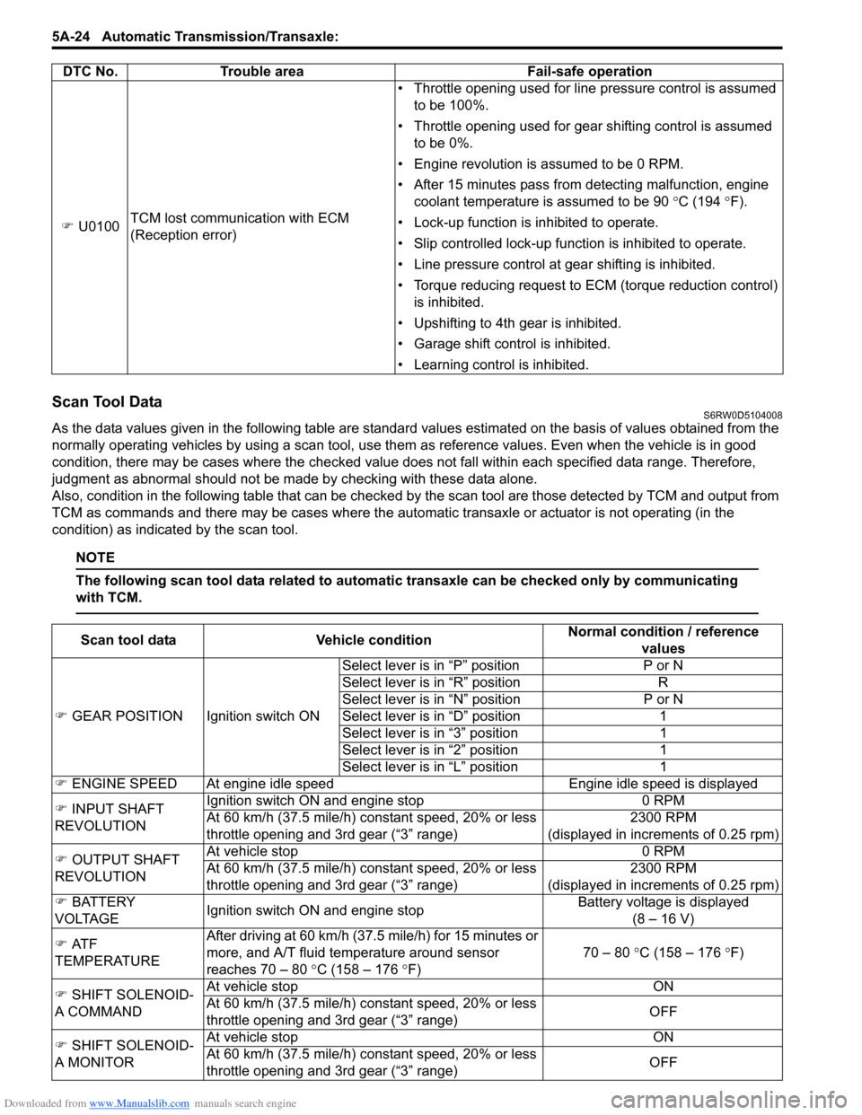
Scan Tool DataS6RW0D5104008
As the data values given in the following table are standard values estimated on the basis of values obtained from the
normally operating vehicles by using a scan tool, use them as reference values. Even when the vehicle is in good
condition, there may be cases where the checked value does not fall within each specified data range. Therefore,
judgment as abnormal should not be made by checking with these data alone.
Also, condition in the following table that can be checked by the scan tool are those detected by TCM and output from
TCM as commands and there may be cases where the automatic transaxle or actuator is not operating (in the
condition) as indicated by the scan tool.
NOTE
The following scan tool data related to automatic transaxle can be checked only by communicating
with TCM.
�) U0100TCM lost communication with ECM
(Reception error)• Throttle opening used for line pressure control is assumed
to be 100%.
• Throttle opening used for gear shifting control is assumed
to be 0%.
• Engine revolution is assumed to be 0 RPM.
• After 15 minutes pass from detecting malfunction, engine
coolant temperature is assumed to be 90 °C (194 °F).
• Lock-up function is inhibited to operate.
• Slip controlled lock-up function is inhibited to operate.
• Line pressure control at gear shifting is inhibited.
• Torque reducing request to ECM (torque reduction control)
is inhibited.
• Upshifting to 4th gear is inhibited.
• Garage shift control is inhibited.
• Learning control is inhibited. DTC No. Trouble area Fail-safe operation
Scan tool data Vehicle conditionNormal condition / reference
values
�) GEAR POSITION Ignition switch ONSelect lever is in “P” position P or N
Select lever is in “R” position R
Select lever is in “N” position P or N
Select lever is in “D” position 1
Select lever is in “3” position 1
Select lever is in “2” position 1
Select lever is in “L” position 1
�) ENGINE SPEED At engine idle speed Engine idle speed is displayed
�) INPUT SHAFT
REVOLUTIONIgnition switch ON and engine stop 0 RPM
At 60 km/h (37.5 mile/h) constant speed, 20% or less
throttle opening and 3rd gear (“3” range)2300 RPM
(displayed in increments of 0.25 rpm)
�) OUTPUT SHAFT
REVOLUTIONAt vehicle stop 0 RPM
At 60 km/h (37.5 mile/h) constant speed, 20% or less
throttle opening and 3rd gear (“3” range)2300 RPM
(displayed in increments of 0.25 rpm)
�) BATTERY
VOLTAGEIgnition switch ON and engine stopBattery voltage is displayed
(8 – 16 V)
�) AT F
TEMPERATUREAfter driving at 60 km/h (37.5 mile/h) for 15 minutes or
more, and A/T fluid temperature around sensor
reaches 70 – 80 °C (158 – 176 °F)70 – 80 °C (158 – 176 °F)
�) SHIFT SOLENOID-
A COMMANDAt vehicle stop ON
At 60 km/h (37.5 mile/h) constant speed, 20% or less
throttle opening and 3rd gear (“3” range)OFF
�) SHIFT SOLENOID-
A MONITORAt vehicle stop ON
At 60 km/h (37.5 mile/h) constant speed, 20% or less
throttle opening and 3rd gear (“3” range)OFF
Page 674 of 1556
Downloaded from www.Manualslib.com manuals search engine 5A-26 Automatic Transmission/Transaxle:
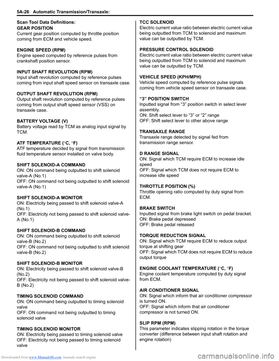
Scan Tool Data Definitions:
GEAR POSITION
Current gear position computed by throttle position
coming from ECM and vehicle speed.
ENGINE SPEED (RPM)
Engine speed computed by reference pulses from
crankshaft position sensor.
INPUT SHAFT REVOLUTION (RPM)
Input shaft revolution computed by reference pulses
coming from input shaft speed sensor on transaxle case.
OUTPUT SHAFT REVOLUTION (RPM)
Output shaft revolution computed by reference pulses
coming from output shaft speed sensor (VSS) on
transaxle case.
BATTERY VOLTAGE (V)
Battery voltage read by TCM as analog input signal by
TCM.
ATF TEMPERATURE (°C, °F)
ATF temperature decided by signal from transmission
fluid temperature sensor installed on valve body.
SHIFT SOLENOID-A COMMAND
ON: ON command being outputted to shift solenoid
valve-A (No.1)
OFF: ON command not being outputted to shift solenoid
valve-A (No.1)
SHIFT SOLENOID-A MONITOR
ON: Electricity being passed to shift solenoid valve-A
(No.1)
OFF: Electricity not being passed to shift solenoid valve-
A (No.1)
SHIFT SOLENOID-B COMMAND
ON: ON command being outputted to shift solenoid
valve-B (No.2)
OFF: ON command not being outputted to shift solenoid
valve-B (No.2)
SHIFT SOLENOID-B MONITOR
ON: Electricity being passed to shift solenoid valve-B
(No.2)
OFF: Electricity not being passed to shift solenoid valve-
B (No.2)
TIMING SOLENOID COMMAND
ON: ON command being outputted to timing solenoid
valve
OFF: ON command not being outputted to timing
solenoid valve
TIMING SOLENOID MONITOR
ON: Electricity being passed to timing solenoid valve
OFF: Electricity not being passed to timing solenoid
valveTCC SOLENOID
Electric current value ratio between electric current value
being outputted from TCM to solenoid and maximum
value can be outputted by TCM.
PRESSURE CONTROL SOLENOID
Electric current value ratio between electric current value
being outputted from TCM to solenoid and maximum
value can be outputted by TCM.
VEHICLE SPEED (KPH/MPH)
Vehicle speed computed by reference pulse signals
coming from vehicle speed sensor on transaxle case.
“3” POSITION SWITCH
Inputted signal from “3” position switch in select lever
assembly.
ON: Shift select lever to “3” or “2” range
OFF: Shift select lever to other above range
TRANSAXLE RANGE
Transaxle range detected by signal fed from
transmission range sensor.
D RANGE SIGNAL
ON: Signal which TCM require ECM to increase idle
speed
OFF: Signal which TCM does not require ECM to
increase idle speed
THROTTLE POSITION (%)
Throttle opening ratio computed by duty signal from
ECM.
BRAKE SWITCH
Inputted signal from brake light switch on pedal bracket.
ON: Brake pedal depressed
OFF: Brake pedal released
TORQUE REDUCTION SIGNAL
ON: Signal which TCM require ECM to reduce output
torque at shifting gear
OFF: Signal which TCM does not require ECM to reduce
output torque
ENGINE COOLANT TEMPERATURE (°C, °F)
Engine coolant temperature computed by duty signal
from ECM.
AIR CONDITIONER SIGNAL
ON: Signal which inform that air conditioner compressor
is turned ON.
OFF: Signal which inform that air conditioner
compressor is not turned ON.
SLIP RPM (RPM)
This parameter indicates slipping rotation in the torque
converter (difference between input shaft rotation and
engine rotation)
Page 676 of 1556
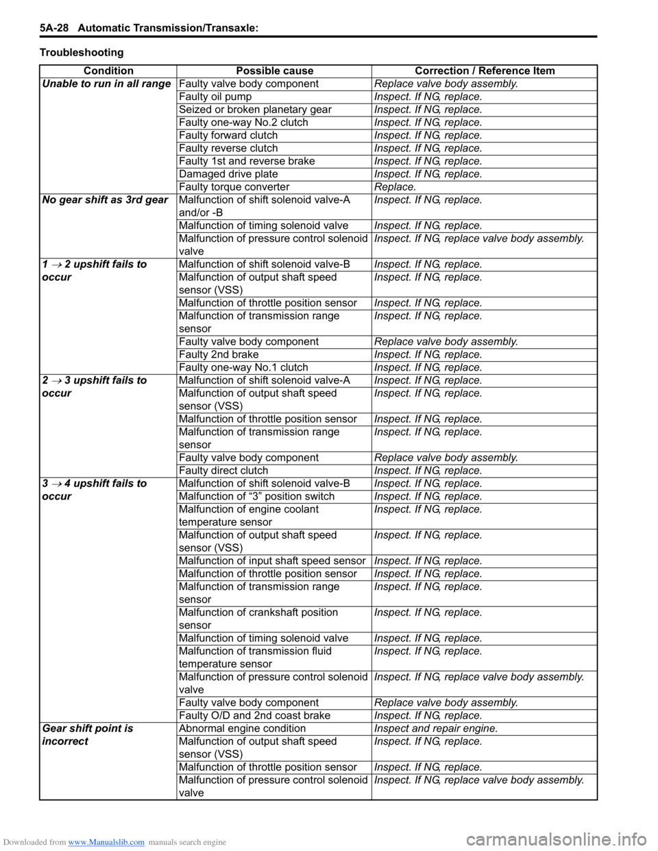
Downloaded from www.Manualslib.com manuals search engine 5A-28 Automatic Transmission/Transaxle:
Troubleshooting
Condition Possible cause Correction / Reference Item
Unable to run in all rangeFaulty valve body componentReplace valve body assembly.
Faulty oil pumpInspect. If NG, replace.
Seized or broken planetary gearInspect. If NG, replace.
Faulty one-way No.2 clutchInspect. If NG, replace.
Faulty forward clutchInspect. If NG, replace.
Faulty reverse clutchInspect. If NG, replace.
Faulty 1st and reverse brakeInspect. If NG, replace.
Damaged drive plateInspect. If NG, replace.
Faulty torque converterReplace.
No gear shift as 3rd gearMalfunction of shift solenoid valve-A
and/or -BInspect. If NG, replace.
Malfunction of timing solenoid valveInspect. If NG, replace.
Malfunction of pressure control solenoid
valveInspect. If NG, replace valve body assembly.
1
→ 2 upshift fails to
occurMalfunction of shift solenoid valve-BInspect. If NG, replace.
Malfunction of output shaft speed
sensor (VSS)Inspect. If NG, replace.
Malfunction of throttle position sensorInspect. If NG, replace.
Malfunction of transmission range
sensorInspect. If NG, replace.
Faulty valve body componentReplace valve body assembly.
Faulty 2nd brakeInspect. If NG, replace.
Faulty one-way No.1 clutchInspect. If NG, replace.
2
→ 3 upshift fails to
occurMalfunction of shift solenoid valve-AInspect. If NG, replace.
Malfunction of output shaft speed
sensor (VSS)Inspect. If NG, replace.
Malfunction of throttle position sensorInspect. If NG, replace.
Malfunction of transmission range
sensorInspect. If NG, replace.
Faulty valve body componentReplace valve body assembly.
Faulty direct clutchInspect. If NG, replace.
3
→ 4 upshift fails to
occurMalfunction of shift solenoid valve-BInspect. If NG, replace.
Malfunction of “3” position switchInspect. If NG, replace.
Malfunction of engine coolant
temperature sensorInspect. If NG, replace.
Malfunction of output shaft speed
sensor (VSS)Inspect. If NG, replace.
Malfunction of input shaft speed sensorInspect. If NG, replace.
Malfunction of throttle position sensorInspect. If NG, replace.
Malfunction of transmission range
sensorInspect. If NG, replace.
Malfunction of crankshaft position
sensorInspect. If NG, replace.
Malfunction of timing solenoid valveInspect. If NG, replace.
Malfunction of transmission fluid
temperature sensorInspect. If NG, replace.
Malfunction of pressure control solenoid
valveInspect. If NG, replace valve body assembly.
Faulty valve body componentReplace valve body assembly.
Faulty O/D and 2nd coast brakeInspect. If NG, replace.
Gear shift point is
incorrectAbnormal engine conditionInspect and repair engine.
Malfunction of output shaft speed
sensor (VSS)Inspect. If NG, replace.
Malfunction of throttle position sensorInspect. If NG, replace.
Malfunction of pressure control solenoid
valveInspect. If NG, replace valve body assembly.
Page 677 of 1556
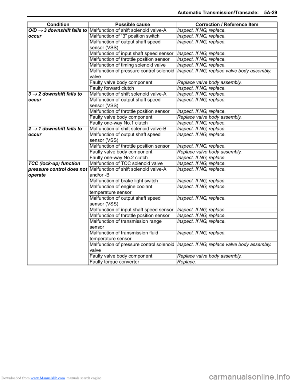
Downloaded from www.Manualslib.com manuals search engine Automatic Transmission/Transaxle: 5A-29
O/D → 3 downshift fails to
occurMalfunction of shift solenoid valve-AInspect. If NG, replace.
Malfunction of “3” position switchInspect. If NG, replace.
Malfunction of output shaft speed
sensor (VSS)Inspect. If NG, replace.
Malfunction of input shaft speed sensorInspect. If NG, replace.
Malfunction of throttle position sensorInspect. If NG, replace.
Malfunction of timing solenoid valveInspect. If NG, replace.
Malfunction of pressure control solenoid
valveInspect. If NG, replace valve body assembly.
Faulty valve body componentReplace valve body assembly.
Faulty forward clutchInspect. If NG, replace.
3
→ 2 downshift fails to
occurMalfunction of shift solenoid valve-AInspect. If NG, replace.
Malfunction of output shaft speed
sensor (VSS)Inspect. If NG, replace.
Malfunction of throttle position sensorInspect. If NG, replace.
Faulty valve body componentReplace valve body assembly.
Faulty one-way No.1 clutchInspect. If NG, replace.
2
→ 1 downshift fails to
occurMalfunction of shift solenoid valve-BInspect. If NG, replace.
Malfunction of output shaft speed
sensor (VSS)Inspect. If NG, replace.
Malfunction of throttle position sensorInspect. If NG, replace.
Faulty valve body componentReplace valve body assembly.
Faulty one-way No.2 clutchInspect. If NG, replace.
TCC (lock-up) function
pressure control does not
operateMalfunction of TCC solenoid valveInspect. If NG, replace.
Malfunction of shift solenoid valve-A
and/or -BInspect. If NG, replace.
Malfunction of brake light switchInspect. If NG, replace.
Malfunction of engine coolant
temperature sensorInspect. If NG, replace.
Malfunction of output shaft speed
sensor (VSS)Inspect. If NG, replace.
Malfunction of input shaft speed sensorInspect. If NG, replace.
Malfunction of throttle position sensorInspect. If NG, replace.
Malfunction of transmission range
sensorInspect. If NG, replace.
Malfunction of transmission fluid
temperature sensorInspect. If NG, replace.
Malfunction of pressure control solenoid
valveInspect. If NG, replace valve body assembly.
Faulty valve body componentReplace valve body assembly.
Faulty torque converterReplace. Condition Possible cause Correction / Reference Item