Output speed sensor SUZUKI SX4 2006 1.G Service Repair Manual
[x] Cancel search | Manufacturer: SUZUKI, Model Year: 2006, Model line: SX4, Model: SUZUKI SX4 2006 1.GPages: 1556, PDF Size: 37.31 MB
Page 809 of 1556
Downloaded from www.Manualslib.com manuals search engine Automatic Transmission/Transaxle: 5A-161
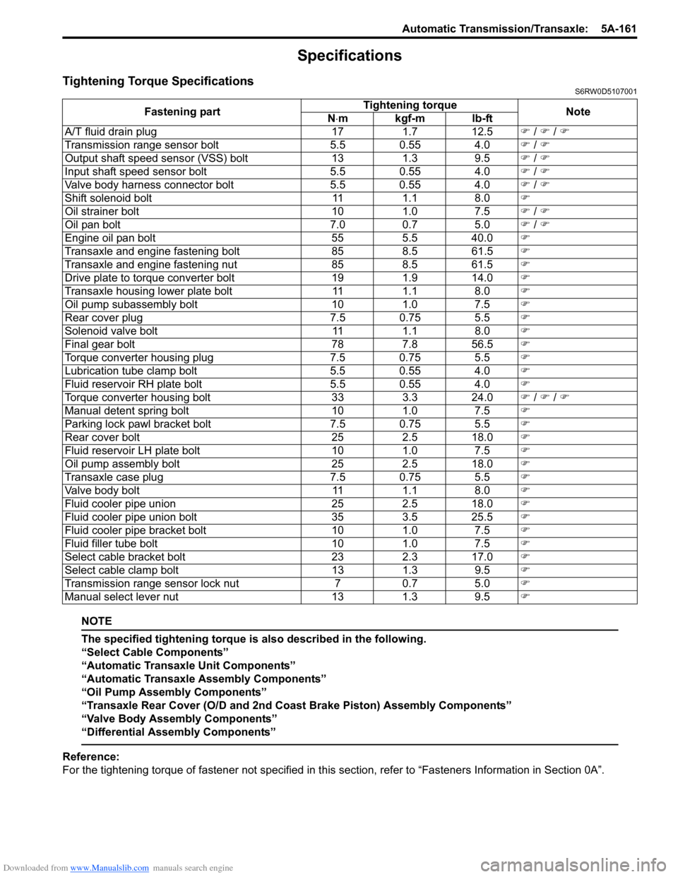
Specifications
Tightening Torque SpecificationsS6RW0D5107001
NOTE
The specified tightening torque is also described in the following.
“Select Cable Components”
“Automatic Transaxle Unit Components”
“Automatic Transaxle Assembly Components”
“Oil Pump Assembly Components”
“Transaxle Rear Cover (O/D and 2nd Coast Brake Piston) Assembly Components”
“Valve Body Assembly Components”
“Differential Assembly Components”
Reference:
For the tightening torque of fastener not specified in this section, refer to “Fasteners Information in Section 0A”. Fastening partTightening torque
Note
N⋅mkgf-mlb-ft
A/T fluid drain plug 17 1.7 12.5�) / �) / �)
Transmission range sensor bolt 5.5 0.55 4.0�) / �)
Output shaft speed sensor (VSS) bolt 13 1.3 9.5�) / �)
Input shaft speed sensor bolt 5.5 0.55 4.0�) / �)
Valve body harness connector bolt 5.5 0.55 4.0�) / �)
Shift solenoid bolt 11 1.1 8.0�)
Oil strainer bolt 10 1.0 7.5�) / �)
Oil pan bolt 7.0 0.7 5.0�) / �)
Engine oil pan bolt 55 5.5 40.0�)
Transaxle and engine fastening bolt 85 8.5 61.5�)
Transaxle and engine fastening nut 85 8.5 61.5�)
Drive plate to torque converter bolt 19 1.9 14.0�)
Transaxle housing lower plate bolt 11 1.1 8.0�)
Oil pump subassembly bolt 10 1.0 7.5�)
Rear cover plug 7.5 0.75 5.5�)
Solenoid valve bolt 11 1.1 8.0�)
Final gear bolt 78 7.8 56.5�)
Torque converter housing plug 7.5 0.75 5.5�)
Lubrication tube clamp bolt 5.5 0.55 4.0�)
Fluid reservoir RH plate bolt 5.5 0.55 4.0�)
Torque converter housing bolt 33 3.3 24.0�) / �) / �)
Manual detent spring bolt 10 1.0 7.5�)
Parking lock pawl bracket bolt 7.5 0.75 5.5�)
Rear cover bolt 25 2.5 18.0�)
Fluid reservoir LH plate bolt 10 1.0 7.5�)
Oil pump assembly bolt 25 2.5 18.0�)
Transaxle case plug 7.5 0.75 5.5�)
Valve body bolt 11 1.1 8.0�)
Fluid cooler pipe union 25 2.5 18.0�)
Fluid cooler pipe union bolt 35 3.5 25.5�)
Fluid cooler pipe bracket bolt 10 1.0 7.5�)
Fluid filler tube bolt 10 1.0 7.5�)
Select cable bracket bolt 23 2.3 17.0�)
Select cable clamp bolt 13 1.3 9.5�)
Transmission range sensor lock nut 7 0.7 5.0�)
Manual select lever nut 13 1.3 9.5�)
Page 884 of 1556
![SUZUKI SX4 2006 1.G Service Repair Manual Downloaded from www.Manualslib.com manuals search engine 6C-4 Power Assisted Steering System:
Schematic and Routing Diagram
EPS System Wiring Circuit DiagramS6RW0D6302001
[A]
123
45
3 21
4
567
8
9 11 SUZUKI SX4 2006 1.G Service Repair Manual Downloaded from www.Manualslib.com manuals search engine 6C-4 Power Assisted Steering System:
Schematic and Routing Diagram
EPS System Wiring Circuit DiagramS6RW0D6302001
[A]
123
45
3 21
4
567
8
9 11](/img/20/7612/w960_7612-883.png)
Downloaded from www.Manualslib.com manuals search engine 6C-4 Power Assisted Steering System:
Schematic and Routing Diagram
EPS System Wiring Circuit DiagramS6RW0D6302001
[A]
123
45
3 21
4
567
8
9 11
10 12 13
141516
17 18 19201
2
[B]
1
2
[C] [D]
10 9 8 7654 3 21
16 15 14 13 12 11
26 25 24 2322 21 20 19 18 17
32 31 30 29 28 27
[F][E]
12
BRN RED/
BLU GRY LT GRN/
BLK
BLK
RED
WHT GRN
BLK
E11-1
E11-5
E11-14
E11-12
[J]:E01-44E01-4
[J]:E01-27E01-26
E12-1
E12-2
E11-10E11-8
E11-9
E11-19
E13-1 GRN
GRY
GRN
WHT
G241-25G241-31
RED/BLK
11
12
1314 3 18
20
21
7 19
4 12
22
12V
E13-2BLK
9V
REDE11-20
12V
12V
E61-2
E61-1
610
55
5V
8
E11-115V
PPL
E11-4
9
23
+BB
BLU/
WHTE04-9
1524YELE11-18E31-5
E31-2
E31-39V
3V
E31-4
E31-1IG11617
C07-25
[H]
[G]
G04-15
[I]:G04-22
25L313-3
[I]
I6RW0D630001-01
[A]: P/S control module connector No.1 “E11” (viewed from harness side) 3. Junction block assembly 15. BCM
[B]: P/S control module connector No.2 “E13” (viewed from harness side) 4. Main fuse 16. Output shaft speed sensor
[C]: P/S control module connector No.3 “E12” (viewed from harness side) 5. Front (left/right) wheel speed sensor 17. TCM
[D]: Combination meter connector “G241” (viewed from harness side) 6. ABS control module 18. Individual circuit fuse box No.1
[E]: Torque sensor connector “E31” (viewed from harness side) 7. Combination meter 19. “IGN” fuse
[F]: Motor connector “E61” (viewed from harness side) 8. “EPS” warning light 20. “P/S” fuse
[G]: M/T model 9. Data link connector (DLC) 21. “IG1 SIG” fuse
[H]: A/T model 10. ECM 22. “MTR” fuse
[I]: Junction block without BCM model (Taiwan model) 11. P/S control module 23. To ABS control module
[J]: M15A engine with 4A/T equipped with slip control model (Hong Kong
model)12. P/S motor 24. To HVAC control module
1. Main fuse box 13. Shield 25. To SDM
2. Ignition switch 14. Torque sensor (built into steering gear case)
Page 885 of 1556
Downloaded from www.Manualslib.com manuals search engine Power Assisted Steering System: 6C-5
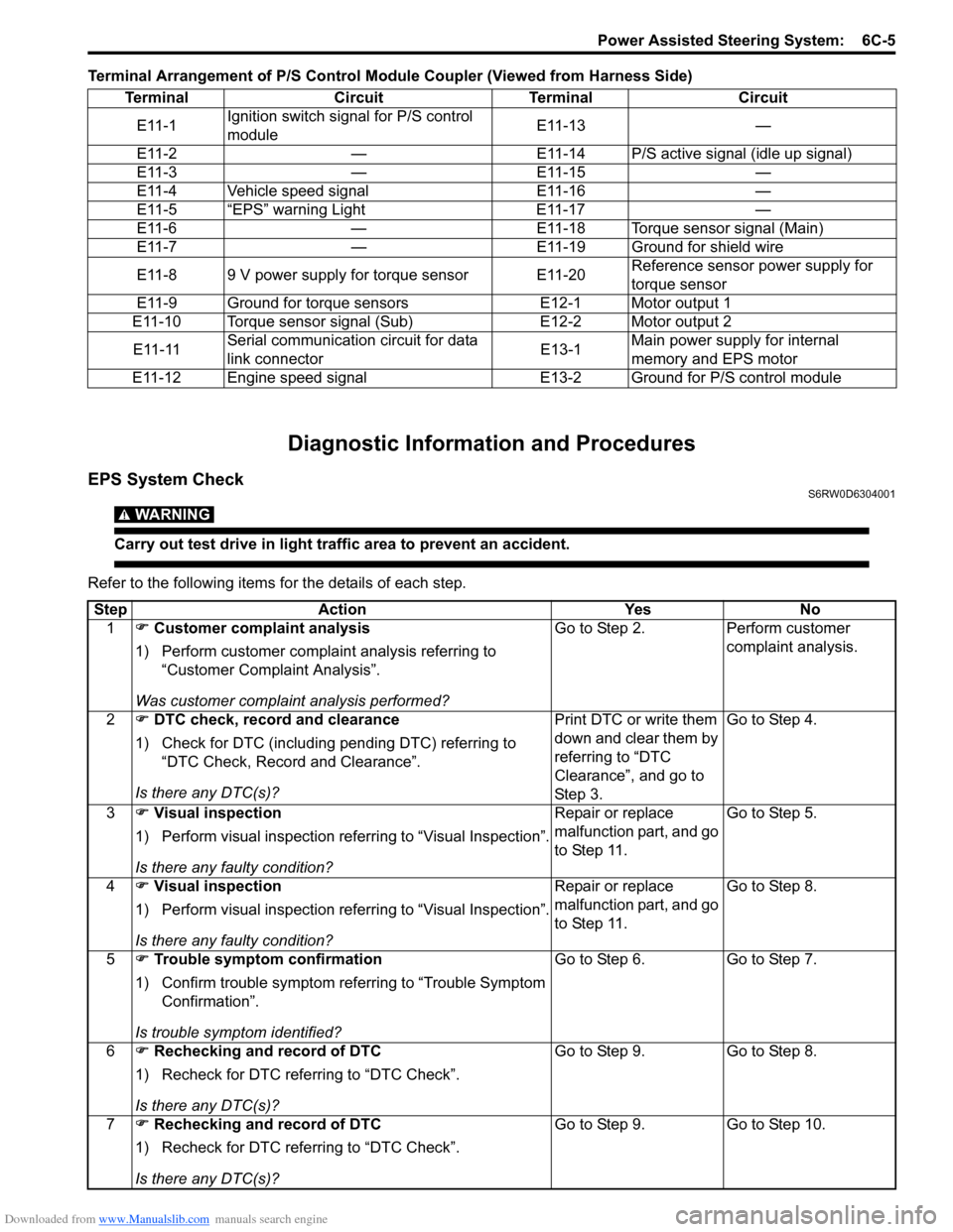
Terminal Arrangement of P/S Control Module Coupler (Viewed from Harness Side)
Diagnostic Information and Procedures
EPS System CheckS6RW0D6304001
WARNING!
Carry out test drive in light traffic area to prevent an accident.
Refer to the following items for the details of each step.Terminal Circuit Terminal Circuit
E11-1Ignition switch signal for P/S control
moduleE11-13 —
E11-2 — E11-14 P/S active signal (idle up signal)
E11-3 — E11-15 —
E11-4 Vehicle speed signal E11-16 —
E11-5 “EPS” warning Light E11-17 —
E11-6 — E11-18 Torque sensor signal (Main)
E11-7 — E11-19 Ground for shield wire
E11-8 9 V power supply for torque sensor E11-20Reference sensor power supply for
torque sensor
E11-9 Ground for torque sensors E12-1 Motor output 1
E11-10 Torque sensor signal (Sub) E12-2 Motor output 2
E11-11Serial communication circuit for data
link connectorE13-1Main power supply for internal
memory and EPS motor
E11-12 Engine speed signal E13-2 Ground for P/S control module
Step Action Yes No
1�) Customer complaint analysis
1) Perform customer complaint analysis referring to
“Customer Complaint Analysis”.
Was customer complaint analysis performed?Go to Step 2. Perform customer
complaint analysis.
2�) DTC check, record and clearance
1) Check for DTC (including pending DTC) referring to
“DTC Check, Record and Clearance”.
Is there any DTC(s)?Print DTC or write them
down and clear them by
referring to “DTC
Clearance”, and go to
St ep 3 .Go to Step 4.
3�) Visual inspection
1) Perform visual inspection referring to “Visual Inspection”.
Is there any faulty condition?Repair or replace
malfunction part, and go
to Step 11.Go to Step 5.
4�) Visual inspection
1) Perform visual inspection referring to “Visual Inspection”.
Is there any faulty condition?Repair or replace
malfunction part, and go
to Step 11.Go to Step 8.
5�) Trouble symptom confirmation
1) Confirm trouble symptom referring to “Trouble Symptom
Confirmation”.
Is trouble symptom identified?Go to Step 6. Go to Step 7.
6�) Rechecking and record of DTC
1) Recheck for DTC referring to “DTC Check”.
Is there any DTC(s)?Go to Step 9. Go to Step 8.
7�) Rechecking and record of DTC
1) Recheck for DTC referring to “DTC Check”.
Is there any DTC(s)?Go to Step 9. Go to Step 10.
Page 892 of 1556
Downloaded from www.Manualslib.com manuals search engine 6C-12 Power Assisted Steering System:
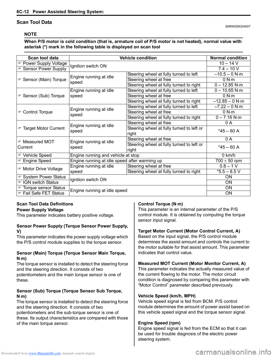
Scan Tool DataS6RW0D6304007
NOTE
When P/S motor is cold condition (that is, armature coil of P/S motor is not heated), normal value with
asterisk (*) mark in the following table is displayed on scan tool
Scan Tool Data Definitions
Power Supply Voltage
This parameter indicates battery positive voltage.
Sensor Power Supply (Torque Sensor Power Supply,
V)
This parameter indicates the power supply voltage which
the P/S control module supplies to the torque sensor.
Sensor (Main) Torque (Torque Sensor Main Torque,
N⋅m)
The torque sensor is installed to detect the steering force
and the steering direction. It consists of two
potentiometers and the main torque sensor is one of
these.
Sensor (Sub) Torque (Torque Sensor Sub Torque,
N⋅m)
The torque sensor is installed to detect the steering force
and the steering direction. It consists of two
potentiometers and the sub-torque sensor is one of
these. Its output characteristics are compared with those
of the main torque sensor.Control Torque (N⋅m)
This parameter is an internal parameter of the P/S
control module. It is obtained by computing the torque
sensor input signal.
Target Motor Current (Motor Control Current, A)
Based on the input signal, the P/S control module
determines the assist amount and controls the current to
the motor suitable for that assist amount. This parameter
indicates that control value.
Measured MOT Current (Motor Monitor Current, A)
This parameter indicates the actually measured value of
the current flowing to the motor. The motor circuit
condition is diagnosed by comparing this parameter with
“Motor Control” parameter described previously.
Vehicle Speed (km/h, MPH)
Vehicle speed signal is fed from BCM. P/S control
module determines the amount of power assist based on
this vehicle speed signal and the torque sensor signal.
Engine Speed (rpm)
Engine speed signal is fed from the ECM so that it can
be used for trouble diagnosis of the electric power
steering system. Scan tool data Vehicle condition Normal condition
�) Power Supply Voltage
Ignition switch ON10 – 14 V
�) Sensor Power Supply7.4 – 10 V
�) Sensor (Main) TorqueEngine running at idle
speedSteering wheel at fully turned to left –10.5 – 0 N⋅m
Steering wheel at free 0 N⋅m
Steering wheel at fully turned to right 0 – 12.85 N⋅m
�) Sensor (Sub) Torque Engine running at idle
speedSteering wheel at fully turned to left 0 – 10.65 N⋅m
Steering wheel at free 0 N⋅m
Steering wheel at fully turned to right –12.85 – 0 N⋅m
�) Control TorqueEngine running at idle
speedSteering wheel at fully turned to left –7.22 – 0 N⋅m
Steering wheel at free 0 N⋅m
Steering wheel at fully turned to right 0 – 7.16 N⋅m
�) Target Motor CurrentEngine running at idle
speedSteering wheel at free 0 A
Steering wheel at fully turned to left or
right*45 – 60 A
�) Measured MOT
Current
Engine running at idle
speedSteering wheel at free 0 A
Steering wheel at fully turned to left or
right*45 – 60 A
�) Vehicle Speed Engine running and vehicle at stop 0 km/h
�) Engine Speed Engine running at idle speed after warming up 700 ± 50 rpm
�) Motor Drive VoltageEngine running at idle
speedSteering wheel at free 0.8 – 1 V
Steering wheel at fully turned to right *5.5 – 8.5 V
�) System Power Status
Ignition switch ONON
�) IGN switch StatusON
�) Torque sensor Status
Engine running at idle speedON
�) Fail Safe FET StatusON
Page 893 of 1556
Downloaded from www.Manualslib.com manuals search engine Power Assisted Steering System: 6C-13
Motor Drive Voltage (V)
This parameter indicates the voltage between motor
terminals.
System Power Status (EPS System Power, ON, OFF)
This parameter indicates input status of EPS system
power supply.
IGN switch Status (ON, OFF)
This parameter indicates the condition of the power
supply through the ignition switch.Torque sensor Status (ON, OFF)
This parameter indicates the output status of the torque
sensor power supply.
Fail Safe FET Status (ON, OFF)
This parameter indicates the status of the motor drive
power supply circuit.
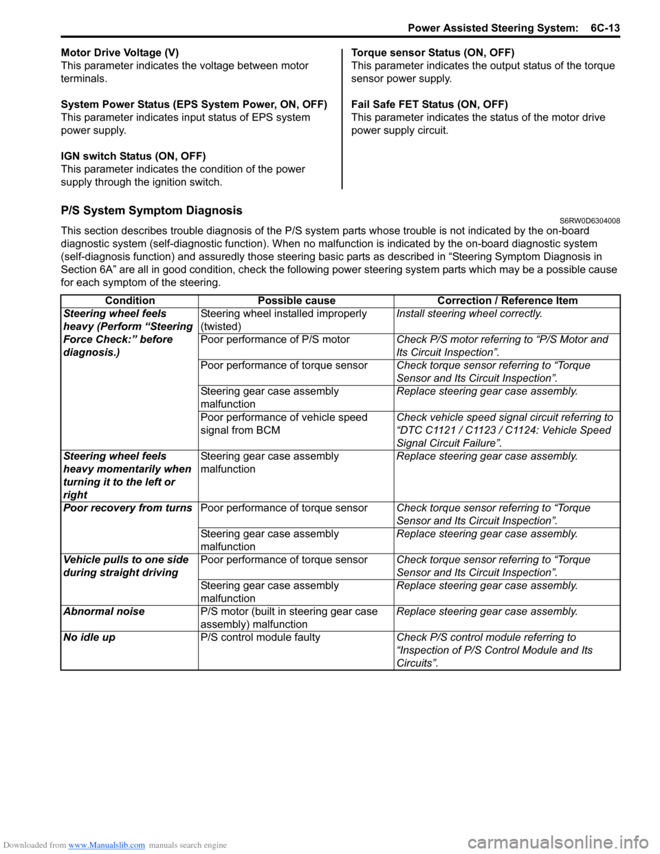
P/S System Symptom DiagnosisS6RW0D6304008
This section describes trouble diagnosis of the P/S system parts whose trouble is not indicated by the on-board
diagnostic system (self-diagnostic function). When no malfunction is indicated by the on-board diagnostic system
(self-diagnosis function) and assuredly those steering basic parts as described in “Steering Symptom Diagnosis in
Section 6A” are all in good condition, check the following power steering system parts which may be a possible cause
for each symptom of the steering.
Condition Possible cause Correction / Reference Item
Steering wheel feels
heavy (Perform “Steering
Force Check:” before
diagnosis.)Steering wheel installed improperly
(twisted)Install steering wheel correctly.
Poor performance of P/S motorCheck P/S motor referring to “P/S Motor and
Its Circuit Inspection”.
Poor performance of torque sensorCheck torque sensor referring to “Torque
Sensor and Its Circuit Inspection”.
Steering gear case assembly
malfunctionReplace steering gear case assembly.
Poor performance of vehicle speed
signal from BCMCheck vehicle speed signal circuit referring to
“DTC C1121 / C1123 / C1124: Vehicle Speed
Signal Circuit Failure”.
Steering wheel feels
heavy momentarily when
turning it to the left or
rightSteering gear case assembly
malfunctionReplace steering gear case assembly.
Poor recovery from turnsPoor performance of torque sensorCheck torque sensor referring to “Torque
Sensor and Its Circuit Inspection”.
Steering gear case assembly
malfunctionReplace steering gear case assembly.
Vehicle pulls to one side
during straight drivingPoor performance of torque sensorCheck torque sensor referring to “Torque
Sensor and Its Circuit Inspection”.
Steering gear case assembly
malfunctionReplace steering gear case assembly.
Abnormal noiseP/S motor (built in steering gear case
assembly) malfunctionReplace steering gear case assembly.
No idle upP/S control module faultyCheck P/S control module referring to
“Inspection of P/S Control Module and Its
Circuits”.
Page 902 of 1556
Downloaded from www.Manualslib.com manuals search engine 6C-22 Power Assisted Steering System:
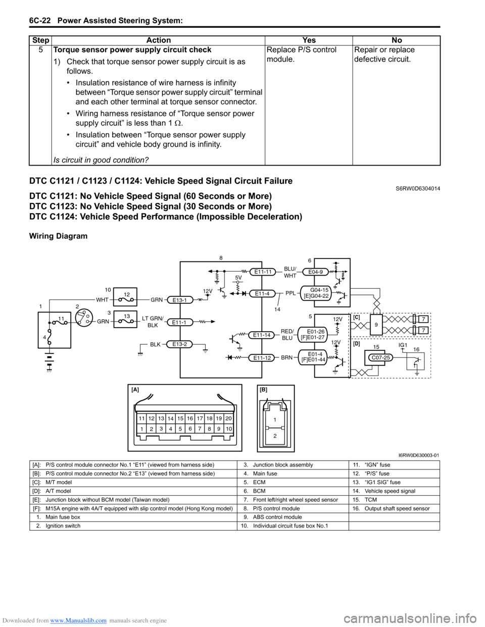
DTC C1121 / C1123 / C1124: Vehicle Speed Signal Circuit FailureS6RW0D6304014
DTC C1121: No Vehicle Speed Signal (60 Seconds or More)
DTC C1123: No Vehicle Speed Signal (30 Seconds or More)
DTC C1124: Vehicle Speed Performance (Impossible Deceleration)
Wiring Diagram5Torque sensor power supply circuit check
1) Check that torque sensor power supply circuit is as
follows.
• Insulation resistance of wire harness is infinity
between “Torque sensor power supply circuit” terminal
and each other terminal at torque sensor connector.
• Wiring harness resistance of “Torque sensor power
supply circuit” is less than 1 Ω.
• Insulation between “Torque sensor power supply
circuit” and vehicle body ground is infinity.
Is circuit in good condition?Replace P/S control
module.Repair or replace
defective circuit. Step Action Yes No
[A]
123
4567
8
9 11
10 12 13
141516
17 18 1920
1
2
[B]
BRN RED/
BLU LT GRN/
BLK
E11-1
E11-14
E11-12
E13-1 GRN
GRN
WHT
8
3 10
12
13
11
4 1
2
12V
E13-2BLK
12V
12V
9 5
77
E11-11
G04-15
[E]G04-22
5V
PPL
E11-4
BLU/
WHTE04-9
6
14
IG11615
C07-25
[D][C]
[F]E01-44E01-4
[F]E01-27E01-26
I6RW0D630003-01
[A]: P/S control module connector No.1 “E11” (viewed from harness side) 3. Junction block assembly 11. “IGN” fuse
[B]: P/S control module connector No.2 “E13” (viewed from harness side) 4. Main fuse 12. “P/S” fuse
[C]: M/T model 5. ECM 13. “IG1 SIG” fuse
[D]: A/T model 6. BCM 14. Vehicle speed signal
[E]: Junction block without BCM model (Taiwan model) 7. Front left/right wheel speed sensor 15. TCM
[F]: M15A engine with 4A/T equipped with slip control model (Hong Kong model) 8. P/S control module 16. Output shaft speed sensor
1. Main fuse box 9. ABS control module
2. Ignition switch 10. Individual circuit fuse box No.1
Page 923 of 1556

Downloaded from www.Manualslib.com manuals search engine Power Assisted Steering System: 6C-43
8) Using ammeter (2), check that P/S motor current (1)
is as following table with idling engine. If check result
is not satisfactory, check P/S control module for
torque sensor signal and P/S motor output referring
to “Inspection of P/S Control Module and Its
Circuits”. If they are OK, replace steering gear case
assembly.
NOTE
When P/S motor is cold condition (that is,
armature coil of P/S motor is not heated),
motor current in the following table can be
measured
Motor current at hoisted vehicle (reference
value)
Specifications
Tightening Torque SpecificationsS6RW0D6307001
NOTE
The specified tightening torque is also described in the following.
“Steering Gear Case Assembly Components”
Reference:
For the tightening torque of fastener not specified in this section, refer to “Fasteners Information in Section 0A”. ConditionWhen
steering
wheel is left
at straight
position: [A]When steering
wheel is turned
left or right by
turning speed
with 90° /sec:
[B]When
steering
wheel is
kept fully
turned left
or right
until it
stops.: [C]
Motor
currentApprox. 0 A Approx. 0 – 5 AApprox.
45 – 60 A
3. P/S control module
1
32
E12-1
E12-2
[C][A]
[B] [B]
I7RW01632012-01
Fastening partTightening torque
Note
N⋅mkgf-mlb-ft
Tie-rod end nut 45 4.5 32.5�)
Tie-rod end lock nut 45 4.5 32.5�)
Wheel bolt 85 8.5 61.5�)
Steering gear case mounting bolt 70 7.0 51.0�)
Steering lower shaft assembly upper joint bolt 25 2.5 18.5�)
Steering lower shaft assembly lower joint bolt 25 2.5 18.5�)
Tie-rod 75 7.5 54.5�)
Earth cable bolt 4.0 0.4 2.8�)
Rack damper screw Tighten 25 N⋅m (2.5 kgf-m, 18.0 lb-ft) and
loosen 180° and then tighten 3.9 N⋅m (0.39
kgf-m, 3.0 lb-ft) and turn it back by 10° or
less by the specified procedure.�)
Rotation torque of pinion 2.2 0.22 1.5�)
Steering rack damper lock nut 60 6.0 43.5�)
Page 925 of 1556
Downloaded from www.Manualslib.com manuals search engine Table of Contents 7- i
7
Section 7
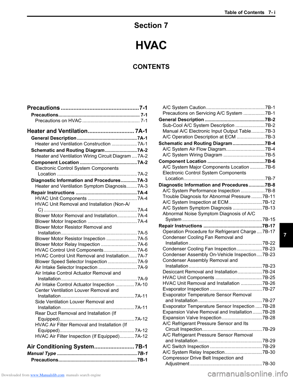
CONTENTS
HVAC
Precautions ................................................. 7-1
Precautions............................................................. 7-1
Precautions on HVAC ........................................... 7-1
Heater and Ventilation............................. 7A-1
General Description ............................................. 7A-1
Heater and Ventilation Construction ................... 7A-1
Schematic and Routing Diagram ........................ 7A-2
Heater and Ventilation Wiring Circuit Diagram .... 7A-2
Component Location ........................................... 7A-2
Electronic Control System Components
Location ............................................................ 7A-2
Diagnostic Information and Procedures ............ 7A-3
Heater and Ventilation Symptom Diagnosis........ 7A-3
Repair Instructions .............................................. 7A-4
HVAC Unit Components ..................................... 7A-4
HVAC Unit Removal and Installation (Non-A/
C) ...................................................................... 7A-4
Blower Motor Removal and Installation............... 7A-4
Blower Motor Inspection ..................................... 7A-4
Blower Motor Resistor Removal and
Installation ......................................................... 7A-5
Blower Motor Resistor Inspection ....................... 7A-5
Blower Motor Relay Inspection ........................... 7A-6
HVAC Control Unit Components ......................... 7A-6
HVAC Control Unit Removal and Installation ...... 7A-7
Blower Speed Selector Inspection ...................... 7A-9
Air Intake Selector Inspection ............................. 7A-9
Air Intake Control Actuator Removal and
Installation ......................................................... 7A-9
Air Intake Control Actuator Inspection .............. 7A-10
Center Ventilation Louver Removal and
Installation ....................................................... 7A-11
Side Ventilation Louver Removal and
Installation ....................................................... 7A-11
Rear Duct Removal and Installation (If
Equipped)........................................................ 7A-12
HVAC Air Filter Removal and Installation (If
Equipped)........................................................ 7A-12
HVAC Air Filter Inspection (If Equipped) ........... 7A-12
Air Conditioning System......................... 7B-1
Manual Type ............................................................ 7B-1
Precautions........................................................... 7B-1A/C System Caution ............................................ 7B-1
Precautions on Servicing A/C System ................ 7B-1
General Description .............................................7B-2
Sub-Cool A/C System Description ...................... 7B-2
Manual A/C Electronic Input Output Table .......... 7B-3
A/C Operation Description at ECM ..................... 7B-3
Schematic and Routing Diagram ........................7B-4
A/C System Air Flow Diagram............................. 7B-4
A/C System Wiring Diagram ............................... 7B-5
Component Location ...........................................7B-6
A/C System Major Components Location ........... 7B-6
Electronic Control System Components
Location............................................................. 7B-7
Diagnostic Information and Procedures ............7B-8
A/C System Performance Inspection .................. 7B-8
Trouble Diagnosis for Abnormal Pressure ........ 7B-11
A/C System Inspection at ECM ......................... 7B-12
A/C System Symptom Diagnosis ...................... 7B-13
Abnormal Noise Symptom Diagnosis of A/C
System ............................................................ 7B-15
Repair Instructions ............................................7B-17
Operation Procedure for Refrigerant Charge .... 7B-17
Condenser Cooling Fan Removal and
Installation ....................................................... 7B-22
Condenser Cooling Fan Inspection ................... 7B-23
Condenser Assembly On-Vehicle Inspection .... 7B-23
Condenser Assembly Removal and
Installation ....................................................... 7B-23
Desiccant Removal and Installation .................. 7B-24
HVAC Unit Components ................................... 7B-25
HVAC Unit Removal and Installation ................ 7B-26
Evaporator Inspection ....................................... 7B-27
Evaporator Temperature Sensor Removal
and Installation ................................................ 7B-27
Evaporator Temperature Sensor Inspection ..... 7B-28
Expansion Valve Removal and Installation ....... 7B-28
Expansion Valve Inspection .............................. 7B-28
A/C Refrigerant Pressure Sensor and Its
Circuit Inspection............................................. 7B-29
A/C Refrigerant Pressure Sensor Removal
and Installation ................................................ 7B-29
A/C Switch Inspection ....................................... 7B-29
A/C System Relay Inspection............................ 7B-30
Compressor Drive Belt Inspection and
Adjustment ...................................................... 7B-30
Page 943 of 1556
Downloaded from www.Manualslib.com manuals search engine Air Conditioning System: Manual Type 7B-3
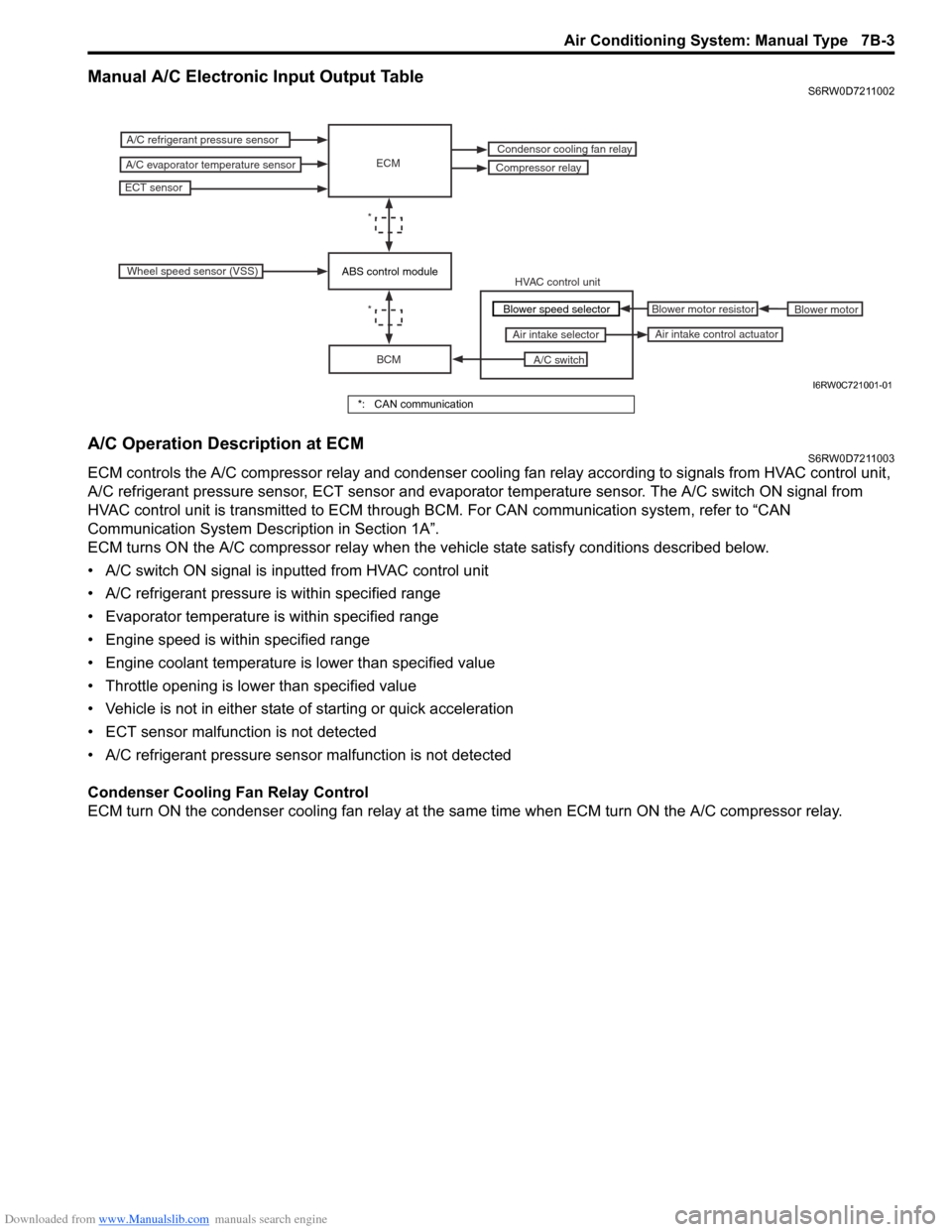
Manual A/C Electronic Input Output TableS6RW0D7211002
A/C Operation Description at ECMS6RW0D7211003
ECM controls the A/C compressor relay and condenser cooling fan relay according to signals from HVAC control unit,
A/C refrigerant pressure sensor, ECT sensor and evaporator temperature sensor. The A/C switch ON signal from
HVAC control unit is transmitted to ECM through BCM. For CAN communication system, refer to “CAN
Communication System Description in Section 1A”.
ECM turns ON the A/C compressor relay when the vehicle state satisfy conditions described below.
• A/C switch ON signal is inputted from HVAC control unit
• A/C refrigerant pressure is within specified range
• Evaporator temperature is within specified range
• Engine speed is within specified range
• Engine coolant temperature is lower than specified value
• Throttle opening is lower than specified value
• Vehicle is not in either state of starting or quick acceleration
• ECT sensor malfunction is not detected
• A/C refrigerant pressure sensor malfunction is not detected
Condenser Cooling Fan Relay Control
ECM turn ON the condenser cooling fan relay at the same time when ECM turn ON the A/C compressor relay.
ECM
BCM
A/C switch Air intake selector
A/C refrigerant pressure sensor
A/C evaporator temperature sensorCompressor relay
ECT sensor
Condensor cooling fan relay
*
Wheel speed sensor (VSS)
HVAC control unit
Blower motor Blower motor resistor
Air intake control actuator
*Blower speed selector
ABS control module
I6RW0C721001-01
*: CAN communication
Page 979 of 1556
Downloaded from www.Manualslib.com manuals search engine Air Conditioning System: Automatic Type 7B-39
General Description
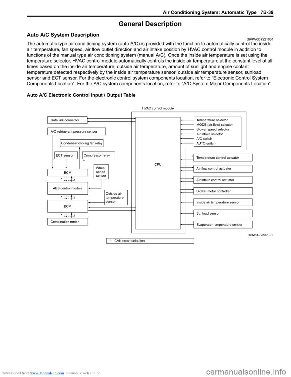
Auto A/C System DescriptionS6RW0D7221001
The automatic type air conditioning system (auto A/C) is provided with the function to automatically control the inside
air temperature, fan speed, air flow outlet direction and air intake position by HVAC control module in addition to
functions of the manual type air conditioning system (manual A/C). Once the inside air temperature is set using the
temperature selector, HVAC control module automatically controls the inside air temperature at the constant level at all
times based on the inside air temperature, outside air temperature, amount of sunlight and engine coolant
temperature detected respectively by the inside air temperature sensor, outside air temperature sensor, sunload
sensor and ECT sensor. For the electronic control system components location, refer to “Electronic Control System
Components Location”. For the A/C system components location, refer to “A/C System Major Components Location”.
Auto A/C Electronic Control Input / Output Table
Temperature selector
MODE (air flow) selector
Blower speed selector
Air intake selector
AUTO switch A/C switch
Outside air
temperature
sensor
A/C refrigerant pressure sensor
Compressor relay
Blower motor controller
Temperature control actuator
Air flow control actuator
Air intake control actuator
BCM
ECM
Data link connector
HVAC control module
CPU
ECT sensor
Sunload sensor
Inside air temperature sensor
Evaporator temperature sensor
Condenser cooling fan relay
Wheel
speed
sensor
*
*
*
Combination meterABS control module
I6RW0C722001-01
*: CAN communication