Shift switch SUZUKI SX4 2006 1.G Service Owner's Guide
[x] Cancel search | Manufacturer: SUZUKI, Model Year: 2006, Model line: SX4, Model: SUZUKI SX4 2006 1.GPages: 1556, PDF Size: 37.31 MB
Page 678 of 1556
Downloaded from www.Manualslib.com manuals search engine 5A-30 Automatic Transmission/Transaxle:
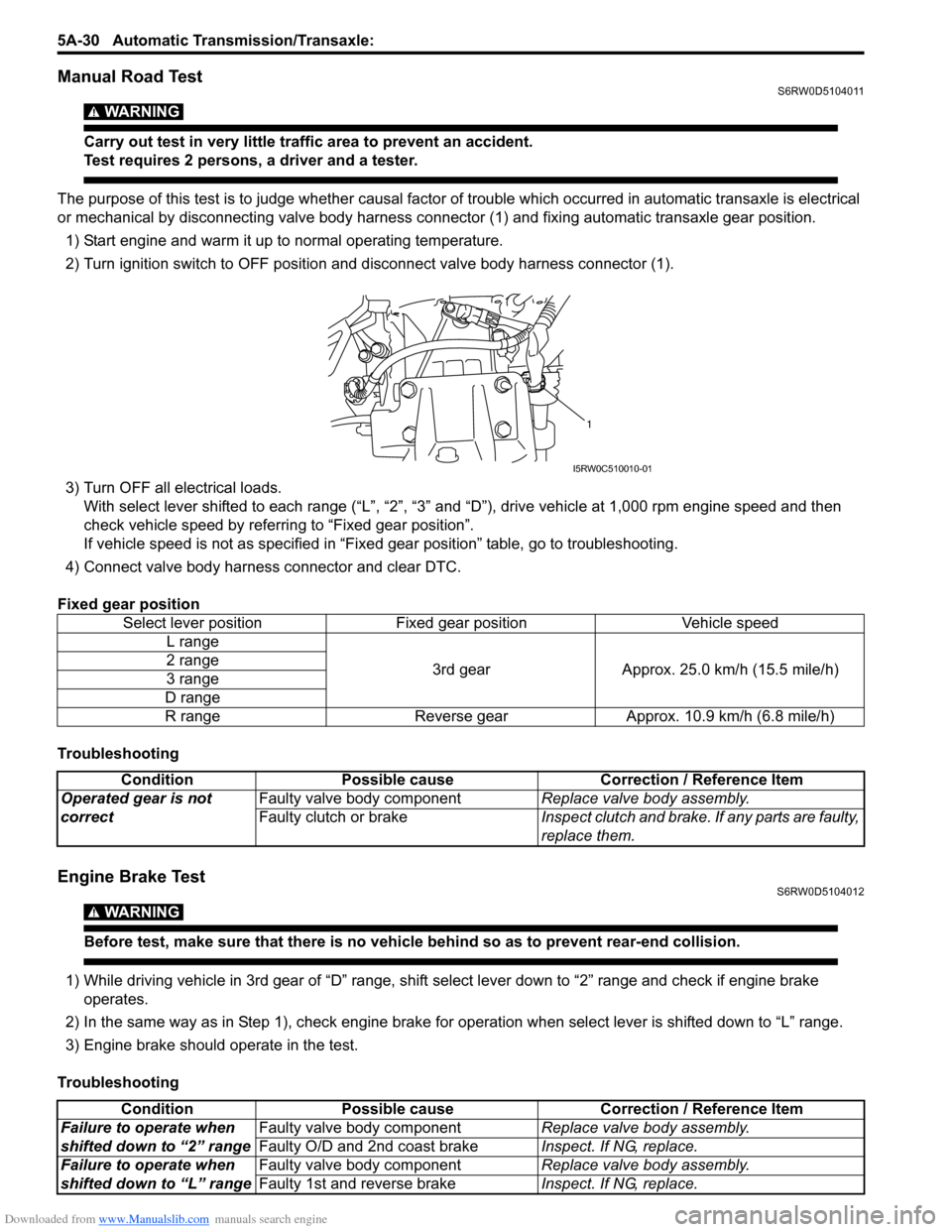
Manual Road TestS6RW0D5104011
WARNING!
Carry out test in very little traffic area to prevent an accident.
Test requires 2 persons, a driver and a tester.
The purpose of this test is to judge whether causal factor of trouble which occurred in automatic transaxle is electrical
or mechanical by disconnecting valve body harness connector (1) and fixing automatic transaxle gear position.
1) Start engine and warm it up to normal operating temperature.
2) Turn ignition switch to OFF position and disconnect valve body harness connector (1).
3) Turn OFF all electrical loads.
With select lever shifted to each range (“L”, “2”, “3” and “D”), drive vehicle at 1,000 rpm engine speed and then
check vehicle speed by referring to “Fixed gear position”.
If vehicle speed is not as specified in “Fixed gear position” table, go to troubleshooting.
4) Connect valve body harness connector and clear DTC.
Fixed gear position
Troubleshooting
Engine Brake TestS6RW0D5104012
WARNING!
Before test, make sure that there is no vehicle behind so as to prevent rear-end collision.
1) While driving vehicle in 3rd gear of “D” range, shift select lever down to “2” range and check if engine brake
operates.
2) In the same way as in Step 1), check engine brake for operation when select lever is shifted down to “L” range.
3) Engine brake should operate in the test.
TroubleshootingSelect lever position Fixed gear position Vehicle speed
L range
3rd gear Approx. 25.0 km/h (15.5 mile/h) 2 range
3 range
D range
R range Reverse gear Approx. 10.9 km/h (6.8 mile/h)
1
I5RW0C510010-01
Condition Possible cause Correction / Reference Item
Operated gear is not
correctFaulty valve body componentReplace valve body assembly.
Faulty clutch or brakeInspect clutch and brake. If any parts are faulty,
replace them.
Condition Possible cause Correction / Reference Item
Failure to operate when
shifted down to “2” rangeFaulty valve body componentReplace valve body assembly.
Faulty O/D and 2nd coast brakeInspect. If NG, replace.
Failure to operate when
shifted down to “L” rangeFaulty valve body componentReplace valve body assembly.
Faulty 1st and reverse brakeInspect. If NG, replace.
Page 680 of 1556
Downloaded from www.Manualslib.com manuals search engine 5A-32 Automatic Transmission/Transaxle:
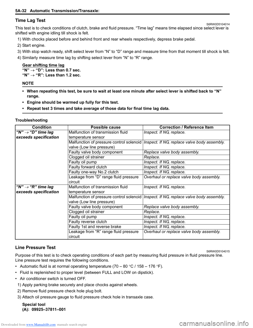
Time Lag TestS6RW0D5104014
This test is to check conditions of clutch, brake and fluid pressure. “Time lag” means time elapsed since select lever is
shifted with engine idling till shock is felt.
1) With chocks placed before and behind front and rear wheels respectively, depress brake pedal.
2) Start engine.
3) With stop watch ready, shift select lever from “N” to “D” range and measure time from that moment till shock is felt.
4) Similarly measure time lag by shifting select lever from “N” to “R” range.
Gear shifting time lag
“N” → “D”: Less than 0.7 sec.
“N” → “R”: Less than 1.2 sec.
NOTE
• When repeating this test, be sure to wait at least one minute after select lever is shifted back to “N”
range.
• Engine should be warmed up fully for this test.
• Repeat test 3 times and take average of those data for final time lag data.
Troubleshooting
Line Pressure TestS6RW0D5104015
Purpose of this test is to check operating conditions of each part by measuring fluid pressure in fluid pressure line.
Line pressure test requires the following conditions.
• Automatic fluid is at normal operating temperature (70 – 80 °C / 158 – 176 °F).
• Fluid is replenished to proper level (between FULL and LOW on dipstick).
• Air conditioner switch is turned OFF.
1) Apply parking brake securely and place chocks against wheels.
2) Remove fluid pressure check hole plug bolt.
3) Attach oil pressure gauge to fluid pressure check hole in transaxle case.
Special tool
(A): 09925–37811–001Condition Possible cause Correction / Reference Item
“N”
→ “D” time lag
exceeds specificationMalfunction of transmission fluid
temperature sensorInspect. If NG, replace.
Malfunction of pressure control solenoid
valve (Low line pressure)Inspect. If NG, replace valve body assembly.
Faulty valve body componentReplace valve body assembly.
Clogged oil strainerReplace.
Faulty oil pumpInspect. If NG, replace.
Faulty forward clutchInspect. If NG, replace.
Faulty one-way No.2 clutchInspect. If NG, replace.
Leakage from “D” range fluid pressure
circuitOverhaul or replace valve body assembly.
“N”
→ “R” time lag
exceeds specificationMalfunction of transmission fluid
temperature sensorInspect. If NG, replace.
Malfunction of pressure control solenoid
valve (Low line pressure)Inspect. If NG, replace valve body assembly.
Faulty valve body componentReplace valve body assembly.
Clogged oil strainerReplace.
Faulty oil pumpInspect. If NG, replace.
Faulty reverse clutchInspect. If NG, replace.
Faulty 1st and reverse brakeInspect. If NG, replace.
Leakage from “R” range fluid pressure
circuitOverhaul or replace valve body assembly.
Page 683 of 1556
Downloaded from www.Manualslib.com manuals search engine Automatic Transmission/Transaxle: 5A-35
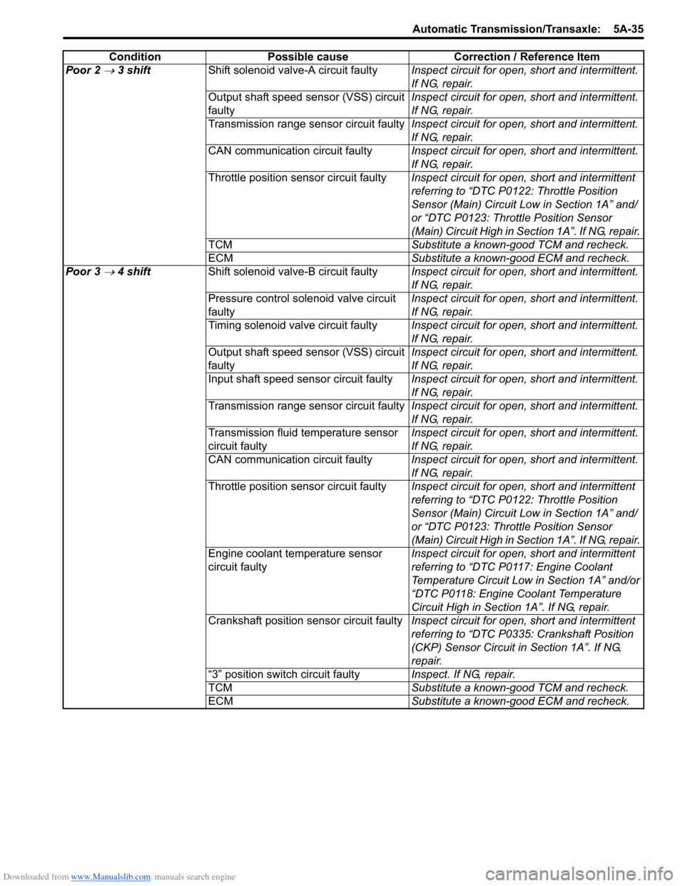
Poor 2 → 3 shiftShift solenoid valve-A circuit faultyInspect circuit for open, short and intermittent.
If NG, repair.
Output shaft speed sensor (VSS) circuit
faulty Inspect circuit for open, short and intermittent.
If NG, repair.
Transmission range sensor circuit faultyInspect circuit for open, short and intermittent.
If NG, repair.
CAN communication circuit faultyInspect circuit for open, short and intermittent.
If NG, repair.
Throttle position sensor circuit faultyInspect circuit for open, short and intermittent
referring to “DTC P0122: Throttle Position
Sensor (Main) Circuit Low in Section 1A” and/
or “DTC P0123: Throttle Position Sensor
(Main) Circuit High in Section 1A”. If NG, repair.
TCMSubstitute a known-good TCM and recheck.
ECMSubstitute a known-good ECM and recheck.
Poor 3
→ 4 shiftShift solenoid valve-B circuit faultyInspect circuit for open, short and intermittent.
If NG, repair.
Pressure control solenoid valve circuit
faultyInspect circuit for open, short and intermittent.
If NG, repair.
Timing solenoid valve circuit faultyInspect circuit for open, short and intermittent.
If NG, repair.
Output shaft speed sensor (VSS) circuit
faulty Inspect circuit for open, short and intermittent.
If NG, repair.
Input shaft speed sensor circuit faulty Inspect circuit for open, short and intermittent.
If NG, repair.
Transmission range sensor circuit faultyInspect circuit for open, short and intermittent.
If NG, repair.
Transmission fluid temperature sensor
circuit faultyInspect circuit for open, short and intermittent.
If NG, repair.
CAN communication circuit faultyInspect circuit for open, short and intermittent.
If NG, repair.
Throttle position sensor circuit faultyInspect circuit for open, short and intermittent
referring to “DTC P0122: Throttle Position
Sensor (Main) Circuit Low in Section 1A” and/
or “DTC P0123: Throttle Position Sensor
(Main) Circuit High in Section 1A”. If NG, repair.
Engine coolant temperature sensor
circuit faultyInspect circuit for open, short and intermittent
referring to “DTC P0117: Engine Coolant
Temperature Circuit Low in Section 1A” and/or
“DTC P0118: Engine Coolant Temperature
Circuit High in Section 1A”. If NG, repair.
Crankshaft position sensor circuit faultyInspect circuit for open, short and intermittent
referring to “DTC P0335: Crankshaft Position
(CKP) Sensor Circuit in Section 1A”. If NG,
repair.
“3” position switch circuit faultyInspect. If NG, repair.
TCMSubstitute a known-good TCM and recheck.
ECMSubstitute a known-good ECM and recheck. Condition Possible cause Correction / Reference Item
Page 684 of 1556
Downloaded from www.Manualslib.com manuals search engine 5A-36 Automatic Transmission/Transaxle:
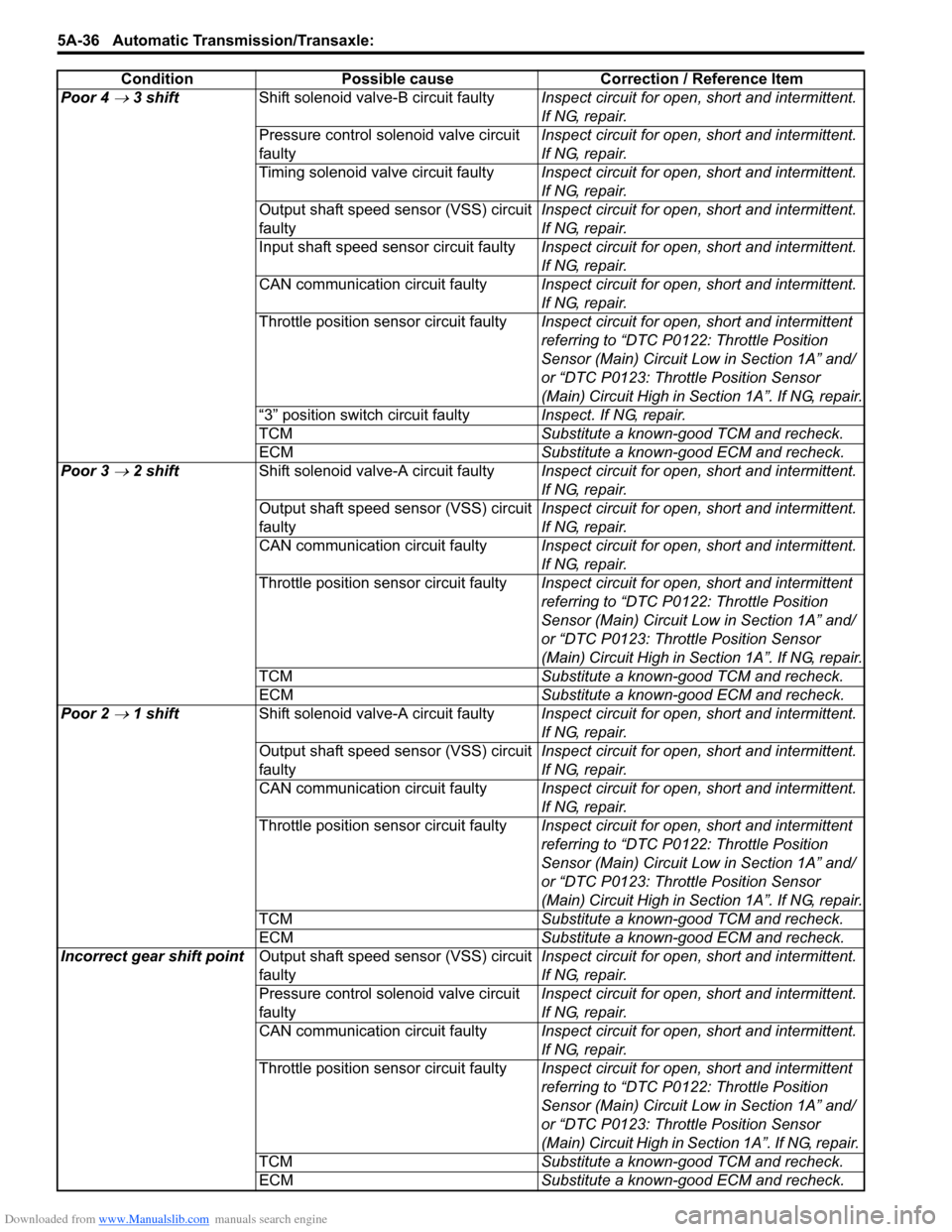
Poor 4 → 3 shiftShift solenoid valve-B circuit faultyInspect circuit for open, short and intermittent.
If NG, repair.
Pressure control solenoid valve circuit
faultyInspect circuit for open, short and intermittent.
If NG, repair.
Timing solenoid valve circuit faultyInspect circuit for open, short and intermittent.
If NG, repair.
Output shaft speed sensor (VSS) circuit
faulty Inspect circuit for open, short and intermittent.
If NG, repair.
Input shaft speed sensor circuit faulty Inspect circuit for open, short and intermittent.
If NG, repair.
CAN communication circuit faultyInspect circuit for open, short and intermittent.
If NG, repair.
Throttle position sensor circuit faultyInspect circuit for open, short and intermittent
referring to “DTC P0122: Throttle Position
Sensor (Main) Circuit Low in Section 1A” and/
or “DTC P0123: Throttle Position Sensor
(Main) Circuit High in Section 1A”. If NG, repair.
“3” position switch circuit faultyInspect. If NG, repair.
TCMSubstitute a known-good TCM and recheck.
ECMSubstitute a known-good ECM and recheck.
Poor 3
→ 2 shiftShift solenoid valve-A circuit faultyInspect circuit for open, short and intermittent.
If NG, repair.
Output shaft speed sensor (VSS) circuit
faulty Inspect circuit for open, short and intermittent.
If NG, repair.
CAN communication circuit faultyInspect circuit for open, short and intermittent.
If NG, repair.
Throttle position sensor circuit faultyInspect circuit for open, short and intermittent
referring to “DTC P0122: Throttle Position
Sensor (Main) Circuit Low in Section 1A” and/
or “DTC P0123: Throttle Position Sensor
(Main) Circuit High in Section 1A”. If NG, repair.
TCMSubstitute a known-good TCM and recheck.
ECMSubstitute a known-good ECM and recheck.
Poor 2
→ 1 shiftShift solenoid valve-A circuit faultyInspect circuit for open, short and intermittent.
If NG, repair.
Output shaft speed sensor (VSS) circuit
faulty Inspect circuit for open, short and intermittent.
If NG, repair.
CAN communication circuit faultyInspect circuit for open, short and intermittent.
If NG, repair.
Throttle position sensor circuit faultyInspect circuit for open, short and intermittent
referring to “DTC P0122: Throttle Position
Sensor (Main) Circuit Low in Section 1A” and/
or “DTC P0123: Throttle Position Sensor
(Main) Circuit High in Section 1A”. If NG, repair.
TCMSubstitute a known-good TCM and recheck.
ECMSubstitute a known-good ECM and recheck.
Incorrect gear shift pointOutput shaft speed sensor (VSS) circuit
faulty Inspect circuit for open, short and intermittent.
If NG, repair.
Pressure control solenoid valve circuit
faultyInspect circuit for open, short and intermittent.
If NG, repair.
CAN communication circuit faultyInspect circuit for open, short and intermittent.
If NG, repair.
Throttle position sensor circuit faultyInspect circuit for open, short and intermittent
referring to “DTC P0122: Throttle Position
Sensor (Main) Circuit Low in Section 1A” and/
or “DTC P0123: Throttle Position Sensor
(Main) Circuit High in Section 1A”. If NG, repair.
TCMSubstitute a known-good TCM and recheck.
ECMSubstitute a known-good ECM and recheck. Condition Possible cause Correction / Reference Item
Page 685 of 1556
Downloaded from www.Manualslib.com manuals search engine Automatic Transmission/Transaxle: 5A-37
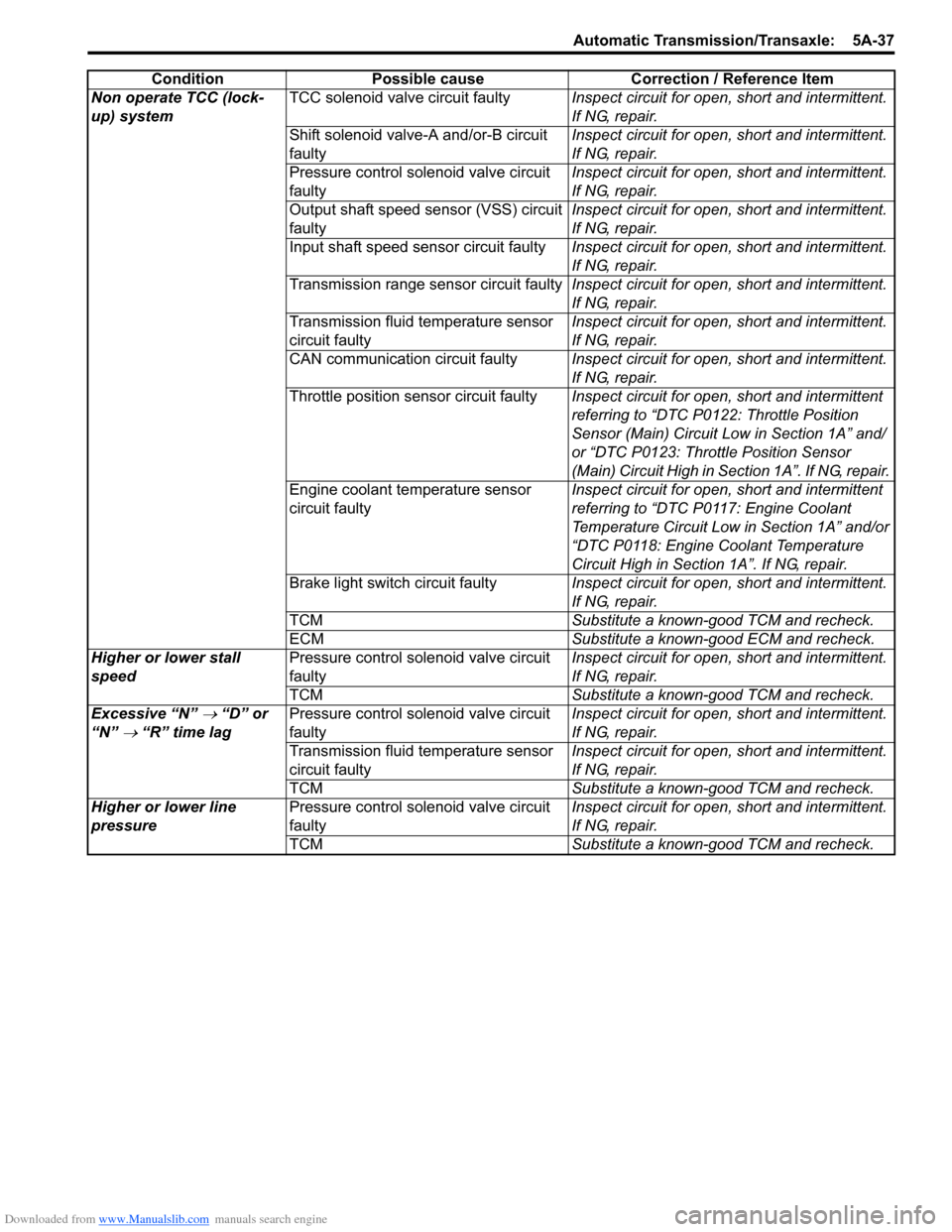
Non operate TCC (lock-
up) systemTCC solenoid valve circuit faultyInspect circuit for open, short and intermittent.
If NG, repair.
Shift solenoid valve-A and/or-B circuit
faultyInspect circuit for open, short and intermittent.
If NG, repair.
Pressure control solenoid valve circuit
faultyInspect circuit for open, short and intermittent.
If NG, repair.
Output shaft speed sensor (VSS) circuit
faulty Inspect circuit for open, short and intermittent.
If NG, repair.
Input shaft speed sensor circuit faulty Inspect circuit for open, short and intermittent.
If NG, repair.
Transmission range sensor circuit faultyInspect circuit for open, short and intermittent.
If NG, repair.
Transmission fluid temperature sensor
circuit faultyInspect circuit for open, short and intermittent.
If NG, repair.
CAN communication circuit faultyInspect circuit for open, short and intermittent.
If NG, repair.
Throttle position sensor circuit faultyInspect circuit for open, short and intermittent
referring to “DTC P0122: Throttle Position
Sensor (Main) Circuit Low in Section 1A” and/
or “DTC P0123: Throttle Position Sensor
(Main) Circuit High in Section 1A”. If NG, repair.
Engine coolant temperature sensor
circuit faultyInspect circuit for open, short and intermittent
referring to “DTC P0117: Engine Coolant
Temperature Circuit Low in Section 1A” and/or
“DTC P0118: Engine Coolant Temperature
Circuit High in Section 1A”. If NG, repair.
Brake light switch circuit faultyInspect circuit for open, short and intermittent.
If NG, repair.
TCMSubstitute a known-good TCM and recheck.
ECMSubstitute a known-good ECM and recheck.
Higher or lower stall
speedPressure control solenoid valve circuit
faultyInspect circuit for open, short and intermittent.
If NG, repair.
TCMSubstitute a known-good TCM and recheck.
Excessive “N”
→ “D” or
“N”
→ “R” time lagPressure control solenoid valve circuit
faultyInspect circuit for open, short and intermittent.
If NG, repair.
Transmission fluid temperature sensor
circuit faultyInspect circuit for open, short and intermittent.
If NG, repair.
TCMSubstitute a known-good TCM and recheck.
Higher or lower line
pressurePressure control solenoid valve circuit
faultyInspect circuit for open, short and intermittent.
If NG, repair.
TCMSubstitute a known-good TCM and recheck. Condition Possible cause Correction / Reference Item
Page 686 of 1556
Downloaded from www.Manualslib.com manuals search engine 5A-38 Automatic Transmission/Transaxle:
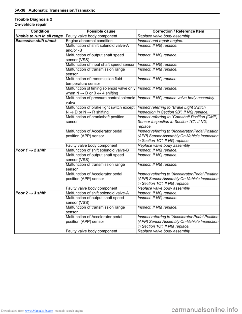
Trouble Diagnosis 2
On-vehicle repair
Condition Possible cause Correction / Reference Item
Unable to run in all rangeFaulty valve body componentReplace valve body assembly.
Excessive shift shockEngine abnormal conditionInspect and repair engine.
Malfunction of shift solenoid valve-A
and/or -BInspect. If NG, replace.
Malfunction of output shaft speed
sensor (VSS)Inspect. If NG, replace.
Malfunction of input shaft speed sensorInspect. If NG, replace.
Malfunction of transmission range
sensorInspect. If NG, replace.
Malfunction of transmission fluid
temperature sensorInspect. If NG, replace.
Malfunction of timing solenoid valve only
when N → D or 3 ↔ 4 shiftingInspect. If NG, replace.
Malfunction of pressure control solenoid
valveInspect. If NG, replace valve body assembly.
Malfunction of brake light switch except
N → D or N → R shiftingInspect referring to “Brake Light Switch
Inspection in Section 9B”. If NG, replace.
Malfunction of crankshaft position
sensorInspect referring to “Camshaft Position (CMP)
Sensor Inspection in Section 1C”. If NG,
replace.
Malfunction of Accelerator pedal
position (APP) sensorInspect referring to “Accelerator Pedal Position
(APP) Sensor Assembly On-Vehicle Inspection
in Section 1C”. If NG, replace.
Faulty valve body componentReplace valve body assembly.
Poor 1
→ 2 shiftMalfunction of shift solenoid valve-BInspect. If NG, replace.
Malfunction of output shaft speed
sensor (VSS)Inspect. If NG, replace.
Malfunction of transmission range
sensorInspect. If NG, replace.
Malfunction of Accelerator pedal
position (APP) sensorInspect referring to “Accelerator Pedal Position
(APP) Sensor Assembly On-Vehicle Inspection
in Section 1C”. If NG, replace.
Faulty valve body componentReplace valve body assembly.
Poor 2
→ 3 shiftMalfunction of shift solenoid valve-AInspect. If NG, replace.
Malfunction of output shaft speed
sensor (VSS)Inspect. If NG, replace.
Malfunction of transmission range
sensorInspect. If NG, replace.
Malfunction of Accelerator pedal
position (APP) sensorInspect referring to “Accelerator Pedal Position
(APP) Sensor Assembly On-Vehicle Inspection
in Section 1C”. If NG, replace.
Faulty valve body componentReplace valve body assembly.
Page 687 of 1556
Downloaded from www.Manualslib.com manuals search engine Automatic Transmission/Transaxle: 5A-39
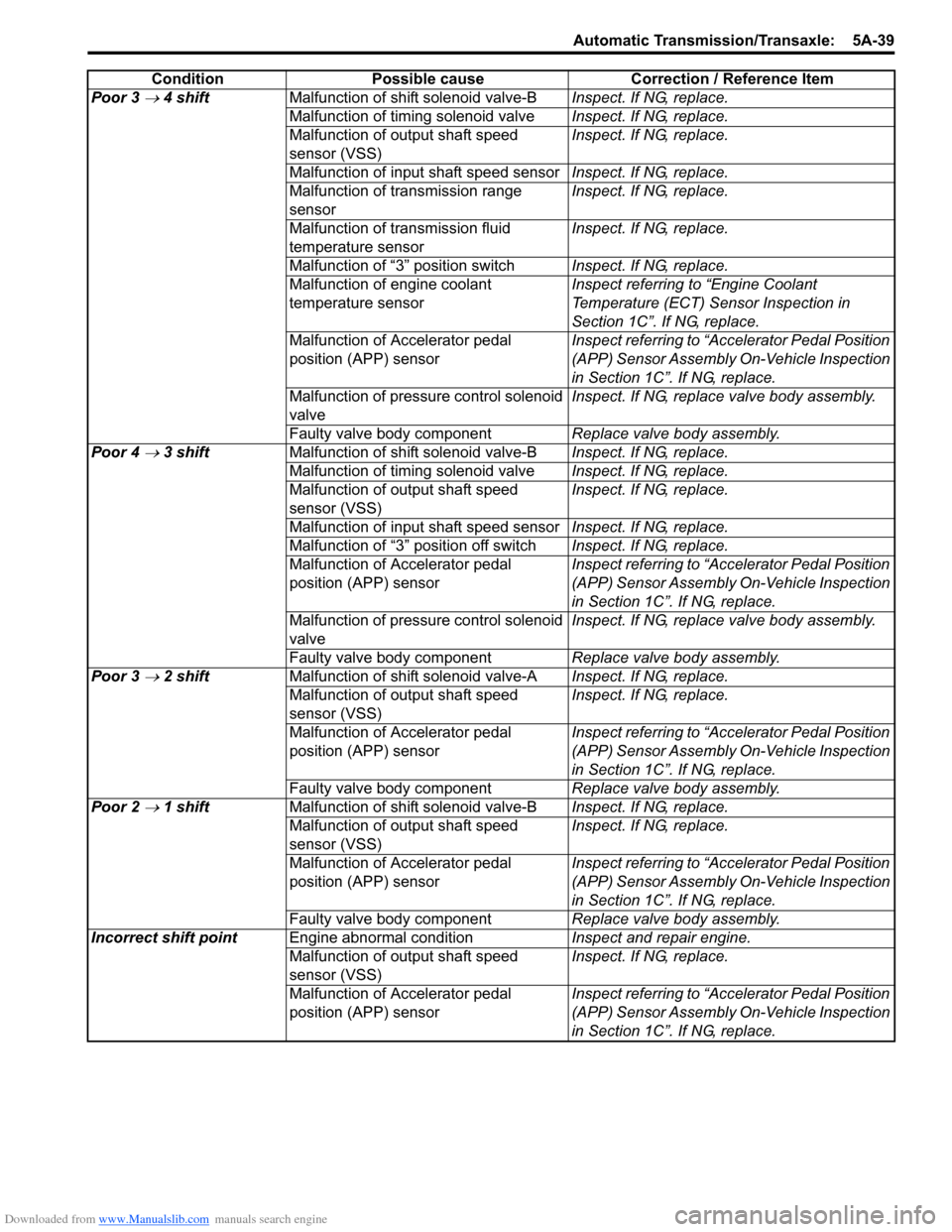
Poor 3 → 4 shiftMalfunction of shift solenoid valve-BInspect. If NG, replace.
Malfunction of timing solenoid valveInspect. If NG, replace.
Malfunction of output shaft speed
sensor (VSS)Inspect. If NG, replace.
Malfunction of input shaft speed sensorInspect. If NG, replace.
Malfunction of transmission range
sensorInspect. If NG, replace.
Malfunction of transmission fluid
temperature sensorInspect. If NG, replace.
Malfunction of “3” position switchInspect. If NG, replace.
Malfunction of engine coolant
temperature sensorInspect referring to “Engine Coolant
Temperature (ECT) Sensor Inspection in
Section 1C”. If NG, replace.
Malfunction of Accelerator pedal
position (APP) sensorInspect referring to “Accelerator Pedal Position
(APP) Sensor Assembly On-Vehicle Inspection
in Section 1C”. If NG, replace.
Malfunction of pressure control solenoid
valveInspect. If NG, replace valve body assembly.
Faulty valve body componentReplace valve body assembly.
Poor 4
→ 3 shiftMalfunction of shift solenoid valve-BInspect. If NG, replace.
Malfunction of timing solenoid valveInspect. If NG, replace.
Malfunction of output shaft speed
sensor (VSS)Inspect. If NG, replace.
Malfunction of input shaft speed sensorInspect. If NG, replace.
Malfunction of “3” position off switchInspect. If NG, replace.
Malfunction of Accelerator pedal
position (APP) sensorInspect referring to “Accelerator Pedal Position
(APP) Sensor Assembly On-Vehicle Inspection
in Section 1C”. If NG, replace.
Malfunction of pressure control solenoid
valveInspect. If NG, replace valve body assembly.
Faulty valve body componentReplace valve body assembly.
Poor 3
→ 2 shiftMalfunction of shift solenoid valve-AInspect. If NG, replace.
Malfunction of output shaft speed
sensor (VSS)Inspect. If NG, replace.
Malfunction of Accelerator pedal
position (APP) sensorInspect referring to “Accelerator Pedal Position
(APP) Sensor Assembly On-Vehicle Inspection
in Section 1C”. If NG, replace.
Faulty valve body componentReplace valve body assembly.
Poor 2
→ 1 shiftMalfunction of shift solenoid valve-BInspect. If NG, replace.
Malfunction of output shaft speed
sensor (VSS)Inspect. If NG, replace.
Malfunction of Accelerator pedal
position (APP) sensorInspect referring to “Accelerator Pedal Position
(APP) Sensor Assembly On-Vehicle Inspection
in Section 1C”. If NG, replace.
Faulty valve body componentReplace valve body assembly.
Incorrect shift pointEngine abnormal conditionInspect and repair engine.
Malfunction of output shaft speed
sensor (VSS)Inspect. If NG, replace.
Malfunction of Accelerator pedal
position (APP) sensorInspect referring to “Accelerator Pedal Position
(APP) Sensor Assembly On-Vehicle Inspection
in Section 1C”. If NG, replace. Condition Possible cause Correction / Reference Item
Page 688 of 1556
Downloaded from www.Manualslib.com manuals search engine 5A-40 Automatic Transmission/Transaxle:
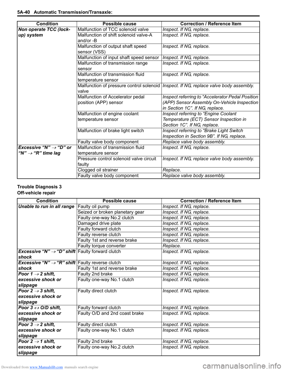
Trouble Diagnosis 3
Off-vehicle repairNon operate TCC (lock-
up) systemMalfunction of TCC solenoid valveInspect. If NG, replace.
Malfunction of shift solenoid valve-A
and/or -BInspect. If NG, replace.
Malfunction of output shaft speed
sensor (VSS)Inspect. If NG, replace.
Malfunction of input shaft speed sensorInspect. If NG, replace.
Malfunction of transmission range
sensorInspect. If NG, replace.
Malfunction of transmission fluid
temperature sensorInspect. If NG, replace.
Malfunction of pressure control solenoid
valveInspect. If NG, replace valve body assembly.
Malfunction of Accelerator pedal
position (APP) sensorInspect referring to “Accelerator Pedal Position
(APP) Sensor Assembly On-Vehicle Inspection
in Section 1C”. If NG, replace.
Malfunction of engine coolant
temperature sensorInspect referring to “Engine Coolant
Temperature (ECT) Sensor Inspection in
Section 1C”. If NG, replace.
Malfunction of brake light switchInspect referring to “Brake Light Switch
Inspection in Section 9B”. If NG, replace.
Faulty valve body componentReplace valve body assembly.
Excessive “N”
→ “D” or
“N”
→ “R” time lagMalfunction of transmission fluid
temperature sensorInspect. If NG, replace.
Pressure control solenoid valve circuit
faultyInspect. If NG, replace valve body assembly.
Clogged oil strainerReplace.
Faulty valve body componentReplace valve body assembly. Condition Possible cause Correction / Reference Item
Condition Possible cause Correction / Reference Item
Unable to run in all rangeFaulty oil pumpInspect. If NG, replace.
Seized or broken planetary gearInspect. If NG, replace.
Faulty one-way No.2 clutchInspect. If NG, replace.
Damaged drive plateInspect. If NG, replace.
Faulty forward clutchInspect. If NG, replace.
Faulty reverse clutchInspect. If NG, replace.
Faulty 1st and reverse brakeInspect. If NG, replace.
Faulty torque converterReplace.
Excessive “N”
→ “D” shift
shockFaulty forward clutchInspect. If NG, replace.
Excessive “N”
→ “R” shift
shockFaulty reverse clutchInspect. If NG, replace.
Faulty 1st and reverse brakeInspect. If NG, replace.
Poor 1
→ 2 shift,
excessive shock or
slippageFaulty 2nd brakeInspect. If NG, replace.
Faulty one-way No.1 clutchInspect. If NG, replace.
Poor 2
→ 3 shift,
excessive shock or
slippageFaulty direct clutchInspect. If NG, replace.
Poor 3
↔ O/D shift,
excessive shock or
slippageFaulty forward clutchInspect. If NG, replace.
Faulty O/D and 2nd coast brakeInspect. If NG, replace.
Poor 3
→ 2 shift,
excessive shock or
slippageFaulty direct clutchInspect. If NG, replace.
Faulty one-way No.1 clutchInspect. If NG, replace.
Poor 2
→ 1 shift,
excessive shock or
slippageFaulty 2nd brakeInspect. If NG, replace.
Faulty one-way No.2 clutchInspect. If NG, replace.
Page 689 of 1556
Downloaded from www.Manualslib.com manuals search engine Automatic Transmission/Transaxle: 5A-41
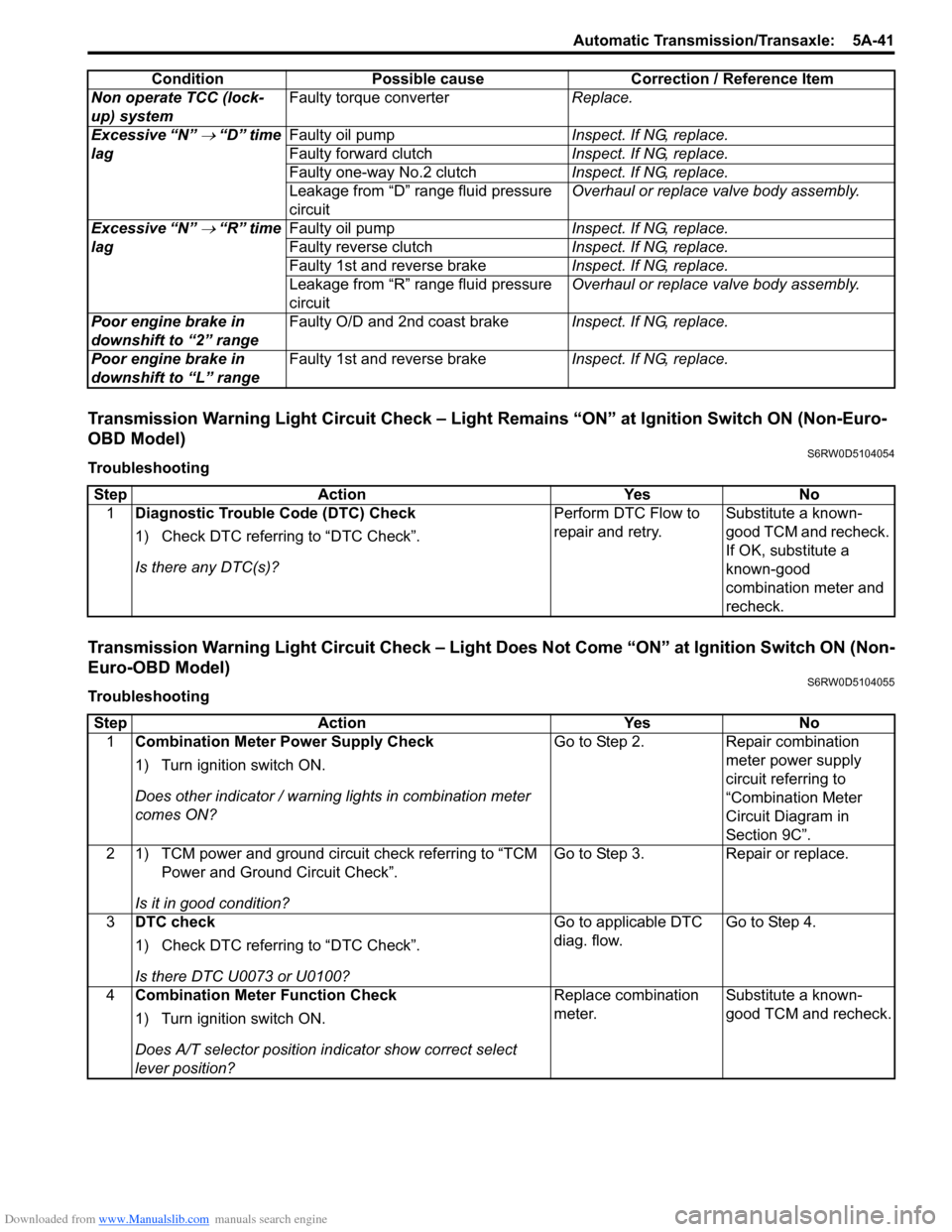
Transmission Warning Light Circuit Check – Light Remains “ON” at Ignition Switch ON (Non-Euro-
OBD Model)
S6RW0D5104054
Troubleshooting
Transmission Warning Light Circuit Check – Light Does Not Come “ON” at Ignition Switch ON (Non-
Euro-OBD Model)
S6RW0D5104055
TroubleshootingNon operate TCC (lock-
up) systemFaulty torque converterReplace.
Excessive “N”
→ “D” time
lagFaulty oil pumpInspect. If NG, replace.
Faulty forward clutchInspect. If NG, replace.
Faulty one-way No.2 clutchInspect. If NG, replace.
Leakage from “D” range fluid pressure
circuitOverhaul or replace valve body assembly.
Excessive “N”
→ “R” time
lagFaulty oil pumpInspect. If NG, replace.
Faulty reverse clutchInspect. If NG, replace.
Faulty 1st and reverse brakeInspect. If NG, replace.
Leakage from “R” range fluid pressure
circuitOverhaul or replace valve body assembly.
Poor engine brake in
downshift to “2” rangeFaulty O/D and 2nd coast brakeInspect. If NG, replace.
Poor engine brake in
downshift to “L” rangeFaulty 1st and reverse brakeInspect. If NG, replace. Condition Possible cause Correction / Reference Item
Step Action Yes No
1Diagnostic Trouble Code (DTC) Check
1) Check DTC referring to “DTC Check”.
Is there any DTC(s)?Perform DTC Flow to
repair and retry.Substitute a known-
good TCM and recheck.
If OK, substitute a
known-good
combination meter and
recheck.
Step Action Yes No
1Combination Meter Power Supply Check
1) Turn ignition switch ON.
Does other indicator / warning lights in combination meter
comes ON?Go to Step 2. Repair combination
meter power supply
circuit referring to
“Combination Meter
Circuit Diagram in
Section 9C”.
2 1) TCM power and ground circuit check referring to “TCM
Power and Ground Circuit Check”.
Is it in good condition?Go to Step 3. Repair or replace.
3DTC check
1) Check DTC referring to “DTC Check”.
Is there DTC U0073 or U0100?Go to applicable DTC
diag. flow.Go to Step 4.
4Combination Meter Function Check
1) Turn ignition switch ON.
Does A/T selector position indicator show correct select
lever position?Replace combination
meter.Substitute a known-
good TCM and recheck.
Page 691 of 1556

Downloaded from www.Manualslib.com manuals search engine Automatic Transmission/Transaxle: 5A-43
DTC Detecting Condition and Trouble Area
DTC Confirmation Procedure
1) Connect scan tool to DLC with ignition switch OFF.
2) Clear DTCs in TCM memory by using scan tool.
3) Start engine and shift select lever to “D” range.
4) Keep engine running at idle speed for 25 seconds or more.
5) Stop vehicle and check DTC.
DTC TroubleshootingDTC detecting condition Trouble area
Multiple or more signals are inputted simultaneously for 10
seconds.• Select cable maladjusted
• Transmission range sensor maladjusted
• Transmission range sensor or its circuit malfunction
•TCM
Step Action Yes No
1Was “A/T System Check” performed?Go to Step 2. Go to “A/T System
Check”.
2Do you have SUZUKI scan tool?Go to Step 3. Go to Step 4.
3Check transmission range sensor circuit for operation
Check by using SUZUKI scan tool:
1) Connect SUZUKI scan tool to DLC with ignition switch
OFF.
2) Turn ignition switch ON and check transmission range
signal (“P”, “R”, “N”, “D”, “2” or “L”) on display when
shifting select lever to each range.
Is applicable range indicated?Intermittent trouble.
Check for intermittent
referring to “Intermittent
and Poor Connection
Inspection in Section
00”.Go to Step 5.
4Check transmission range sensor circuit for operation
Check by not using SUZUKI scan tool:
1) Turn ignition switch ON.
2) Check voltage at terminals “C07-1”, “C07-7”, “C07-8”,
“C07-18”, “C07-19” and “C07-20” respectively with
select lever shifted to each range.
Taking terminal “C07-19” as an example, is battery
voltage indicated only when select lever is shifted to “2”
range and 0 V for other ranges as shown in the following
table.
Check voltage at other terminals likewise, referring to the
following table.
Are check results satisfactory?Intermittent trouble.
Check for intermittent
referring to “Intermittent
and Poor Connection
Inspection in Section
00”.Go to Step 5.
5 1) Check select cable for adjustment referring to “Select
Cable Adjustment”.
Is it adjusted correctly?Go to Step 6. Adjust.
6Check transmission range sensor for installation
position
1) Shift select lever to “N” range.
2) Check that “N” reference line on sensor and needle
direction shaped on lock washer are aligned.
Are they aligned?Go to Step 7. Adjust.