content SUZUKI SX4 2006 1.G Service Owner's Guide
[x] Cancel search | Manufacturer: SUZUKI, Model Year: 2006, Model line: SX4, Model: SUZUKI SX4 2006 1.GPages: 1556, PDF Size: 37.31 MB
Page 927 of 1556
Downloaded from www.Manualslib.com manuals search engine Table of Contents 7-iii
Condenser Assembly Removal and
Installation ....................................................... 7B-87
Evaporator Inspection ....................................... 7B-87
Evaporator Temperature Sensor Removal
and Installation ................................................ 7B-87
Evaporator Temperature Sensor Inspection ..... 7B-87
Expansion Valve Removal and Installation ....... 7B-87
Expansion Valve Inspection .............................. 7B-87
A/C Refrigerant Pressure Sensor and Its
Circuit Inspection ............................................ 7B-87
A/C Refrigerant Pressure Sensor Removal
and Installation ................................................ 7B-87
Compressor Relay Inspection ........................... 7B-87
Compressor Drive Belt Inspection and
Adjustment ...................................................... 7B-87Compressor Drive Belt Removal and
Installation ....................................................... 7B-87
Compressor Assembly Removal and
Installation ....................................................... 7B-87
Compressor Assembly Components................. 7B-87
Magnet Clutch Removal and Installation........... 7B-87
Magnet Clutch Inspection.................................. 7B-87
Thermal Switch Inspection ................................ 7B-87
Thermal Switch Removal and Installation ......... 7B-87
Relief Valve Inspection...................................... 7B-87
Special Tools and Equipment ...........................7B-88
Recommended Service Material ....................... 7B-88
Special Tool ...................................................... 7B-88
Page 1029 of 1556
Downloaded from www.Manualslib.com manuals search engine Table of Contents 8- i
8
Section 8
CONTENTS
Restraint
Precautions ................................................. 8-1
Precautions............................................................. 8-1
Precautions on Restraint ....................................... 8-1
Seat Belts ................................................. 8A-1
Precautions........................................................... 8A-1
Precautions on Service and Diagnosis of Seat
Belt .................................................................... 8A-1
General Description ............................................. 8A-2
Seat Belt Construction ........................................ 8A-2
Diagnostic Information and Procedures ............ 8A-3
Repair and Inspection Required after
Accident ............................................................ 8A-3
Repair Instructions .............................................. 8A-4
Front Seat Belt Components ............................... 8A-4
Front Seat Belt Removal and Installation ............ 8A-5
Front Seat Belt Inspection................................... 8A-6
Rear Seat Belt Components ............................... 8A-7
Rear Seat Belt Removal and Installation ............ 8A-8
Rear Seat Belt Inspection ................................... 8A-8
Specifications....................................................... 8A-8
Tightening Torque Specifications ........................ 8A-8
Air Bag System ........................................ 8B-1
Precautions........................................................... 8B-1
Precautions on Service and Diagnosis of Air
Bag System....................................................... 8B-1
Precautions on Handling and Storage of Air
Bag System Components ................................. 8B-1
Precautions on Disposal of Air Bag and Seat
Belt Pretensioner .............................................. 8B-5
General Description ............................................. 8B-5
Air Bag System Construction .............................. 8B-5
Air Bag System Block Diagram ........................... 8B-6
Air Bag System Input / Output Table .................. 8B-7
Schematic and Routing Diagram ........................ 8B-8
Air Bag System Wiring Circuit Diagram .............. 8B-8
Component Location ......................................... 8B-11
Air Bag System Components, Wiring and
Connectors Location ....................................... 8B-11
Diagnostic Information and Procedures .......... 8B-12
Air Bag Diagnostic System Check .................... 8B-12
Air Bag Diagnostic System Check Flow ............ 8B-13
DTC Table ......................................................... 8B-14DTC Check........................................................ 8B-18
DTC Clearance ................................................. 8B-18
Scan Tool Data ................................................. 8B-18
“AIR BAG” Warning Light Comes ON Steady ... 8B-19
“AIR BAG” Warning Light Does Not Come ON .. 8B-22
Serial Data Link Circuit Check .......................... 8B-23
DTC B1013: SDM Internal Failure .................... 8B-25
DTC B1014: “AIR BAG” Warning Light Circuit .. 8B-26
DTC B1016: Power Supply Voltage too High.... 8B-26
DTC B1017: Power Supply Voltage too Low .... 8B-27
DTC B1021: Front Air Bag Deployment
Record............................................................. 8B-28
DTC B1024 / B1025: Side Air-Bag
Deployment Record ........................................ 8B-29
DTC B1026: Seat Belt Pretensioner
Activation Record ............................................ 8B-29
DTC B1027: Number of Deployment Times
Exceeded Limit................................................ 8B-30
DTC B1031: Driver Air Bag Circuit High
Resistance ...................................................... 8B-31
DTC B1032: Driver Air Bag Circuit Low
Resistance ...................................................... 8B-33
DTC B1033: Driver Air Bag Circuit Shorted to
Ground ............................................................ 8B-35
DTC B1034: Driver Air Bag Circuit Shorted to
Power Supply .................................................. 8B-37
DTC B1041: Passenger Air Bag Circuit High
Resistance ...................................................... 8B-40
DTC B1042: Passenger Air Bag Circuit Low
Resistance ...................................................... 8B-43
DTC B1043: Passenger Air Bag Circuit
Shorted to Ground........................................... 8B-45
DTC B1044: Passenger Air Bag Circuit
Shorted to Power Supply ................................ 8B-46
DTC B1051 / B1055: Seat Belt Pretensioner
Circuit High Resistance ................................... 8B-48
DTC B1052 / B1056: Seat Belt Pretensioner
Circuit Low Resistance.................................... 8B-51
DTC B1053 / B1057: Seat Belt Pretensioner
Shorted to Ground........................................... 8B-52
DTC B1054 / B1058: Seat Belt Pretensioner
Circuit Shorted to Power Supply ..................... 8B-54
DTC B1061 / B1065: Side-Air Bag Circuit
High Resistance .............................................. 8B-55
Page 1030 of 1556
Downloaded from www.Manualslib.com manuals search engine 8-ii Table of Contents
DTC B1062 / B1066: Side-Air Bag Circuit Low
Resistance ...................................................... 8B-59
DTC B1063 / B1067: Side-Air Bag Circuit
Shorted to Ground .......................................... 8B-61
DTC B1064 / B1068: Side-Air Bag Circuit
Shorted to Power Supply ................................ 8B-64
DTC B1071: Driver Forward Impact-Sensor
Communication Data Inconsistent .................. 8B-66
DTC B1072: Driver Forward Impact-Sensor
Communication Data Invalid ........................... 8B-66
DTC B1073: Driver Forward Impact-Sensor
Circuit Shorted to Ground ............................... 8B-67
DTC B1074: Driver Forward Impact-Sensor
Circuit Open .................................................... 8B-68
DTC B1081 / B1091: Side Impact-Sensor No
Response ........................................................ 8B-70
DTC B1082 / B1092: Side Impact-Sensor
Communication DATA Invalid ......................... 8B-70
DTC B1083 / B1093: Side Impact-Sensor
Circuit Shorted to Ground ............................... 8B-71
DTC B1084 / B1094: Side Impact-Sensor
Circuit Open .................................................... 8B-73
DTC B1085 / B1095: Side Impact-Sensor
Communication DATA Inconsistent ................ 8B-74
DTC B1361 / B1365: Curtain-Air Bag Circuit
High Resistance .............................................. 8B-75
DTC B1362 / B1366: Curtain-Air Bag Circuit
Low Resistance ............................................... 8B-79
DTC B1363 / B1367: Curtain-Air Bag Circuit
Shorted to Ground .......................................... 8B-81
DTC B1364 / B1368: Curtain-Air Bag Circuit
Shorted to Power Supply ................................ 8B-83
SDM Power Supply and Ground Circuit
Check .............................................................. 8B-85
Contact Coil Cable and Its Circuit Check .......... 8B-87
Inspection of Intermittent and Poor
Connections .................................................... 8B-89Repair and Inspection Required after
Accident .......................................................... 8B-90
Repair Instructions ............................................8B-93
Disabling Air Bag System.................................. 8B-93
Enabling Air Bag System .................................. 8B-93
SDM Removal and Installation .......................... 8B-94
SDM Inspection ................................................. 8B-95
Driver Air Bag (Inflator) Module Removal and
Installation ....................................................... 8B-95
Driver Air Bag (Inflator) Module Inspection ....... 8B-97
Passenger Air Bag (Inflator) Module Removal
and Installation ................................................ 8B-97
Passenger Air Bag (Inflator) Module
Inspection ........................................................ 8B-99
Side-Air Bag (Inflator) Module Removal and
Installation ....................................................... 8B-99
Side-Air Bag (Inflator) Inspection .................... 8B-101
Side Curtain-Air Bag (Inflator) Module
Removal and Installation ............................... 8B-102
Side Curtain-Air Bag (Inflator) Module
Inspection ...................................................... 8B-103
Forward Impact-Sensor Removal and
Installation ..................................................... 8B-103
Forward Impact-Sensor Inspection ................. 8B-104
Side Impact-Sensor Removal and Installation 8B-105
Side Impact-Sensor Inspection ....................... 8B-105
Passenger Air Bag (Inflator) Module Repair
Harness Installation....................................... 8B-106
Air Bag (Inflator) Module and Seat Belt
Pretensioner Disposal ................................... 8B-107
Deployed Air Bag (Inflator) Module and
Activated Seat Belt Pretensioner Disposal.... 8B-117
Specifications ...................................................8B-118
Tightening Torque Specifications .................... 8B-118
Special Tools and Equipment .........................8B-118
Use of Special Tools ....................................... 8B-118
Special Tool .................................................... 8B-120
Page 1161 of 1556
Downloaded from www.Manualslib.com manuals search engine Table of Contents 9- i
9
Section 9
CONTENTS
Body, Cab and Accessories
Precautions ................................................. 9-1
Precautions............................................................. 9-1
Precautions on Body, Cab and Accessories ......... 9-1
Precautions for Body Service ................................ 9-1
Fastener Caution for Body Service ....................... 9-1
Wiring Systems........................................ 9A-1
Precautions........................................................... 9A-1
Cautions in Body Electrical System Servicing..... 9A-1
General Description ............................................. 9A-1
Abbreviations ...................................................... 9A-1
Wire / Connector Color Symbols ......................... 9A-1
Symbols and Marks ............................................ 9A-2
How to Read Connector Layout Diagram ........... 9A-4
How to Read Connector Codes and Terminal
Nos.................................................................... 9A-5
How to Read Ground Point ................................. 9A-8
How to Read Power Supply Diagram.................. 9A-9
How to Read System Circuit Diagram................. 9A-9
Connector Layout Diagram ............................... 9A-11
Connector Layout Diagram ............................... 9A-11
Engine Compartment ........................................ 9A-11
Instrument Panel ............................................... 9A-19
Door, Roof......................................................... 9A-25
Floor .................................................................. 9A-28
Rear .................................................................. 9A-32
Ground Point ...................................................... 9A-33
Ground (earth) Point ......................................... 9A-33
Power Supply Diagram ...................................... 9A-34
Power Supply Diagram ..................................... 9A-34
Fuses and the Protected Parts ......................... 9A-36
Fuses in Main Fuse Box ................................... 9A-36
Individual Circuit Fuse Box No. 1 ...................... 9A-37
Individual Circuit Fuse Box No. 2 (In J/B
(Except Taiwan)) ............................................. 9A-38
Individual Circuit Fuse Box No. 2 (In J/B
(Taiwan)) ......................................................... 9A-40
Junction Block (J/B) Connector / Fuse Layout .. 9A-42
Junction Block Inner Circuit (Overview
(Except Taiwan)) ............................................. 9A-43
Junction Block Inner Circuit (Detail (Except
Taiwan)) .......................................................... 9A-45
Junction Block Inner Circuit (Overview
(Taiwan)) ......................................................... 9A-50Junction Block Inner Circuit (Detail (Taiwan)) ... 9A-52
System Circuit Diagram.....................................9A-57
System Circuit Diagram .................................... 9A-57
A-1 Cranking System Circuit Diagram .............. 9A-58
A-2 Charging System Circuit Diagram .............. 9A-59
A-3 Ignition System Circuit Diagram (M15A
engine, M16A engine) ..................................... 9A-60
A-3 Ignition System Circuit Diagram (J20A
engine) ............................................................ 9A-61
A-4 Cooling System Circuit Diagram (M15A
engine, M16A engine) ..................................... 9A-62
A-4 Cooling System Circuit Diagram (J20A
engine) ............................................................ 9A-63
A-5 Engine and A/C Control System Circuit
Diagram (M15A engine) .................................. 9A-64
A-5 Engine and A/C Control System Circuit
Diagram (M16A engine) .................................. 9A-68
A-5 Engine and A/C Control System Circuit
Diagram (J20A engine) ................................... 9A-72
A-6 A/T Control System Circuit Diagram........... 9A-76
A-7 Immobilizer System Circuit Diagram .......... 9A-78
A-8 Body Control System Circuit Diagram
(Except Taiwan) .............................................. 9A-79
A-8 Body Control System Circuit Diagram
(Taiwan) .......................................................... 9A-83
A-10 4WD Control System (Except Taiwan) ..... 9A-87
B-1 Windshield Wiper and Washer Circuit
Diagram........................................................... 9A-88
B-2 Rear Wiper and Washer Circuit Diagram
(Except Taiwan) .............................................. 9A-89
B-2 Rear Wiper and Washer Circuit Diagram
(Taiwan) .......................................................... 9A-90
B-3 Rear Defogger Circuit Diagram (Except
Taiwan) ........................................................... 9A-91
B-3 Rear Defogger Circuit Diagram (Taiwan) ... 9A-92
B-4 Power Window Circuit Diagram .................. 9A-93
B-5 Power Door Lock Circuit Diagram (Except
Taiwan) ........................................................... 9A-95
B-5 Power Door Lock Circuit Diagram
(Taiwan) .......................................................... 9A-97
B-6 Power Mirror Circuit Diagram (Except
Taiwan) ........................................................... 9A-99
B-6 Power Mirror Circuit Diagram (Taiwan) .... 9A-100
B-7 Horn Circuit Diagram ................................ 9A-101
B-8 Seat Heater Circuit Diagram..................... 9A-102
Page 1162 of 1556
Downloaded from www.Manualslib.com manuals search engine 9-ii Table of Contents
B-9 Keyless Start System Circuit Diagram...... 9A-103
C-1 Combination Meter Circuit Diagram
(Meter) .......................................................... 9A-104
C-2 Combination Meter Circuit Diagram
(Indicator) ...................................................... 9A-105
C-3 Combination Meter Circuit Diagram
(Warning Light) ............................................. 9A-106
D-1 Headlight System Circuit Diagram
(Except Taiwan) ............................................ 9A-108
D-1 Headlight System Circuit Diagram
(Taiwan) ........................................................ 9A-110
D-2 Position, Tail and Licence Plate Light
System Circuit Diagram (Except Taiwan) ..... 9A-111
D-2 Position, Tail and Licence Plate Light
System Circuit Diagram (Taiwan) ................. 9A-112
D-3 Front Fog Light System Circuit Diagram
(Except Taiwan) ............................................ 9A-113
D-3 Front Fog Light System Circuit Diagram
(Taiwan) ........................................................ 9A-114
D-4 Illumination Light System Circuit Diagram
(Except Taiwan) ............................................ 9A-115
D-4 Illumination Light System Circuit Diagram
(Taiwan) ........................................................ 9A-116
D-5 Interior Light System Circuit Diagram
(Except Taiwan) ............................................ 9A-117
D-5 Interior Light System Circuit Diagram
(Taiwan) ........................................................ 9A-118
D-6 Turn Signal and Hazard Warning Light
System Circuit Diagram (Except Taiwan) ..... 9A-119
D-6 Turn Signal and Hazard Warning Light
System Circuit Diagram (Taiwan) ................. 9A-121
D-7 Brake Light System Circuit Diagram ........ 9A-123
D-8 Back-Up Light System Circuit Diagram .... 9A-124
D-9 Headlight Beam Leveling System Circuit
Diagram (Manual Leveling)........................... 9A-125
D-10 Rear Fog Light Circuit Diagram .............. 9A-126
E-1 Heater System Circuit Diagram ................ 9A-127
E-2 Auto A/C System Circuit Diagram ............ 9A-129
F-1 Air-Bag System Circuit Diagram (4ch) ...... 9A-131
F-1 Air-Bag System Circuit Diagram (8ch) ...... 9A-132
F-2 Anti-Lock Brake System Circuit Diagram.. 9A-134
F-4 Power Steering System Circuit Diagram .. 9A-136
G-1 Audio System Circuit Diagram ................. 9A-138
G-2 Multi Information Display / Accessory
Socket System Circuit Diagram .................... 9A-140
G-4 Navigation System Circuit Diagram ......... 9A-141
List of Connector .............................................9A-143
List of Connectors ........................................... 9A-143
C Connector .................................................... 9A-143
E Connector .................................................... 9A-145
G Connector .................................................... 9A-146
J Connector ..................................................... 9A-149
K Connector .................................................... 9A-149
L Connector..................................................... 9A-150
O Connector .................................................... 9A-152
Q Connector (8ch)........................................... 9A-152
R Connector .................................................... 9A-152
S Connector .................................................... 9A-152
Lighting Systems .................................... 9B-1
Precautions ...........................................................9B-1
Precautions for Discharge Headlight Service
(If Equipped)...................................................... 9B-1
Precautions in Diagnosing Troubles
(Headlight Auto Leveling System) ..................... 9B-1
General Description .............................................9B-1
Discharge Headlight Description (If
Equipped) .......................................................... 9B-1
Headlight Auto Leveling System Description
(If Equipped)...................................................... 9B-2
Auto-On Headlight System Description (If
Equipped) .......................................................... 9B-4
Schematic and Routing Diagram ........................9B-5
Headlight Auto Leveling System Wiring
Circuit Diagram ................................................. 9B-5
Component Location ...........................................9B-6
Lighting System Components Location............... 9B-6
Interior Light System Location............................. 9B-7
Diagnostic Information and Procedures ............9B-7
Self-Diagnosis Function for Headlight Auto
Leveling System ................................................ 9B-7
Headlight Leveling Warning Light Check ............ 9B-8
Headlight Symptom Diagnosis (Discharge
Headlight Model) ............................................... 9B-8
Headlight Symptom diagnosis (Other than
Discharge Headlight Model) .............................. 9B-9
Auto-On Headlight System Symptom
Diagnosis (If Equipped) ..................................... 9B-9
DRL System Symptom Diagnosis (If
Equipped) ........................................................ 9B-10
Headlight Auto Leveling System Symptom
Diagnosis (If Equipped) ................................... 9B-10
Headlight Manual Leveling System Symptom
Diagnosis (If Equipped) ................................... 9B-10
Turn Signal and Hazard Warning Light
Symptom Diagnosis ........................................ 9B-11
Clearance, Tail and License Plate Light
Symptom Diagnosis ........................................ 9B-11
Back-Up Light Symptom Diagnosis................... 9B-12
Brake Light Symptom Diagnosis ....................... 9B-12
Front Fog Light Symptom Diagnosis (If
Equipped) ........................................................ 9B-12
Rear Fog Light Symptom Diagnosis (If
Equipped) ........................................................ 9B-12
Illumination Cancel System Symptom
Diagnosis (If Equipped) ................................... 9B-13
Interior Light Symptom Diagnosis ..................... 9B-13
DRL Operation Inspection (If Equipped) ........... 9B-13
Inspection of DRL Controller and Its Circuits
(If Equipped).................................................... 9B-13
Auto-On Headlight Operation Inspection (If
Equipped) ........................................................ 9B-15
Inspection of Auto-On Headlight Controller
and Its Circuit (If Equipped)............................. 9B-15
Inspection of Headlight Leveling Control
Module and Its Circuit (Headlight Auto
Leveling System)............................................. 9B-16
Repair Instructions ............................................9B-18
Headlight Housing Removal and Installation .... 9B-18
Page 1163 of 1556
Downloaded from www.Manualslib.com manuals search engine Table of Contents 9-iii
Headlight Bulb Replacement (Discharge
Headlight Model) ............................................. 9B-19
Ballast Removal and Installation (Discharge
Headlight Model) ............................................. 9B-19
Igniter Removal and Installation (Discharge
Headlight Model) ............................................. 9B-20
Headlight Aiming Adjustment with Screen ........ 9B-20
Headlight Switch (in Lighting Switch)
Removal and Installation................................. 9B-22
Headlight Switch (in Lighting Switch)
Inspection........................................................ 9B-22
Hazard Warning Switch Removal and
Installation ....................................................... 9B-23
Hazard Warning Switch Inspection ................... 9B-23
Brake Light Switch Inspection ........................... 9B-23
Turn Signal Light Switch (in Lighting Switch)
Removal and Installation................................. 9B-24
Turn Signal Light Switch (in Lighting Switch)
Inspection........................................................ 9B-24
Turn Signal and Hazard Warning Relay
Removal and Installation................................. 9B-24
Turn Signal and Hazard Warning Relay
Inspection........................................................ 9B-25
License Light Assembly Removal and
Installation ....................................................... 9B-25
Front Fog Light Assembly Removal and
Installation (If Equipped) ................................. 9B-26
Front Fog Light Switch Inspection (If
Equipped)........................................................ 9B-26
Front Fog Light Aiming Adjustment with
Screen (If Equipped) ....................................... 9B-26
Rear Fog Light Switch Inspection (If
Equipped)........................................................ 9B-27
Headlight Manual Levering Switch Inspection
(If Equipped) ................................................... 9B-28
Headlight Leveling Actuator Inspection (If
Equipped)........................................................ 9B-28
Height Sensor Removal and Installation (If
Equipped)........................................................ 9B-29
Height Sensor and Its Circuit Inspection (If
Equipped)........................................................ 9B-30
Headlight Leveling Control Module Removal
and Installation (If Equipped) .......................... 9B-30
Initialization of Headlight Auto Leveling
System ............................................................ 9B-30
Auto-On Headlight Sensor Inspection (If
Equipped)........................................................ 9B-31
Illumination Cancel Switch Inspection (If
Equipped)........................................................ 9B-32
Tail Light Relay, Headlight Relay, Front Fog
Light Relay Inspection (If Equipped) ............... 9B-32
Specifications..................................................... 9B-33
Tightening Torque Specifications ...................... 9B-33
Instrumentation / Driver Info. / Horn ...... 9C-1
Precautions........................................................... 9C-1
Precautions in Diagnosing Troubles for
Combination Meter............................................ 9C-1
General Description ............................................. 9C-1
CAN Communication System Description........... 9C-1Auto Volume Control System Description (If
Equipped) ..........................................................9C-3
Schematic and Routing Diagram ........................9C-4
Combination Meter Circuit Diagram ....................9C-4
Component Location ...........................................9C-5
Audio System Component Location ....................9C-5
Diagnostic Information and Procedures ............9C-6
Speedometer and VSS Symptom Diagnosis ......9C-6
Tachometer Symptom Diagnosis ........................9C-6
Engine Coolant Temperature (ECT) Meter
Symptom Diagnosis ..........................................9C-6
Fuel Meter Symptom Diagnosis ..........................9C-6
Low Fuel Warning Light Symptom Diagnosis .....9C-7
Oil Pressure Warning Light Symptom
Diagnosis ..........................................................9C-7
Brake and Parking Brake Warning Light
Symptom Diagnosis ..........................................9C-8
Seat Belt Reminder Light Symptom Diagnosis ....9C-8
A/T Shift Position Indicator Symptom
Diagnosis (A/T Model).......................................9C-8
Charge Warning Light Symptom Diagnosis ........9C-9
Main Beam (High Beam) Indicator Symptom
Diagnosis ..........................................................9C-9
Warning Buzzer Circuit Symptom Diagnosis ......9C-9
Cigarette Lighter Symptom Diagnosis (If
Equipped) ........................................................9C-10
Horn Symptom Diagnosis .................................9C-10
Information Display Symptom Diagnosis (If
Equipped) ........................................................9C-10
Clock System Diagnosis (If Equipped) ..............9C-11
Audio System Symptom Diagnosis (If
Equipped) ........................................................9C-12
Remote Audio Control Switch Symptom
Diagnosis (If Equipped) ...................................9C-13
Navigation Symptom Diagnosis (If Equipped)...9C-13
Repair Instructions ............................................9C-14
Ignition Switch Removal and Installation...........9C-14
Ignition Switch Inspection..................................9C-14
Combination Meter Removal and Installation ...9C-14
Fuel Level Sensor Removal and Installation .....9C-15
Fuel Level Sensor Inspection ............................9C-15
Oil Pressure Switch Removal and Installation ..9C-15
Oil Pressure Switch Inspection .........................9C-15
Engine Coolant Temperature (ECT) Sensor
Inspection ........................................................9C-16
Brake Fluid Level Switch Inspection .................9C-16
Parking Brake Switch Inspection.......................9C-16
Door Switch (Front / Rear Door) Inspection ......9C-16
Rear End Door Switch Inspection .....................9C-16
Outside Air Temperature Sensor Removal
and Installation (If Equipped) ..........................9C-17
Outside Air Temperature Sensor Inspection
(If Equipped)....................................................9C-17
Instrument Panel Removal and Installation.......9C-17
Information Display (Clock) Removal and
Installation .......................................................9C-18
Audio Unit Removal and Installation (If
Equipped) ........................................................9C-19
Page 1164 of 1556
Downloaded from www.Manualslib.com manuals search engine 9-iv Table of Contents
Front Speaker Removal and Installation (If
Equipped) ........................................................9C-19
Rear Speaker Removal and Installation (If
Equipped) ........................................................9C-19
GPS Antenna Removal and Installation (If
Equipped) ........................................................9C-20
Horn Removal and Installation ..........................9C-20
Horn Inspection .................................................9C-20
Horn Relay Inspection .......................................9C-20
Antenna Base Removal and Installation ...........9C-21
Remote Audio Control Switch Removal and
Installation (If Equipped) .................................9C-21
Remote Audio Control Switch Inspection (If
Equipped) ........................................................9C-22
Vehicle Speed Signal Inspection (For Audio
Unit) (If Equipped) ...........................................9C-22
Specifications .....................................................9C-22
Tightening Torque Specifications ......................9C-22
Wipers / Washers .................................... 9D-1
Diagnostic Information and Procedures ............ 9D-1
Front Wiper and Washer Symptom Diagnosis ....9D-1
Rear Wiper and Washer Symptom Diagnosis..... 9D-1
Repair Instructions ..............................................9D-2
Wipers and Washers Components .....................9D-2
Washer Tank and Washer Pump Removal
and Installation ..................................................9D-3
Washer Pump Inspection ....................................9D-3
Windshield Wiper Removal and Installation ........9D-3
Windshield Wiper Motor Inspection.....................9D-4
Rear Wiper Removal and Installation.................. 9D-6
Rear Wiper Motor Inspection ..............................9D-7
Windshield Wiper and Washer Switch
Removal and Installation ................................... 9D-8
Windshield Wiper and Washer Switch
Inspection .......................................................... 9D-8
Rear Wiper and Washer Switch Removal and
Installation .......................................................9D-10
Rear Wiper and Washer Switch Inspection.......9D-10
Rear Wiper Relay Removal and Installation .....9D-10
Rear Wiper Relay Inspection ............................9D-10
Specifications .....................................................9D-11
Tightening Torque Specifications ......................9D-11
Glass / Windows / Mirrors .......................9E-1
Precautions........................................................... 9E-1
Precautions for Power Window Service
(Pinching Prevention Function Model) .............. 9E-1
General Description ............................................. 9E-1
Rear End Door Window Defogger System
Description ........................................................ 9E-1
Schematic and Routing Diagram ........................ 9E-2
Power Window Circuit Diagram (Pinching
Prevention Function Model) .............................. 9E-2
Diagnostic Information and Procedures ............ 9E-3
Rear End door Window Defogger Symptom
Diagnosis .......................................................... 9E-3
Power Window Control System Symptom
Diagnosis .......................................................... 9E-3Inspection of Pinching Prevention Function
(Pinching Prevention Function Model) .............. 9E-4
Power Door Mirror Control System Symptom
Diagnosis .......................................................... 9E-4
Door Mirror Heater Symptom Diagnosis (If
Equipped) .......................................................... 9E-5
Repair Instructions .............................................. 9E-5
Windshield Components ..................................... 9E-5
Windshield Removal and Installation .................. 9E-6
Front Pillar Window Components...................... 9E-10
Front Pillar Window Removal and Installation... 9E-10
Rear Quarter Window Components .................. 9E-11
Rear Quarter Window Removal and
Installation ....................................................... 9E-11
Rear End Door Window Components ............... 9E-12
Rear End Door Glass Removal and
Installation ....................................................... 9E-12
Front Door Window Components ...................... 9E-13
Front Door Glass Removal and Installation ...... 9E-14
Front Door Window Regulator Removal and
Installation ....................................................... 9E-15
Front Door Window Regulator Inspection ......... 9E-15
Rear Door Window Components ...................... 9E-16
Rear Door Glass Removal and Installation ....... 9E-16
Rear Door Window Regulator Removal and
Installation ....................................................... 9E-18
Rear Door Window Regulator Inspection .......... 9E-18
Rear End Door Window Defogger Switch
Inspection ........................................................ 9E-18
Rear End Door Window Defogger Relay
Inspection ........................................................ 9E-19
Rear End Door Window Defogger Wire
Inspection ........................................................ 9E-19
Rear End Door Window Defogger Wire
Repair.............................................................. 9E-20
Power Window Main Switch Inspection ............ 9E-20
Power Window Sub Switch Inspection .............. 9E-22
Pulse Sensor and Its Circuit Inspection
(Pinching Prevention Function Model) ............ 9E-23
Power Window Main Switch Initialization
(Pinching Prevention Function Model) ............ 9E-24
Door Mirror Components................................... 9E-24
Door Mirror Removal and Installation................ 9E-25
Power Door Mirror Switch Inspection ................ 9E-25
Power Door Mirror Actuator Inspection ............. 9E-25
Door Mirror Heater Inspection (If Equipped) ..... 9E-26
Door Mirror Heater Switch Inspection (If
Equipped) ........................................................ 9E-26
Special Tools and Equipment ........................... 9E-26
Recommended Service Material ....................... 9E-26
Security and Locks...................................9F-1
General Description ............................................. 9F-1
Key Coding Construction .................................... 9F-1
Rear End Door Opener System Description ....... 9F-1
Component Location ........................................... 9F-2
Power Door Lock and Keyless Entry System
Component Location (If Equipped) ................... 9F-2
Diagnostic Information and Procedures ............ 9F-3
Page 1165 of 1556
Downloaded from www.Manualslib.com manuals search engine Table of Contents 9-v
Power Door Lock System Symptom
Diagnosis (If Equipped)..................................... 9F-3
Power Door Lock System Operation
Inspection (If Equipped) .................................... 9F-3
Keyless Entry System Symptom Diagnosis (If
Equipped).......................................................... 9F-4
Keyless Entry System Operation Inspection
(If Equipped) ..................................................... 9F-5
Door Lock Function of Keyless Start System
Symptom Diagnosis (If Equipped) .................... 9F-5
Rear End Door Opener System Symptom
Diagnosis (If Equipped)..................................... 9F-5
Rear End Door Opener System Operation
Inspection (If Equipped) .................................... 9F-5
Repair Instructions .............................................. 9F-6
Front Door Lock Assembly Components ............ 9F-6
Front Door Lock Assembly Removal and
Installation ......................................................... 9F-6
Front Door Lock Assembly Inspection ................ 9F-8
Power Door Lock Switch Inspection (If
Equipped).......................................................... 9F-8
Door Key Cylinder Switch Inspection (If
Equipped).......................................................... 9F-8
Power Door Lock Actuator Inspection (If
Equipped).......................................................... 9F-9
Rear Door Lock Assembly Components ........... 9F-10
Rear Door Lock Assembly Removal and
Installation ....................................................... 9F-10
Rear Door Lock Assembly Inspection ............... 9F-10
Rear End Door Lock Assembly Components.... 9F-11
Rear End Door Lock Assembly Removal and
Installation ....................................................... 9F-12
Rear End Door Lock Assembly Inspection........ 9F-12
Rear End Door Opener Switch Inspection (If
Equipped)........................................................ 9F-12
Replacement of Transmitter Battery (Other
than Keyless Start Model) ............................... 9F-13
Programming Transmitter Code for Keyless
Entry System (Other than Keyless Start
Model) ............................................................. 9F-13
Keyless Entry Answer Back Function
Change-over Procedure (If Equipped) ............ 9F-14
Keyless Entry Receiver Removal and
Installation (If Equipped)................................. 9F-14
Keyless Entry Receiver and Its Circuit
Inspection (If Equipped) .................................. 9F-15
Specifications..................................................... 9F-16
Tightening Torque Specifications ...................... 9F-16
Special Tools and Equipment ........................... 9F-16
Recommended Service Material ....................... 9F-16
Seats ......................................................... 9G-1
Diagnostic Information and Procedures ............9G-1
Front Seat Heater Symptom Diagnosis (If
Equipped)..........................................................9G-1
Repair Instructions ..............................................9G-2
Front Seat Components ......................................9G-2
Front Seat Removal and Installation ...................9G-3Front Seat Heater Switch (Driver and
Passenger Side) Inspection (If Equipped)........ 9G-3
Front Seat Heater Wire Inspection (If
Equipped) ......................................................... 9G-3
Rear Seat Components...................................... 9G-4
Rear Seat Removal and Installation................... 9G-4
Specifications ...................................................... 9G-5
Tightening Torque Specifications ....................... 9G-5
Special Tools and Equipment ............................ 9G-5
Recommended Service Material ........................ 9G-5
Interior Trim ............................................. 9H-1
Repair Instructions ..............................................9H-1
Floor Carpet Removal and Installation ................9H-1
Head Lining Removal and Installation.................9H-2
Console Box Components ..................................9H-3
Specifications .......................................................9H-4
Tightening Torque Specifications ........................9H-4
Hood / Fenders / Doors ............................ 9J-1
Repair Instructions .............................................. 9J-1
Hood Removal and Installation ........................... 9J-1
Hood Inspection and Adjustment ........................ 9J-1
Front Fender Components .................................. 9J-2
Front Fender Removal and Installation ............... 9J-2
Front Door Assembly Components ..................... 9J-3
Front Door Assembly Removal and
Installation ......................................................... 9J-3
Rear Door Assembly Components...................... 9J-5
Rear Door Assembly Removal and
Installation ......................................................... 9J-5
Rear End Door Assembly Components .............. 9J-6
Rear End Door Assembly Removal and
Installation ......................................................... 9J-6
Specifications ....................................................... 9J-8
Tightening Torque Specifications ........................ 9J-8
Special Tools and Equipment ............................. 9J-8
Recommended Service Material ......................... 9J-8
Body Structure......................................... 9K-1
Repair Instructions ..............................................9K-1
Front Bumper and Rear Bumper Components .... 9K-1
Cowl Top and Front Lower Crossmember
Components ...................................................... 9K-2
Specifications .......................................................9K-3
Body Dimensions ................................................ 9K-3
Panel Clearance................................................ 9K-10
Tightening Torque Specifications ...................... 9K-10
Paint / Coatings ........................................9L-1
General Description ............................................. 9L-1
Anti-Corrosion Treatment Construction............... 9L-1
Plastic Parts Finishing ......................................... 9L-2
Component Location ........................................... 9L-3
Sealant Application Areas ................................... 9L-3
Under Coating Application Areas ...................... 9L-10
Anti-Corrosion Compound Application Area ..... 9L-12
Exterior Trim ............................................ 9M-1
Page 1166 of 1556
Downloaded from www.Manualslib.com manuals search engine 9-vi Table of Contents
Repair Instructions ............................................. 9M-1
Roof Molding Removal and Installation.............. 9M-1
Splash Guard Removal and Installation (If
Equipped) ......................................................... 9M-2Specifications ...................................................... 9M-2
Tightening Torque Specifications ....................... 9M-2
Page 1321 of 1556
Downloaded from www.Manualslib.com manuals search engine Lighting Systems: 9B-2
Igniter
Igniter generates high voltage needed to turn on the discharge headlight. It is charged with high voltage raised by the
ballast and it applies voltage pulse as high as about 20,000V to the tungsten electrode in the discharge headlight bulb.
After the discharge headlights light up, the ballast supplies voltage to bulbs.
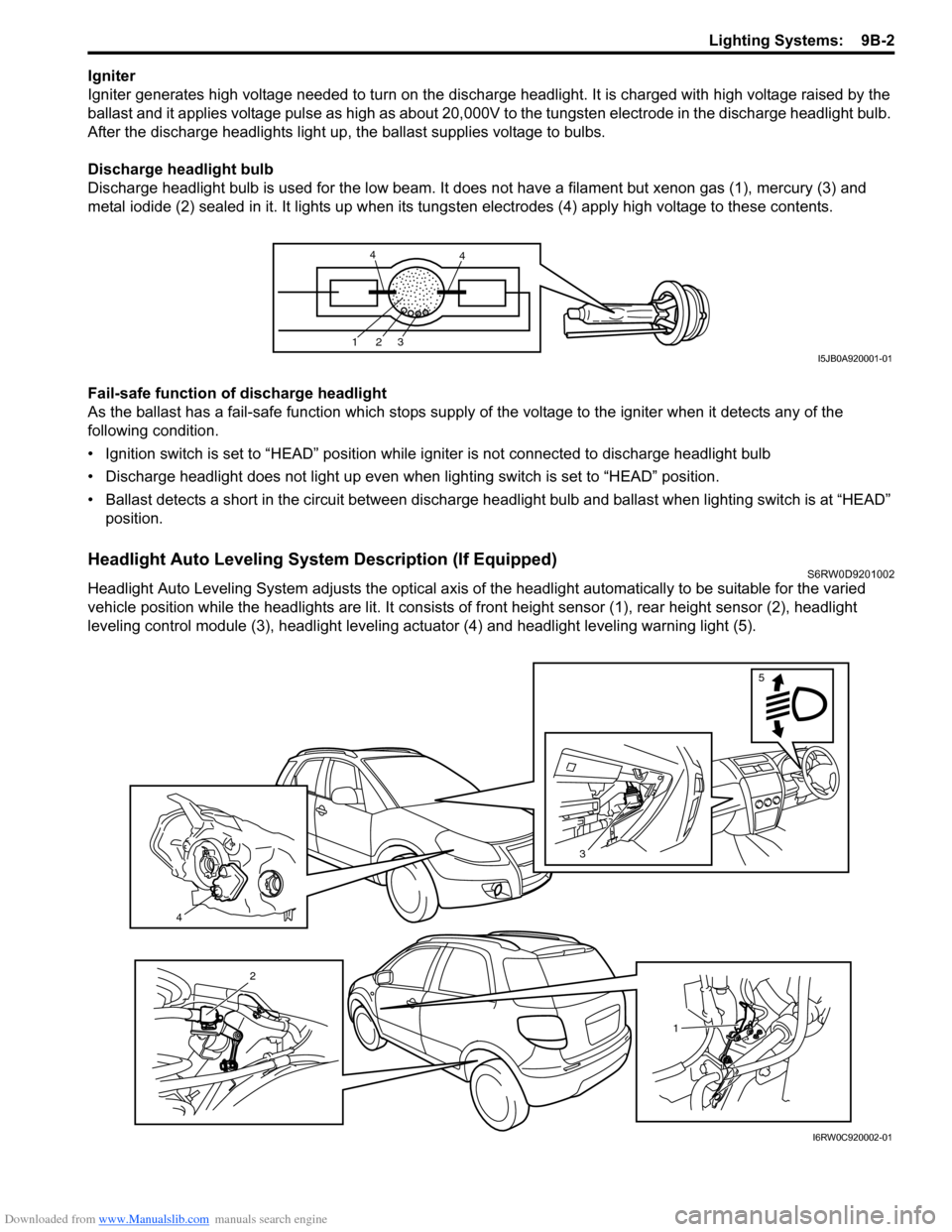
Discharge headlight bulb
Discharge headlight bulb is used for the low beam. It does not have a filament but xenon gas (1), mercury (3) and
metal iodide (2) sealed in it. It lights up when its tungsten electrodes (4) apply high voltage to these contents.
Fail-safe function of discharge headlight
As the ballast has a fail-safe function which stops supply of the voltage to the igniter when it detects any of the
following condition.
• Ignition switch is set to “HEAD” position while igniter is not connected to discharge headlight bulb
• Discharge headlight does not light up even when lighting switch is set to “HEAD” position.
• Ballast detects a short in the circuit between discharge headlight bulb and ballast when lighting switch is at “HEAD”
position.
Headlight Auto Leveling System Description (If Equipped)S6RW0D9201002
Headlight Auto Leveling System adjusts the optical axis of the headlight automatically to be suitable for the varied
vehicle position while the headlights are lit. It consists of front height sensor (1), rear height sensor (2), headlight
leveling control module (3), headlight leveling actuator (4) and headlight leveling warning light (5).
123
44
I5JB0A920001-01
4
3
5
1
2
I6RW0C920002-01