oil SUZUKI SX4 2006 1.G Service Workshop Manual
[x] Cancel search | Manufacturer: SUZUKI, Model Year: 2006, Model line: SX4, Model: SUZUKI SX4 2006 1.GPages: 1556, PDF Size: 37.31 MB
Page 1274 of 1556
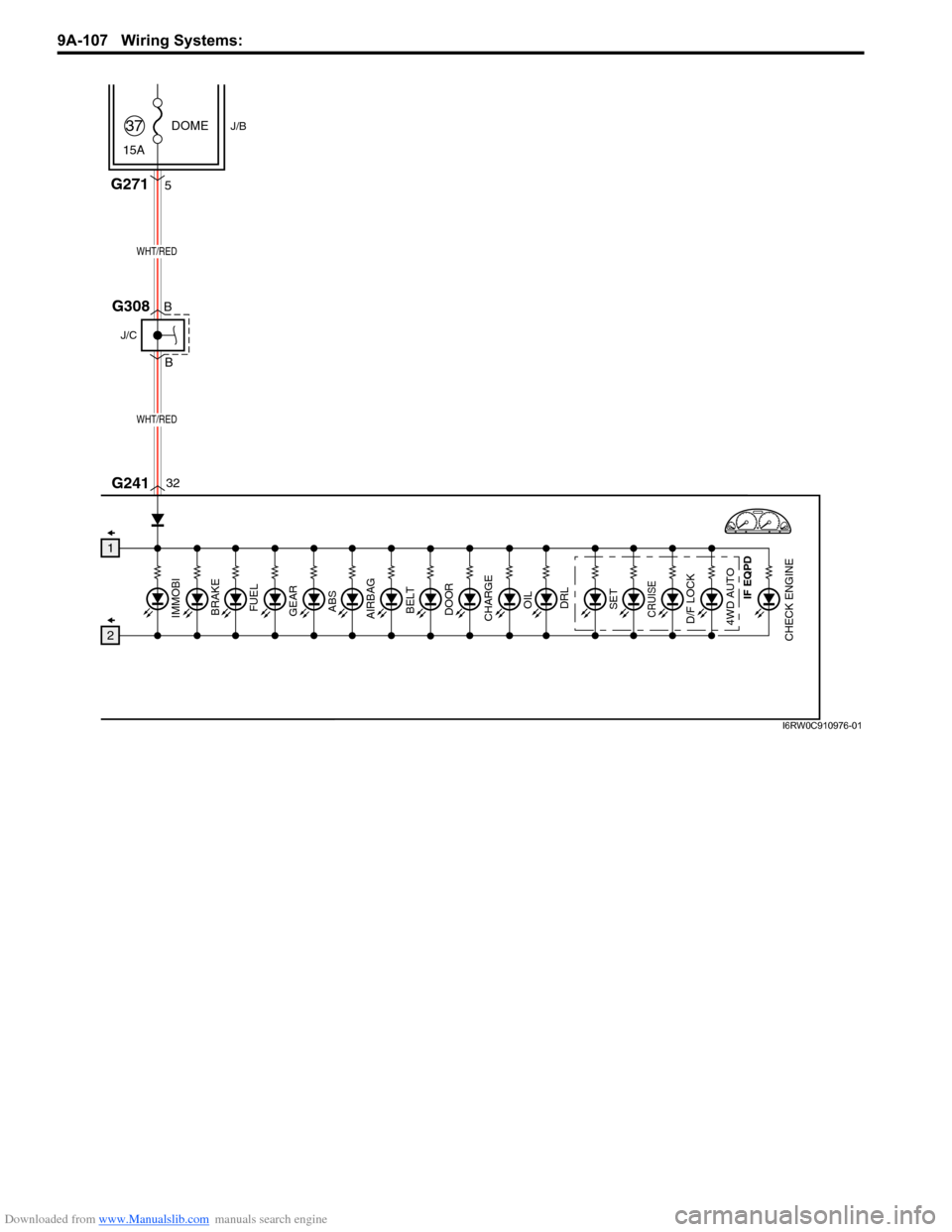
Downloaded from www.Manualslib.com manuals search engine 9A-107 Wiring Systems:
GEAR
ABS
BELT
DOOR
CHARGE
CHECK ENGINEAIRBAG
OILDRLD/F LOCK4WD AUTO
SETCRUISEIMMOBI
BRAKE
FUEL
DOME
15A37
32 5
WHT/RED
WHT/RED
J/B
G271
G241
1
2
J/C
G308B
B
IF EQPD
I6RW0C910976-01
Page 1298 of 1556
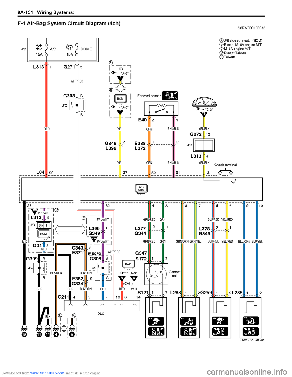
Downloaded from www.Manualslib.com manuals search engine 9A-131 Wiring Systems:
F-1 Air-Bag System Circuit Diagram (4ch)S6RW0D910E032
2
ORN
Y
A/B
SDM
L04
J/B
15AA/B
27
RED
L313
BCM
15
BLK
1
15ADOME
37
WHT/RED
G2715
E388
L3721G349
L3992
PNK/BLK
E40
Forward sensor
1 2
Contact
coil
G347
S172
L377
G3442L399
G34911
L28312S121
YEL/RED
GRN
12
21
YEL/RED
L285 G25912
4
38
75
69
10 2832 27
37
5051
2
"A-8"
L378
G345
ORN
PNK/BLKYEL
YEL
GRN/RED
GRN/REDGRNGRN/ORNGRN/YEL
BLU/RED
BLU/REDBLU/ORNBLU/YEL
L3134
G27213
J/B J/B
"C-3"YB
YEL/BLK
YEL/BLK
J/B side connector (BCM)
Except M16A engine M/T
M16A engine M/T
Except Taiwan
Taiwan A
B
E
D
2 12 1
BCDE
Check terminal
J/C
G308B
B
5
4
C
51114
E382
G33419
C343
E3718
BLK/ORN
BLK/ORNBLK/ORN
7
BLU
PPL/WHT
PPL/WHT
BLU
PPL/WHT
J/C IF EQPD
G308A
A
L313
G043
5
J/CJ/B
G309B
B
DLC
16
WHT
WHT/RED
RED
RW
PW
PW
"A-8"
14 6
BCM
BCM
(CAN)
G2114
BLKBLK
BLK
E
Y"A-8"
D
8A
I6RW0C910A00-01
Page 1299 of 1556
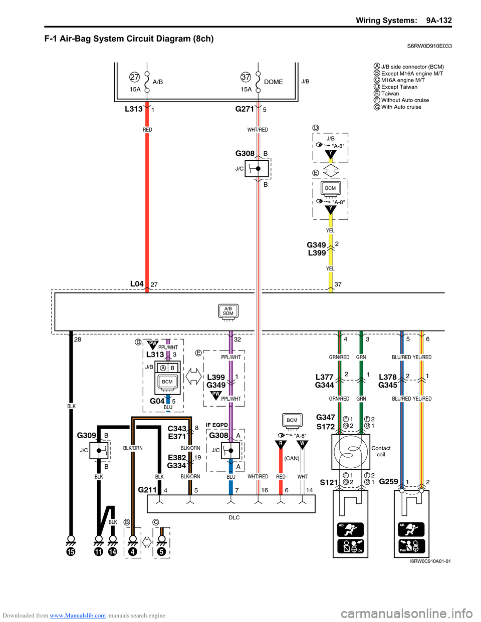
Downloaded from www.Manualslib.com manuals search engine Wiring Systems: 9A-132
F-1 Air-Bag System Circuit Diagram (8ch)S6RW0D910E033
Y
A/B
SDM
L04
J/B
15AA/B
27
REDWHT/RED
L313
BCM
15
BLK
1
15ADOME
37
G2715
2
2832 2737
"A-8"
YEL
YEL
G349
L399
J/C
G308B
B
L399
G3491
5
41114
E382
G33419
C343
E3718
BLK/ORNWHT/RED
BLK/ORNBLK/ORN
7
BLU
PPL/WHT
PPL/WHT
J/C IF EQPD
G308A
A
J/C
G309B
B
DLC
16
WHTRED
RW
PW
"A-8"
14 6
BCM
(CAN)
G2114
BLKBLK
BLK
J/B
E
Y"A-8"
D
B
5
C
D
E
J/B side connector (BCM)
Except M16A engine M/T
M16A engine M/T
Except Taiwan
Taiwan
Without Auto cruise
With Auto cruise ABCDEFG
Contact
coil
G347
S172
L377
G34421
S121
GRN
4
3
GRN/RED
GRN/REDGRN
1
2FG2
1FG
1
2FG2
1FG
BLU
PPL/WHTL313
G043
5
J/B
PW
BCM
8A
G25912
21
5
6
L378
G345
BLU/RED
BLU/RED
YEL/RED
YEL/RED
I6RW0C910A01-01
Page 1306 of 1556
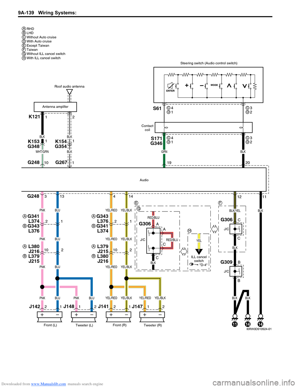
Downloaded from www.Manualslib.com manuals search engine 9A-139 Wiring Systems:
K12112
102102
2
11
22
11
211
G248
G248
BLK
Tweeter (L)Front (L)
J142J148
Tweeter (R)Front (R)
J141
J147
BLK
YEL
BLK
Audio
G306
J/C
ILL cancel
switch
A
A
C
C
G306
J/C
C
C
Steering switch (Audio control switch)
19G26710 120
BLKGRNWHT/GRN
BLK
BLUPNK
BLUPNK
BLUPNK
BLUBLKBLKBLUPNKPNK
YEL/BLKYEL/RED
YEL/BLKYEL/RED
YEL/BLKYEL/RED
YEL/BLKYEL/BLKYEL/REDYEL/RED
S171
G346S61
Roof audio antenna
Contact
coil
Antenna amplifer
4 313 14
K153
G3481
BLK
BLK
K154
G3541
21
G343
L376
G341
L3742112
BLK/YEL
RED/BLU
RED/BLU
G309
J/C
B
B
141114
RHD
LHD
Without Auto cruise
With Auto cruise
Except Taiwan
Taiwan
Without ILL cancel switch
With ILL cancel switch A
E
G
H
A
B
G341
L374
G343
L376A
B
L379
J215
L380
J216A
B
L380
J216
L379
J215A
B
F
BCDEFGH
4
1CD3
2CD
4
1CD3
2CD
Y
"D-4"
I6RW0D910924-01
Page 1320 of 1556
Downloaded from www.Manualslib.com manuals search engine 9B-1 Lighting Systems:
Body, Cab and Accessories
Lighting Systems
Precautions
Precautions for Discharge Headlight Service (If Equipped)S6RW0D9200001
WARNING!
• Do not touch igniter or ballast when lighting switch is at “HEAD” position to avoid possible electric
shock.
• Do not measure voltage or resistance with tester connected to output connector of ballast or igniter
to avoid possible electric shock.
• Do not perform work where exposed to water including rain or with wet hands to avoid possible
electric shock.
• Disassembling igniter or ballast is strictly prohibited as it may cause an electric shock.
• Before inspecting or repairing discharge headlight or its peripheral parts, make sure that lighting
switch is at OFF position and battery is disconnected at negative terminal to avoid possible
electrical shock.
• Do not set lighting switch to “HEAD” position with connector disconnected or any part removed to
avoid possible electric shock.
• Do not touch glass surface of headlight bulb. Oil or grease attached on it may not only make bulb
service life shorter but also cause bulb to burst when lighting switch is turned on.
• Mercury, metal iodide and xenon gas are sealed in discharge headlight bulb. Be sure to dispose of
used discharge headlight bulb properly according to applicable rules or regulations.
Precautions in Diagnosing Troubles (Headlight Auto Leveling System)S6RW0D9200002
• Be sure to read “Air Bag Warning in Section 00” before inspection and observe what is written there.
• Replacement of height sensor and headlight leveling control module. When height sensor and/or headlight leveling
control module is replaced with new one, perform initialization of headlight auto leveling system according to
“Initialization of Headlight Auto Leveling System”.
General Description
Discharge Headlight Description (If Equipped)S6RW0D9201001
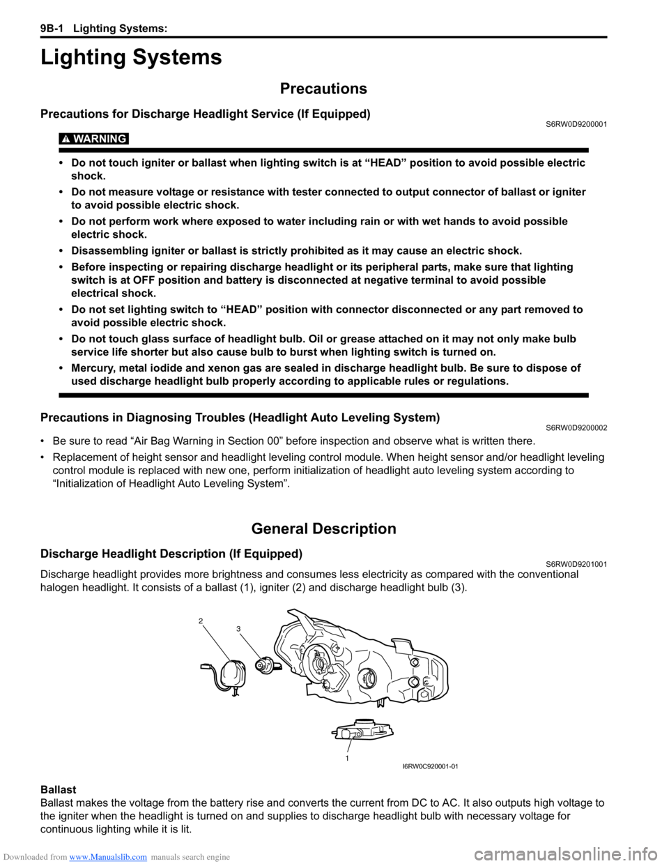
Discharge headlight provides more brightness and consumes less electricity as compared with the conventional
halogen headlight. It consists of a ballast (1), igniter (2) and discharge headlight bulb (3).
Ballast
Ballast makes the voltage from the battery rise and converts the current from DC to AC. It also outputs high voltage to
the igniter when the headlight is turned on and supplies to discharge headlight bulb with necessary voltage for
continuous lighting while it is lit.
2
1 3
I6RW0C920001-01
Page 1329 of 1556
Downloaded from www.Manualslib.com manuals search engine Lighting Systems: 9B-10
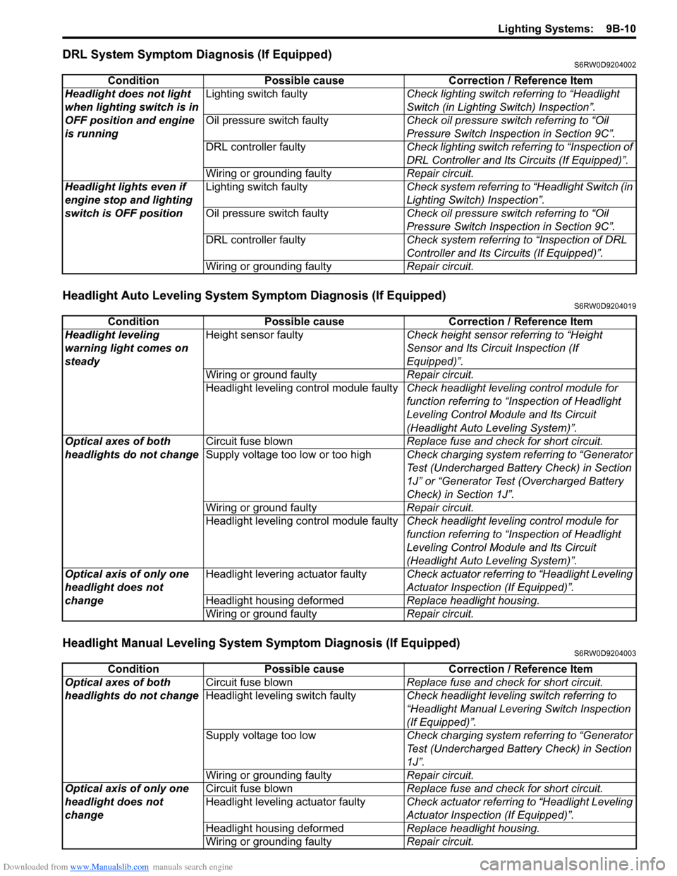
DRL System Symptom Diagnosis (If Equipped)S6RW0D9204002
Headlight Auto Leveling System Symptom Diagnosis (If Equipped)S6RW0D9204019
Headlight Manual Leveling System Symptom Diagnosis (If Equipped)S6RW0D9204003
Condition Possible cause Correction / Reference Item
Headlight does not light
when lighting switch is in
OFF position and engine
is runningLighting switch faultyCheck lighting switch referring to “Headlight
Switch (in Lighting Switch) Inspection”.
Oil pressure switch faultyCheck oil pressure switch referring to “Oil
Pressure Switch Inspection in Section 9C”.
DRL controller faultyCheck lighting switch referring to “Inspection of
DRL Controller and Its Circuits (If Equipped)”.
Wiring or grounding faultyRepair circuit.
Headlight lights even if
engine stop and lighting
switch is OFF positionLighting switch faultyCheck system referring to “Headlight Switch (in
Lighting Switch) Inspection”.
Oil pressure switch faultyCheck oil pressure switch referring to “Oil
Pressure Switch Inspection in Section 9C”.
DRL controller faultyCheck system referring to “Inspection of DRL
Controller and Its Circuits (If Equipped)”.
Wiring or grounding faultyRepair circuit.
Condition Possible cause Correction / Reference Item
Headlight leveling
warning light comes on
steadyHeight sensor faultyCheck height sensor referring to “Height
Sensor and Its Circuit Inspection (If
Equipped)”.
Wiring or ground faultyRepair circuit.
Headlight leveling control module faultyCheck headlight leveling control module for
function referring to “Inspection of Headlight
Leveling Control Module and Its Circuit
(Headlight Auto Leveling System)”.
Optical axes of both
headlights do not changeCircuit fuse blownReplace fuse and check for short circuit.
Supply voltage too low or too highCheck charging system referring to “Generator
Test (Undercharged Battery Check) in Section
1J” or “Generator Test (Overcharged Battery
Check) in Section 1J”.
Wiring or ground faultyRepair circuit.
Headlight leveling control module faultyCheck headlight leveling control module for
function referring to “Inspection of Headlight
Leveling Control Module and Its Circuit
(Headlight Auto Leveling System)”.
Optical axis of only one
headlight does not
changeHeadlight levering actuator faultyCheck actuator referring to “Headlight Leveling
Actuator Inspection (If Equipped)”.
Headlight housing deformedReplace headlight housing.
Wiring or ground faultyRepair circuit.
Condition Possible cause Correction / Reference Item
Optical axes of both
headlights do not changeCircuit fuse blownReplace fuse and check for short circuit.
Headlight leveling switch faultyCheck headlight leveling switch referring to
“Headlight Manual Levering Switch Inspection
(If Equipped)”.
Supply voltage too lowCheck charging system referring to “Generator
Test (Undercharged Battery Check) in Section
1J”.
Wiring or grounding faultyRepair circuit.
Optical axis of only one
headlight does not
changeCircuit fuse blownReplace fuse and check for short circuit.
Headlight leveling actuator faultyCheck actuator referring to “Headlight Leveling
Actuator Inspection (If Equipped)”.
Headlight housing deformedReplace headlight housing.
Wiring or grounding faultyRepair circuit.
Page 1332 of 1556
Downloaded from www.Manualslib.com manuals search engine 9B-13 Lighting Systems:
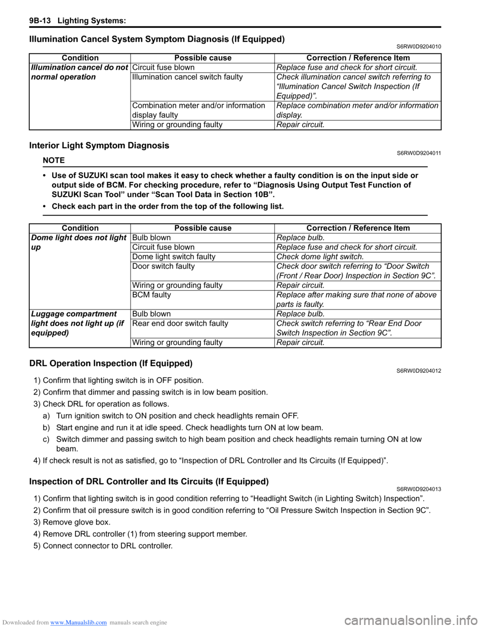
Illumination Cancel System Symptom Diagnosis (If Equipped)S6RW0D9204010
Interior Light Symptom DiagnosisS6RW0D9204011
NOTE
• Use of SUZUKI scan tool makes it easy to check whether a faulty condition is on the input side or
output side of BCM. For checking procedure, refer to “Diagnosis Using Output Test Function of
SUZUKI Scan Tool” under “Scan Tool Data in Section 10B”.
• Check each part in the order from the top of the following list.
DRL Operation Inspection (If Equipped)S6RW0D9204012
1) Confirm that lighting switch is in OFF position.
2) Confirm that dimmer and passing switch is in low beam position.
3) Check DRL for operation as follows.
a) Turn ignition switch to ON position and check headlights remain OFF.
b) Start engine and run it at idle speed. Check headlights turn ON at low beam.
c) Switch dimmer and passing switch to high beam position and check headlights remain turning ON at low
beam.
4) If check result is not as satisfied, go to “Inspection of DRL Controller and Its Circuits (If Equipped)”.
Inspection of DRL Controller and Its Circuits (If Equipped)S6RW0D9204013
1) Confirm that lighting switch is in good condition referring to “Headlight Switch (in Lighting Switch) Inspection”.
2) Confirm that oil pressure switch is in good condition referring to “Oil Pressure Switch Inspection in Section 9C”.
3) Remove glove box.
4) Remove DRL controller (1) from steering support member.
5) Connect connector to DRL controller.Condition Possible cause Correction / Reference Item
Illumination cancel do not
normal operationCircuit fuse blownReplace fuse and check for short circuit.
Illumination cancel switch faultyCheck illumination cancel switch referring to
“Illumination Cancel Switch Inspection (If
Equipped)”.
Combination meter and/or information
display faultyReplace combination meter and/or information
display.
Wiring or grounding faultyRepair circuit.
Condition Possible cause Correction / Reference Item
Dome light does not light
upBulb blownReplace bulb.
Circuit fuse blownReplace fuse and check for short circuit.
Dome light switch faultyCheck dome light switch.
Door switch faultyCheck door switch referring to “Door Switch
(Front / Rear Door) Inspection in Section 9C”.
Wiring or grounding faultyRepair circuit.
BCM faultyReplace after making sure that none of above
parts is faulty.
Luggage compartment
light does not light up (if
equipped)Bulb blownReplace bulb.
Rear end door switch faultyCheck switch referring to “Rear End Door
Switch Inspection in Section 9C”.
Wiring or grounding faultyRepair circuit.
Page 1333 of 1556
Downloaded from www.Manualslib.com manuals search engine Lighting Systems: 9B-14
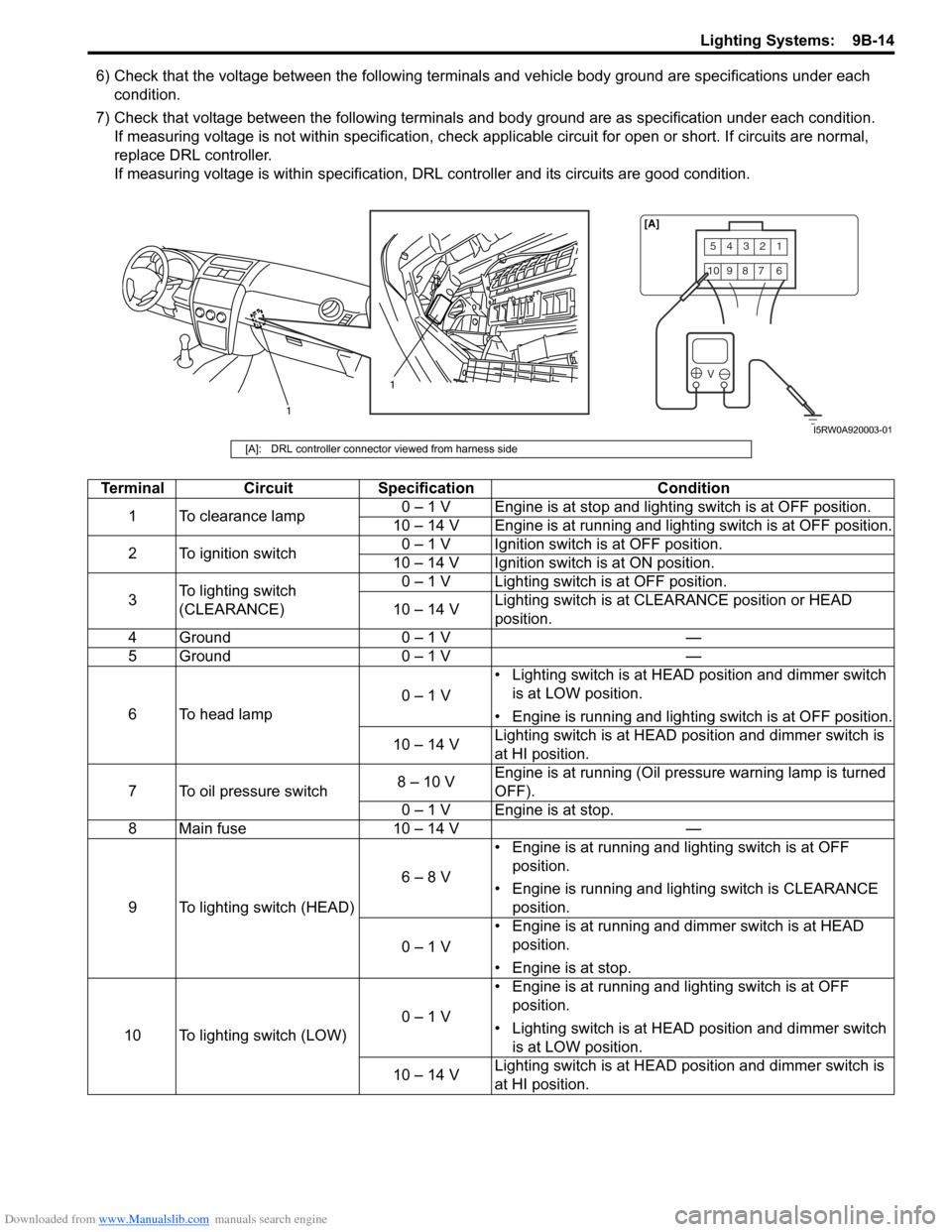
6) Check that the voltage between the following terminals and vehicle body ground are specifications under each
condition.
7) Check that voltage between the following terminals and body ground are as specification under each condition.
If measuring voltage is not within specification, check applicable circuit for open or short. If circuits are normal,
replace DRL controller.
If measuring voltage is within specification, DRL controller and its circuits are good condition.
54321
10987 6
V
1
1[A]
I5RW0A920003-01
[A]: DRL controller connector viewed from harness side
Terminal Circuit Specification Condition
1 To clearance lamp0 – 1 V Engine is at stop and lighting switch is at OFF position.
10 – 14 V Engine is at running and lighting switch is at OFF position.
2 To ignition switch0 – 1 V Ignition switch is at OFF position.
10 – 14 V Ignition switch is at ON position.
3To lighting switch
(CLEARANCE)0 – 1 V Lighting switch is at OFF position.
10 – 14 VLighting switch is at CLEARANCE position or HEAD
position.
4 Ground 0 – 1 V —
5 Ground 0 – 1 V —
6 To head lamp0 – 1 V• Lighting switch is at HEAD position and dimmer switch
is at LOW position.
• Engine is running and lighting switch is at OFF position.
10 – 14 VLighting switch is at HEAD position and dimmer switch is
at HI position.
7 To oil pressure switch8 – 10 VEngine is at running (Oil pressure warning lamp is turned
OFF).
0 – 1 V Engine is at stop.
8 Main fuse 10 – 14 V —
9 To lighting switch (HEAD)6 – 8 V• Engine is at running and lighting switch is at OFF
position.
• Engine is running and lighting switch is CLEARANCE
position.
0 – 1 V• Engine is at running and dimmer switch is at HEAD
position.
• Engine is at stop.
10 To lighting switch (LOW)0 – 1 V• Engine is at running and lighting switch is at OFF
position.
• Lighting switch is at HEAD position and dimmer switch
is at LOW position.
10 – 14 VLighting switch is at HEAD position and dimmer switch is
at HI position.
Page 1348 of 1556
Downloaded from www.Manualslib.com manuals search engine 9B-29 Lighting Systems:
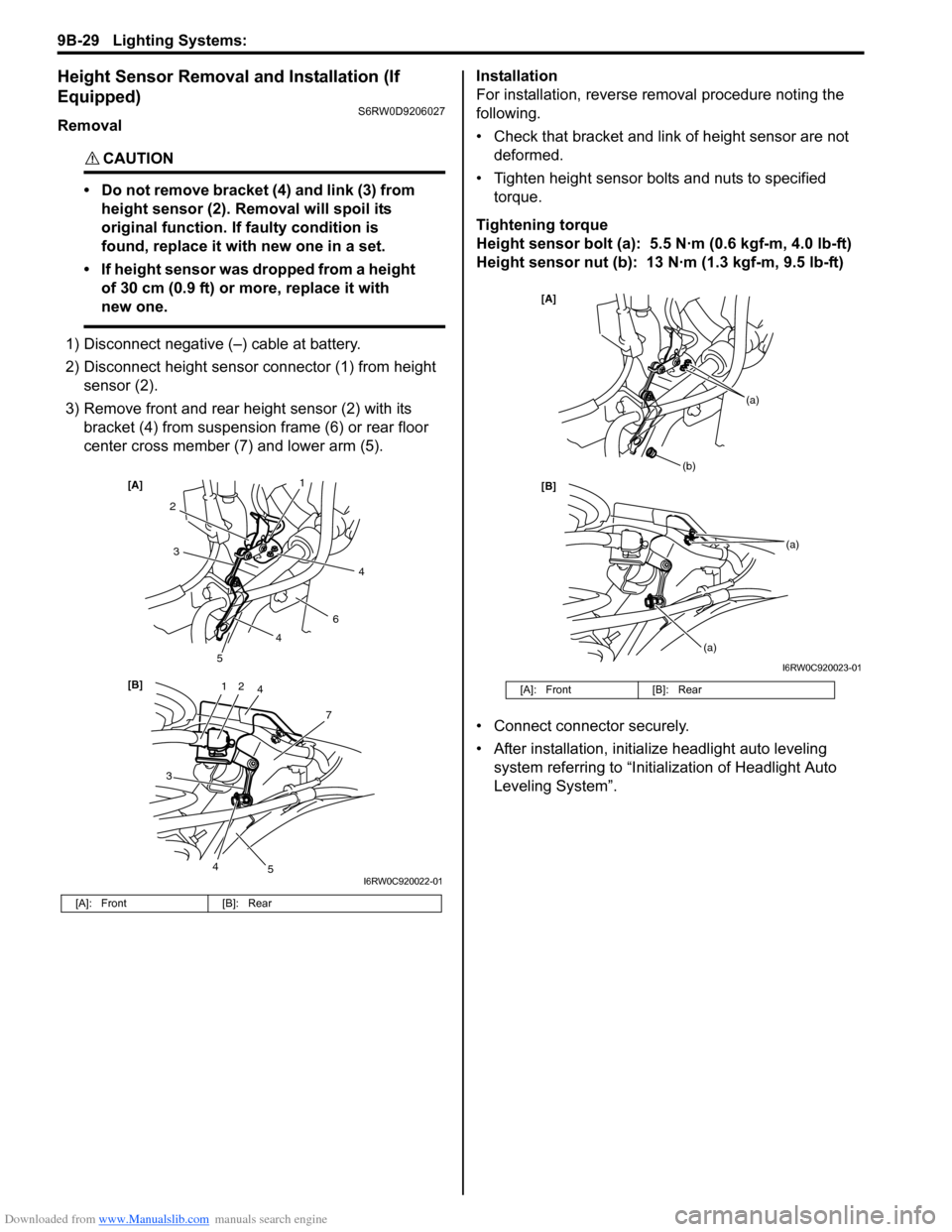
Height Sensor Removal and Installation (If
Equipped)
S6RW0D9206027
Removal
CAUTION!
• Do not remove bracket (4) and link (3) from
height sensor (2). Removal will spoil its
original function. If faulty condition is
found, replace it with new one in a set.
• If height sensor was dropped from a height
of 30 cm (0.9 ft) or more, replace it with
new one.
1) Disconnect negative (–) cable at battery.
2) Disconnect height sensor connector (1) from height
sensor (2).
3) Remove front and rear height sensor (2) with its
bracket (4) from suspension frame (6) or rear floor
center cross member (7) and lower arm (5).Installation
For installation, reverse removal procedure noting the
following.
• Check that bracket and link of height sensor are not
deformed.
• Tighten height sensor bolts and nuts to specified
torque.
Tightening torque
Height sensor bolt (a): 5.5 N·m (0.6 kgf-m, 4.0 lb-ft)
Height sensor nut (b): 13 N·m (1.3 kgf-m, 9.5 lb-ft)
• Connect connector securely.
• After installation, initialize headlight auto leveling
system referring to “Initialization of Headlight Auto
Leveling System”.
[A]: Front [B]: Rear
12
7
[B] [A]
4
3
2
6
3
5
5
1
4
4
4
I6RW0C920022-01
[A]: Front [B]: Rear
[B] [A]
(b)
(a)
(a)
(a)
I6RW0C920023-01
Page 1354 of 1556
Downloaded from www.Manualslib.com manuals search engine 9C-2 Instrumentation / Driver Info. / Horn:
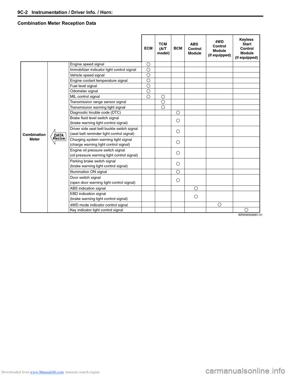
Combination Meter Reception Data
ECM BCM
Keyless
Start
Control
Module
(if equipped)
Combination
Meter4WD
Control
Module
(if equipped)TCM
(A/T
model)
Engine speed signal
Immobilizer indicator light control signal
Vehicle speed signal
Engine coolant temperature signal
Fuel level signal
MIL control signal
Transmission range sensor signal
Transmission warning light signal
Diagnostic trouble code (DTC)
Brake fluid level switch signal
(brake warning light control signal)
Driver side seat belt buckle switch signal
(seat belt reminder light control signal)
Charging system warning light signal
(charge warning light control signal)
Engine oil pressure switch signal
(oil pressure warning light control signal)
Parking brake switch signal
(brake warning light control signal)
Illumination ON signal
Door switch signal
(open door warning light control signal)
ABS indication signal
EBD indication signal
(brake warning light control signal)
4WD mode indicator control signal
Key indicator light control signal
ABS
Control
Module
Odometer signal
DATA
Recive
I6RW0D930001-01