Timing SUZUKI SX4 2006 1.G Service Repair Manual
[x] Cancel search | Manufacturer: SUZUKI, Model Year: 2006, Model line: SX4, Model: SUZUKI SX4 2006 1.GPages: 1556, PDF Size: 37.31 MB
Page 399 of 1556
Downloaded from www.Manualslib.com manuals search engine Ignition System: 1H-4
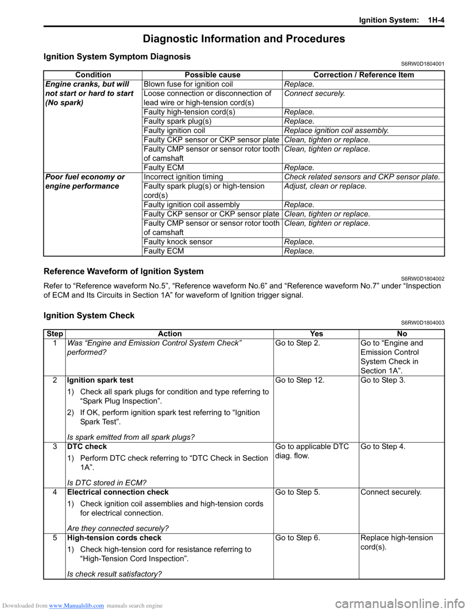
Diagnostic Information and Procedures
Ignition System Symptom DiagnosisS6RW0D1804001
Reference Waveform of Ignition SystemS6RW0D1804002
Refer to “Reference waveform No.5”, “Reference waveform No.6” and “Reference waveform No.7” under “Inspection
of ECM and Its Circuits in Section 1A” for waveform of Ignition trigger signal.
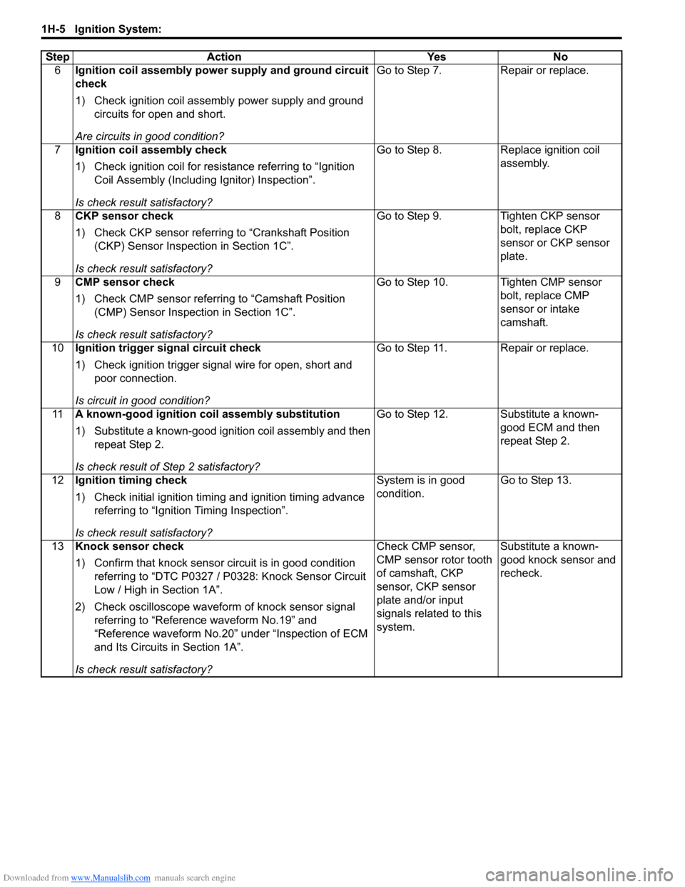
Ignition System CheckS6RW0D1804003
Condition Possible cause Correction / Reference Item
Engine cranks, but will
not start or hard to start
(No spark)Blown fuse for ignition coilReplace.
Loose connection or disconnection of
lead wire or high-tension cord(s)Connect securely.
Faulty high-tension cord(s)Replace.
Faulty spark plug(s)Replace.
Faulty ignition coilReplace ignition coil assembly.
Faulty CKP sensor or CKP sensor plateClean, tighten or replace.
Faulty CMP sensor or sensor rotor tooth
of camshaftClean, tighten or replace.
Faulty ECMReplace.
Poor fuel economy or
engine performanceIncorrect ignition timingCheck related sensors and CKP sensor plate.
Faulty spark plug(s) or high-tension
cord(s)Adjust, clean or replace.
Faulty ignition coil assemblyReplace.
Faulty CKP sensor or CKP sensor plateClean, tighten or replace.
Faulty CMP sensor or sensor rotor tooth
of camshaftClean, tighten or replace.
Faulty knock sensorReplace.
Faulty ECMReplace.
Step Action Yes No
1Was “Engine and Emission Control System Check”
performed?Go to Step 2. Go to “Engine and
Emission Control
System Check in
Section 1A”.
2Ignition spark test
1) Check all spark plugs for condition and type referring to
“Spark Plug Inspection”.
2) If OK, perform ignition spark test referring to “Ignition
Spar k Tes t”.
Is spark emitted from all spark plugs?Go to Step 12. Go to Step 3.
3DTC check
1) Perform DTC check referring to “DTC Check in Section
1A”.
Is DTC stored in ECM?Go to applicable DTC
diag. flow.Go to Step 4.
4Electrical connection check
1) Check ignition coil assemblies and high-tension cords
for electrical connection.
Are they connected securely?Go to Step 5. Connect securely.
5High-tension cords check
1) Check high-tension cord for resistance referring to
“High-Tension Cord Inspection”.
Is check result satisfactory?Go to Step 6. Replace high-tension
cord(s).
Page 400 of 1556
Downloaded from www.Manualslib.com manuals search engine 1H-5 Ignition System:
6Ignition coil assembly power supply and ground circuit
check
1) Check ignition coil assembly power supply and ground
circuits for open and short.
Are circuits in good condition?Go to Step 7. Repair or replace.
7Ignition coil assembly check
1) Check ignition coil for resistance referring to “Ignition
Coil Assembly (Including Ignitor) Inspection”.
Is check result satisfactory?Go to Step 8. Replace ignition coil
assembly.
8CKP sensor check
1) Check CKP sensor referring to “Crankshaft Position
(CKP) Sensor Inspection in Section 1C”.
Is check result satisfactory?Go to Step 9. Tighten CKP sensor
bolt, replace CKP
sensor or CKP sensor
plate.
9CMP sensor check
1) Check CMP sensor referring to “Camshaft Position
(CMP) Sensor Inspection in Section 1C”.
Is check result satisfactory?Go to Step 10. Tighten CMP sensor
bolt, replace CMP
sensor or intake
camshaft.
10Ignition trigger signal circuit check
1) Check ignition trigger signal wire for open, short and
poor connection.
Is circuit in good condition?Go to Step 11. Repair or replace.
11A known-good ignition coil assembly substitution
1) Substitute a known-good ignition coil assembly and then
repeat Step 2.
Is check result of Step 2 satisfactory?Go to Step 12. Substitute a known-
good ECM and then
repeat Step 2.
12Ignition timing check
1) Check initial ignition timing and ignition timing advance
referring to “Ignition Timing Inspection”.
Is check result satisfactory?System is in good
condition.Go to Step 13.
13Knock sensor check
1) Confirm that knock sensor circuit is in good condition
referring to “DTC P0327 / P0328: Knock Sensor Circuit
Low / High in Section 1A”.
2) Check oscilloscope waveform of knock sensor signal
referring to “Reference waveform No.19” and
“Reference waveform No.20” under “Inspection of ECM
and Its Circuits in Section 1A”.
Is check result satisfactory?Check CMP sensor,
CMP sensor rotor tooth
of camshaft, CKP
sensor, CKP sensor
plate and/or input
signals related to this
system.Substitute a known-
good knock sensor and
recheck. Step Action Yes No
Page 403 of 1556
Downloaded from www.Manualslib.com manuals search engine Ignition System: 1H-8
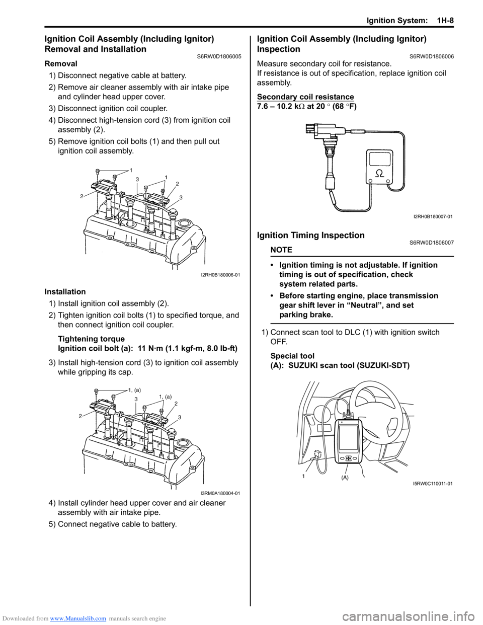
Ignition Coil Assembly (Including Ignitor)
Removal and Installation
S6RW0D1806005
Removal
1) Disconnect negative cable at battery.
2) Remove air cleaner assembly with air intake pipe
and cylinder head upper cover.
3) Disconnect ignition coil coupler.
4) Disconnect high-tension cord (3) from ignition coil
assembly (2).
5) Remove ignition coil bolts (1) and then pull out
ignition coil assembly.
Installation
1) Install ignition coil assembly (2).
2) Tighten ignition coil bolts (1) to specified torque, and
then connect ignition coil coupler.
Tightening torque
Ignition coil bolt (a): 11 N·m (1.1 kgf-m, 8.0 lb-ft)
3) Install high-tension cord (3) to ignition coil assembly
while gripping its cap.
4) Install cylinder head upper cover and air cleaner
assembly with air intake pipe.
5) Connect negative cable to battery.
Ignition Coil Assembly (Including Ignitor)
Inspection
S6RW0D1806006
Measure secondary coil for resistance.
If resistance is out of specification, replace ignition coil
assembly.
Secondary coil resistance
7.6 – 10.2 kΩ at 20 ° (68 °F)
Ignition Timing InspectionS6RW0D1806007
NOTE
• Ignition timing is not adjustable. If ignition
timing is out of specification, check
system related parts.
• Before starting engine, place transmission
gear shift lever in “Neutral”, and set
parking brake.
1) Connect scan tool to DLC (1) with ignition switch
OFF.
Special tool
(A): SUZUKI scan tool (SUZUKI-SDT)
I2RH0B180006-01
I3RM0A180004-01
I2RH0B180007-01
(A) 1I 5 R W 0 C 11 0 0 11 - 0 1
Page 404 of 1556
Downloaded from www.Manualslib.com manuals search engine 1H-9 Ignition System:
2) Start engine and warm it up to normal operating
temperature.
3) Make sure that all of electrical loads except ignition
are switched off.
4) Check to be sure that idle speed is within
specification.
5) Fix ignition timing by using “Fixed Spark Control” of
“Engine / Active Test” mode on scan tool.
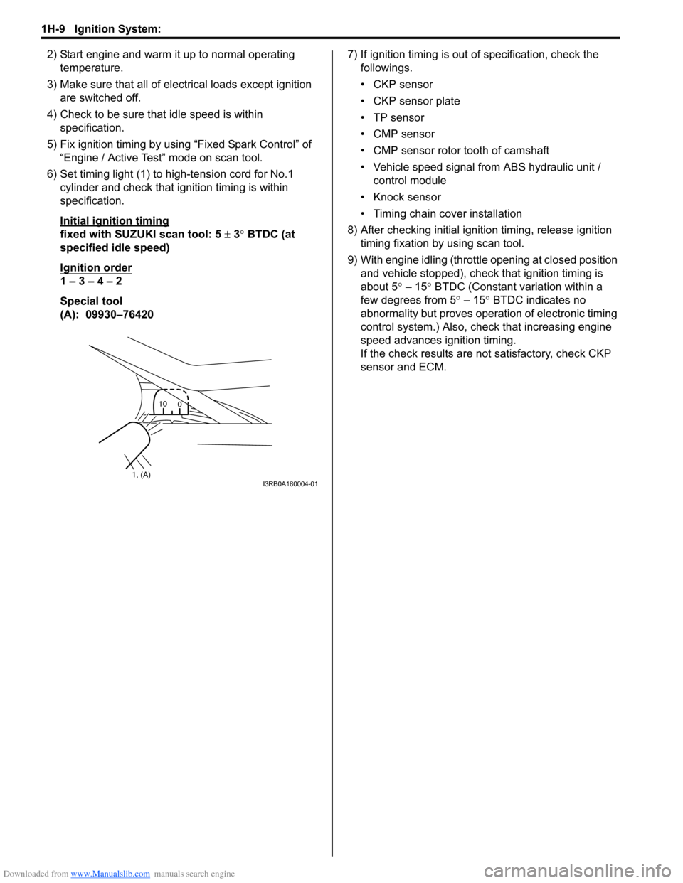
6) Set timing light (1) to high-tension cord for No.1
cylinder and check that ignition timing is within
specification.
Initial ignition timing
fixed with SUZUKI scan tool: 5 ± 3° BTDC (at
specified idle speed)
Ignition order
1 – 3 – 4 – 2
Special tool
(A): 09930–764207) If ignition timing is out of specification, check the
followings.
• CKP sensor
• CKP sensor plate
• TP sensor
• CMP sensor
• CMP sensor rotor tooth of camshaft
• Vehicle speed signal from ABS hydraulic unit /
control module
• Knock sensor
• Timing chain cover installation
8) After checking initial ignition timing, release ignition
timing fixation by using scan tool.
9) With engine idling (throttle opening at closed position
and vehicle stopped), check that ignition timing is
about 5° – 15° BTDC (Constant variation within a
few degrees from 5° – 15° BTDC indicates no
abnormality but proves operation of electronic timing
control system.) Also, check that increasing engine
speed advances ignition timing.
If the check results are not satisfactory, check CKP
sensor and ECM.
1, (A)10
0I3RB0A180004-01
Page 405 of 1556
Downloaded from www.Manualslib.com manuals search engine Ignition System: 1H-10
Specifications
Tightening Torque SpecificationsS6RW0D1807001
Reference:
For the tightening torque of fastener not specified in this section, refer to “Fasteners Information in Section 0A”.
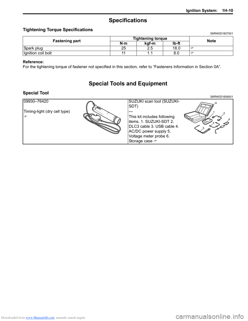
Special Tools and Equipment
Special ToolS6RW0D1808001
Fastening partTightening torque
Note
N⋅mkgf-mlb-ft
Spark plug 25 2.5 18.0�)
Ignition coil bolt 11 1.1 8.0�)
09930–76420 SUZUKI scan tool (SUZUKI-
SDT)
Timing-light (dry cell type) —
�)This kit includes following
items. 1. SUZUKI-SDT 2.
DLC3 cable 3. USB cable 4.
AC/DC power supply 5.
Voltage meter probe 6.
Storage case �)
1
2
34
56
Page 645 of 1556
Downloaded from www.Manualslib.com manuals search engine Table of Contents 5- i
5
Section 5
CONTENTS
Transmission / Transaxle
Precautions ................................................. 5-1
Precautions............................................................. 5-1
Precautions on Transmission / Transaxle ............. 5-1
Automatic Transmission/Transaxle ....... 5A-1
Precautions........................................................... 5A-1
Precautions in Diagnosing Trouble ..................... 5A-1
Precautions for Disassembly and
Reassembly ...................................................... 5A-1
General Description ............................................. 5A-3
A/T Description ................................................... 5A-3
Clutch / Brake / Planetary Gear Function of
Automatic Transaxle ......................................... 5A-6
Table of Component Operation ........................... 5A-7
A/T Diagnosis General Description ..................... 5A-7
On-Board Diagnostic System Description ........... 5A-8
CAN Communication System Description........... 5A-9
Schematic and Routing Diagram ...................... 5A-10
Transmission Control Module (TCM) Wiring
Diagram .......................................................... 5A-10
Automatic Gear Shift Table ............................... 5A-12
Component Location ......................................... 5A-14
Electronic Shift Control System Components
Location .......................................................... 5A-14
Diagnostic Information and Procedures .......... 5A-16
A/T System Check ............................................ 5A-16
Visual Inspection ............................................... 5A-18
Malfunction Indicator Lamp (MIL) Check .......... 5A-19
Transmission Warning Light Check (Non-
Euro-OBD model) ........................................... 5A-19
DTC Table ......................................................... 5A-19
DTC Check ....................................................... 5A-21
DTC Clearance ................................................. 5A-22
Fail-Safe Table .................................................. 5A-22
Scan Tool Data ................................................. 5A-24
A/T Basic Check ............................................... 5A-27
Road Test ......................................................... 5A-27
Manual Road Test ............................................. 5A-30
Engine Brake Test ............................................ 5A-30
Stall Test ........................................................... 5A-31
Time Lag Test ................................................... 5A-32
Line Pressure Test ............................................ 5A-32
“P” Range Test.................................................. 5A-33
A/T Symptom Diagnosis ................................... 5A-34Transmission Warning Light Circuit Check –
Light Remains “ON” at Ignition Switch ON
(Non-Euro-OBD Model)................................... 5A-41
Transmission Warning Light Circuit Check –
Light Does Not Come “ON” at Ignition Switch
ON (Non-Euro-OBD Model)............................ 5A-41
DTC P0602: Control Module Programming
Error ................................................................ 5A-42
DTC P0705: Transmission Range Sensor
Circuit Malfunction (PRNDL Input) .................. 5A-42
DTC P0707: Transmission Range Sensor
Circuit Low ...................................................... 5A-44
DTC P0711: Transmission Fluid Temperature
Sensor “A” Control Range / Performance ....... 5A-46
DTC P0712: Transmission Fluid Temperature
Sensor Circuit Low .......................................... 5A-47
DTC P0713: Transmission Fluid Temperature
Sensor Circuit High ......................................... 5A-48
DTC P0717: Input / Turbine Speed Sensor
Circuit Malfunction........................................... 5A-50
DTC P0722: Output Speed Sensor (VSS)
Circuit No Signal ............................................. 5A-51
DTC P0741 / P0742: TCC Circuit
Performance or Stuck OFF / TCC Circuit
Stuck ON ......................................................... 5A-53
DTC P0751 / P0752 / P0756 / P0757: Shift
Solenoid Malfunction ....................................... 5A-54
DTC P0787: Shift / Timing Solenoid Control
Circuit Low ...................................................... 5A-55
DTC P0788: Shift / Timing Solenoid Control
Circuit High...................................................... 5A-57
DTC P0961: Pressure Control Solenoid “A”
Control Circuit Range / Performance .............. 5A-58
DTC P0962: Pressure Control Solenoid
Control Circuit Low .......................................... 5A-60
DTC P0963: Pressure Control Solenoid
Control Circuit High ......................................... 5A-62
DTC P0973 / P0976: Shift Solenoid-A (No.1)
Control Circuit Low / Shift Solenoid-B (No.2)
Control Circuit Low .......................................... 5A-64
DTC P0974 / P0977: Shift Solenoid-A (No.1)
/ Shift Solenoid-B (No.2) Control Circuit High .. 5A-66
DTC P1702: Internal Control Module Memory
Check Sum Error............................................. 5A-68
Page 646 of 1556
Downloaded from www.Manualslib.com manuals search engine 5-ii Table of Contents
DTC P1723: Range Select Switch
Malfunction ...................................................... 5A-68
DTC P1878: Torque Converter Clutch
Shudder .......................................................... 5A-69
DTC P2762: Torque Converter Clutch (TCC)
Pressure Control Solenoid Control Circuit
Range / Performance ...................................... 5A-70
DTC P2763: Torque Converter Clutch (TCC)
Pressure Control Solenoid Control Circuit
High ................................................................. 5A-72
DTC P2764: Torque Converter Clutch (TCC)
Circuit Pressure Control Solenoid Control
Circuit Low ...................................................... 5A-74
DTC U0073: Control Module Communication
Bus Off ............................................................ 5A-76
DTC U0100: Lost Communication with ECM /
PCM “A” .......................................................... 5A-76
Inspection of TCM and Its Circuits .................... 5A-76
TCM Power and Ground Circuit Check ............. 5A-80
Brake Interlock System Inspection .................... 5A-81
Repair Instructions ............................................5A-82
Learning Control Initialization ............................ 5A-82
A/T Fluid Level Check ....................................... 5A-82
A/T Fluid Change .............................................. 5A-83
Select Lever Components ................................. 5A-84
Select Lever Assembly Removal and
Installation ....................................................... 5A-84
Select Lever Knob Installation........................... 5A-84
Select Lever Inspection ..................................... 5A-85
“3” Position Switch Inspection ........................... 5A-85
Shift Lock Solenoid Inspection .......................... 5A-85
Shift Lock Solenoid Replacement ..................... 5A-85
Select Cable Components ................................ 5A-86
Select Cable Removal and Installation ............. 5A-86
Select Cable Adjustment ................................... 5A-86
Key Interlock Cable Removal and Installation... 5A-87
Transmission Range Sensor Inspection and
Adjustment ...................................................... 5A-89
Output Shaft Speed Sensor (VSS) Removal
and Installation ................................................ 5A-90
Output Shaft Speed Sensor (VSS) Inspection .. 5A-90
Input Shaft Speed Sensor Removal and
Installation ....................................................... 5A-91
Input Shaft Speed Sensor Inspection................ 5A-91
Transmission Fluid Temperature Sensor
Removal and Installation ................................. 5A-91
Transmission Fluid Temperature Sensor
Inspection ........................................................ 5A-92
Solenoid Valves (Shift Solenoid Valves and
Timing Solenoid Valve) Removal and
Installation ....................................................... 5A-92
Solenoid Valves (Shift Solenoid Valves and
Timing Solenoid Valve) Inspection .................. 5A-94
Pressure Control Solenoid Valves (Pressure
Control Solenoid and TCC Solenoid)
Removal and Installation ................................. 5A-95
Pressure Control Solenoid Valves Inspection ... 5A-96
Transmission Control Module (TCM)
Removal and Installation ................................. 5A-97
A/T Relay Inspection ......................................... 5A-97Differential Side Oil Seal Replacement ............. 5A-98
A/T Fluid Cooler Hoses Replacement ............... 5A-98
Automatic Transaxle Unit Components............. 5A-99
Automatic Transaxle Unit Dismounting and
Remounting ................................................... 5A-100
Automatic Transaxle Assembly Components . 5A-102
Automatic Transaxle Unit Disassembly........... 5A-104
Oil Pump Assembly Components ................... 5A-116
Oil Pump Assembly Disassembly and
Reassembly .................................................. 5A-116
Oil Pump Assembly Inspection ....................... 5A-117
Direct Clutch Assembly Components.............. 5A-119
Direct Clutch Assembly Preliminary Check ..... 5A-119
Direct Clutch Assembly Disassembly and
Reassembly .................................................. 5A-120
Direct Clutch Assembly Inspection.................. 5A-122
Forward and Reverse Clutch Assembly
Components .................................................. 5A-123
Forward and Reverse Clutch Assembly
Preliminary Check ......................................... 5A-123
Forward and Reverse Clutch Assembly
Disassembly and Reassembly ...................... 5A-124
Forward and Reverse Clutch Assembly
Inspection ...................................................... 5A-127
2nd Brake Piston Assembly Components ....... 5A-128
2nd Brake Piston Assembly Disassembly and
Reassembly .................................................. 5A-128
Transaxle Rear Cover (O/D and 2nd Coast
Brake Piston) Assembly Components........... 5A-129
Transaxle Rear Cover (O/D and 2nd Coast
Brake Piston) Assembly Disassembly and
Reassembly .................................................. 5A-130
Transaxle Rear Cover (O/D and 2nd Coast
Brake Piston) Assembly Inspection............... 5A-131
Countershaft Assembly Components.............. 5A-132
Countershaft Assembly Disassembly and
Reassembly .................................................. 5A-132
Valve Body Assembly Components ................ 5A-133
Valve Body Assembly Disassembly and
Reassembly .................................................. 5A-134
Differential Assembly Components ................. 5A-135
Differential Assembly Disassembly and
Reassembly .................................................. 5A-136
Differential Assembly Inspection ..................... 5A-137
Torque Converter Housing Disassembly and
Reassembly .................................................. 5A-138
Transaxle Case Disassembly and
Reassembly .................................................. 5A-140
Automatic Transaxle Unit Inspection and
Adjustment .................................................... 5A-141
Automatic Transaxle Unit Assembly ............... 5A-144
Specifications ...................................................5A-161
Tightening Torque Specifications .................... 5A-161
Special Tools and Equipment .........................5A-162
Recommended Service Material ..................... 5A-162
Special Tool .................................................... 5A-162
Manual Transmission/Transaxle ............ 5B-1
General Description .............................................5B-1
Manual Transaxle Construction .......................... 5B-1
Page 651 of 1556
Downloaded from www.Manualslib.com manuals search engine Automatic Transmission/Transaxle: 5A-3
General Description
A/T DescriptionS6RW0D5101001
This automatic transaxle is electronic control full automatic transaxle with forward 3-speed plus overdrive (O/D) and
reverse 1-speed.
The torque converter is a 3-element, 1-step and 2-phase type and is equipped with an automatically controlled lock-up
mechanism.
The gear change device consists of a ravigneau type planetary gear unit, 3 multiple disc type clutches, 3 multiple disc
type brakes and 2 one-way clutches.
The hydraulic pressure control device consists of a valve body assembly, pressure control solenoid valve (linear
solenoid), 2 shift solenoid valves, TCC solenoid valve (TCC pressure control solenoid valve) (linear solenoid) and a
timing solenoid valve. Optimum line pressure complying with engine torque is produced by the pressure control
solenoid valve in dependence upon control signal from transmission control module (TCM). This makes it possible to
control the line pressure with high accuracy in accordance with the engine power and running conditions to achieve
smooth shifting characteristics and high efficiency.
A clutch-to-clutch control system is provided for shifting between 3rd gear and 4th gear. This clutch-to-clutch control
system is made to function optimally, so that hydraulic pressure controls such as shown below are conducted.
• When upshifting from 3rd gear to 4th gear, to adjust the drain hydraulic pressure at releasing the forward clutch, a
timing solenoid valve is used to switch a hydraulic passage with an orifice to another during shifting.
• When downshifting from 4th gear to 3rd gear, to adjust the line pressure applied to the forward clutch at engaging
the forward clutch, a timing solenoid valve is used to switch a hydraulic passage with an orifice to another during
shifting.
• When upshifting from 3rd gear to 4th gear with engine throttle opened, to optimize the line pressure applied to the
forward clutch at releasing the forward clutch, the learning control is processed to compensate the switching timing
of the timing solenoid at every shifting.
• When downshifting from 4th gear to 3rd gear with engine throttle opened, to optimize the line pressure applied to
the forward clutch at engaging the forward clutch, the learning control is processed to compensate the line pressure
at every shifting.
Employing the ravigneau type planetary gear unit and this clutch-to-clutch control system greatly simplifies the
construction to make possible a lightweight and compact transaxle.
A line pressure learning control is conducted to provide optimum shifting time at every upshifting with engine throttle
opened. If long upshifting time is detected, the subsequent line pressure applied during upshifting is intensified. On the
contrary, if short upshifting time is detected, the subsequent line pressure applied during upshifting is weakened.
Page 655 of 1556
Downloaded from www.Manualslib.com manuals search engine Automatic Transmission/Transaxle: 5A-7
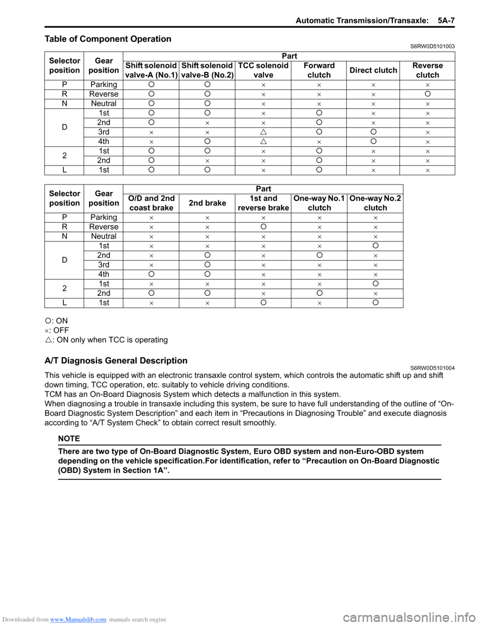
Table of Component OperationS6RW0D5101003
�{: ON
×: OFF
�U: ON only when TCC is operating
A/T Diagnosis General DescriptionS6RW0D5101004
This vehicle is equipped with an electronic transaxle control system, which controls the automatic shift up and shift
down timing, TCC operation, etc. suitably to vehicle driving conditions.
TCM has an On-Board Diagnosis System which detects a malfunction in this system.
When diagnosing a trouble in transaxle including this system, be sure to have full understanding of the outline of “On-
Board Diagnostic System Description” and each item in “Precautions in Diagnosing Trouble” and execute diagnosis
according to “A/T System Check” to obtain correct result smoothly.
NOTE
There are two type of On-Board Diagnostic System, Euro OBD system and non-Euro-OBD system
depending on the vehicle specification.For identification, refer to “Precaution on On-Board Diagnostic
(OBD) System in Section 1A”.
Selector
positionGear
positionPart
Shift solenoid
valve-A (No.1)Shift solenoid
valve-B (No.2)TCC solenoid
valveForward
clutchDirect clutchReverse
clutch
PParking�{�{× ×××
R Reverse�{�{×××�{
N Neutral�{�{× ×××
D1st�{�{×�{××
2nd�{××�{××
3rd××�U�{�{×
4th×�{�U×�{×
21st�{�{×�{××
2nd�{××�{××
L1st�{�{×�{××
Selector
positionGear
positionPart
O/D and 2nd
coast brake2nd brake1st and
reverse brakeOne-way No.1
clutchOne-way No.2
clutch
PParking×××××
R Reverse××�{××
N Neutral×××××
D1st××××�{
2nd×�{×�{×
3rd×�{×××
4th�{�{×××
21st××××�{
2nd�{�{×�{×
L1st××�{×�{
Page 658 of 1556
Downloaded from www.Manualslib.com manuals search engine 5A-10 Automatic Transmission/Transaxle:
Schematic and Routing Diagram
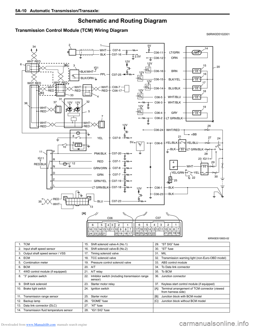
Transmission Control Module (TCM) Wiring DiagramS6RW0D5102001
12V
12V
12V
IG1
118
9
10
P
R
N
D
2
L12
2.5V
5V
12V
5V
12V
12V
12V
WHT
BLK
BLK
BLK
BLK
PPLBLK/WHT
BLK/ORN
IG11
RED/BLK
YEL/BLKYEL/BLU
LT GRN/BLK
+BB
WHT/RED
14
20 15
16
17
19
12V18
1 2
3
132126
24 27
28
29
30
65
16 15 14 13 12 1143
24 23 212210 9 8 721
19 20 18 17 C06
17 16
26 2515 14 65 342
13 12
23 22 2411 10 9
21 20 1987
18 1 C07
[A]
22
25
YELYEL/GRN
WHT
P
N
BRN LT/GRN
ORN
BLK/YEL
BLU/BLK
GRY
LT GRN/BLKWHT/BLU
WHT/BLK
C06-11
C06-12
C06-16
C06-15
C06-14
C06-4
C06-2
C06-1
C06-23C06-6 C06-24C06-5
C06-3
RED
GRN GRN/ORNPNK/BLK
GRN/YEL
LT GRN/BLKC07-6
C07-16
C07-23 C07-25
C07-20
C07-1
C07-8
C07-7
C07-19
C07-18
4IG11 23
C07-9
YEL
RED
WHTBLU35 34
3637
5REDWHT
7
WHT
RED
33
4
6
C06-7C06-17WHT
REDREDWHT
WHT
12V12V
WHTRED
WHTREDREDWHT
31
32
RED
WHTRED[B]
[C]
I6RW0D510003-02
1. TCM 15. Shift solenoid valve-A (No.1) 29. “ST SIG” fuse
2. Input shaft speed sensor 16. Shift solenoid valve-B (No.2) 30. “ST” fuse
3. Output shaft speed sensor / VSS 17. Timing solenoid valve 31. MIL
4. ECM 18. TCC solenoid valve 32. Transmission warning light (non-Euro-OBD model)
5. Combination meter 19. Pressure control solenoid valve 33. ABS control module
6. BCM 20. A/T 34. To Data link connector
7. 4WD control module (if equipped) 21. A/T relay 35. To BCM
8. “3” position switch 22. Inhibitor switch (including transmission range
sensor)36. Junction connector
9. Shift lock solenoid 23. Starter motor relay 37. Keyless start control module (if equipped)
10. Brake light switch 24. Ignition switch [A]: Terminal arrangement of TCM connector (viewed
from harness side)
11. Transmission range sensor 25. Starter motor [B]: Junction block with BCM model
12. Backup lamp 26. “DOME” fuse [C]: Junction block without BCM model
13. Data link connector (DLC) 27. “AT” fuse
14. Transmission fluid temperature sensor 28. “IG1 SIG” fuse