Timing SUZUKI SX4 2006 1.G Service Owner's Manual
[x] Cancel search | Manufacturer: SUZUKI, Model Year: 2006, Model line: SX4, Model: SUZUKI SX4 2006 1.GPages: 1556, PDF Size: 37.31 MB
Page 277 of 1556
Downloaded from www.Manualslib.com manuals search engine Engine Electrical Devices: 1C-9
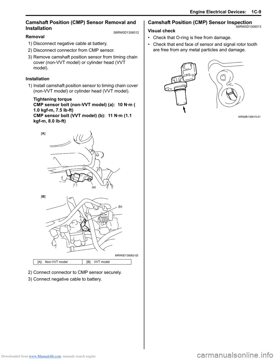
Camshaft Position (CMP) Sensor Removal and
Installation
S6RW0D1306012
Removal
1) Disconnect negative cable at battery.
2) Disconnect connector from CMP sensor.
3) Remove camshaft position sensor from timing chain
cover (non-VVT model) or cylinder head (VVT
model).
Installation
1) Install camshaft position sensor to timing chain cover
(non-VVT model) or cylinder head (VVT model).
Tightening torque
CMP sensor bolt (non-VVT model) (a): 10 N·m (
1.0 kgf-m, 7.5 lb-ft)
CMP sensor bolt (VVT model) (b): 11 N·m (1.1
kgf-m, 8.0 lb-ft)
2) Connect connector to CMP sensor securely.
3) Connect negative cable to battery.
Camshaft Position (CMP) Sensor InspectionS6RW0D1306013
Visual check
• Check that O-ring is free from damage.
• Check that end face of sensor and signal rotor tooth
are free from any metal particles and damage.
[A]: Non-VVT model [B]: VVT model
I6RW0D130002-02
I4RS0B130015-01
Page 283 of 1556
Downloaded from www.Manualslib.com manuals search engine Engine Mechanical: 1D-1
Engine
Engine Mechanical
General Description
Engine Construction DescriptionS6RW0D1401001
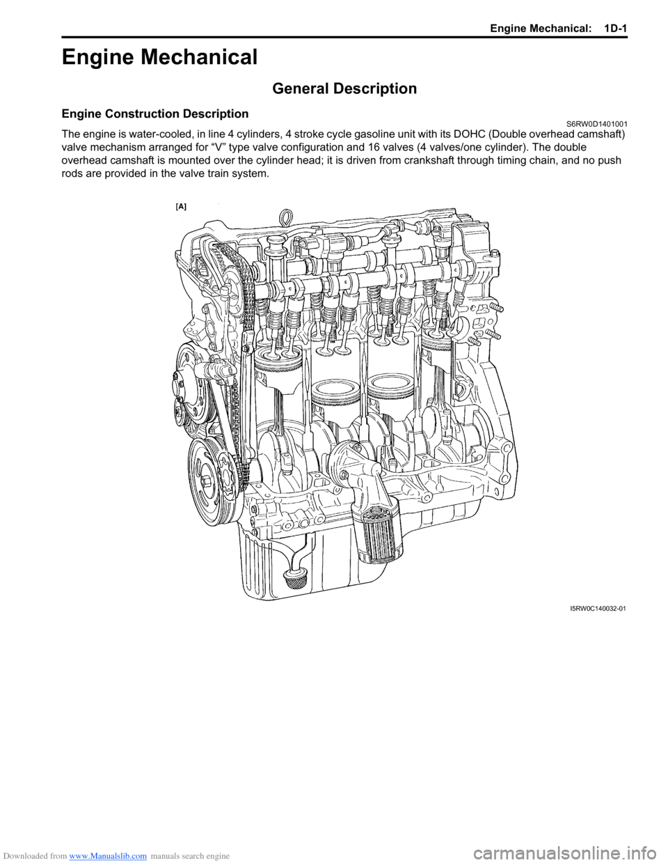
The engine is water-cooled, in line 4 cylinders, 4 stroke cycle gasoline unit with its DOHC (Double overhead camshaft)
valve mechanism arranged for “V” type valve configuration and 16 valves (4 valves/one cylinder). The double
overhead camshaft is mounted over the cylinder head; it is driven from crankshaft through timing chain, and no push
rods are provided in the valve train system.
I5RW0C140032-01
Page 285 of 1556
Downloaded from www.Manualslib.com manuals search engine Engine Mechanical: 1D-3
Camshaft Position Control (VVT Variable Valve Timing) System DescriptionS6RW0D1401002
System Description
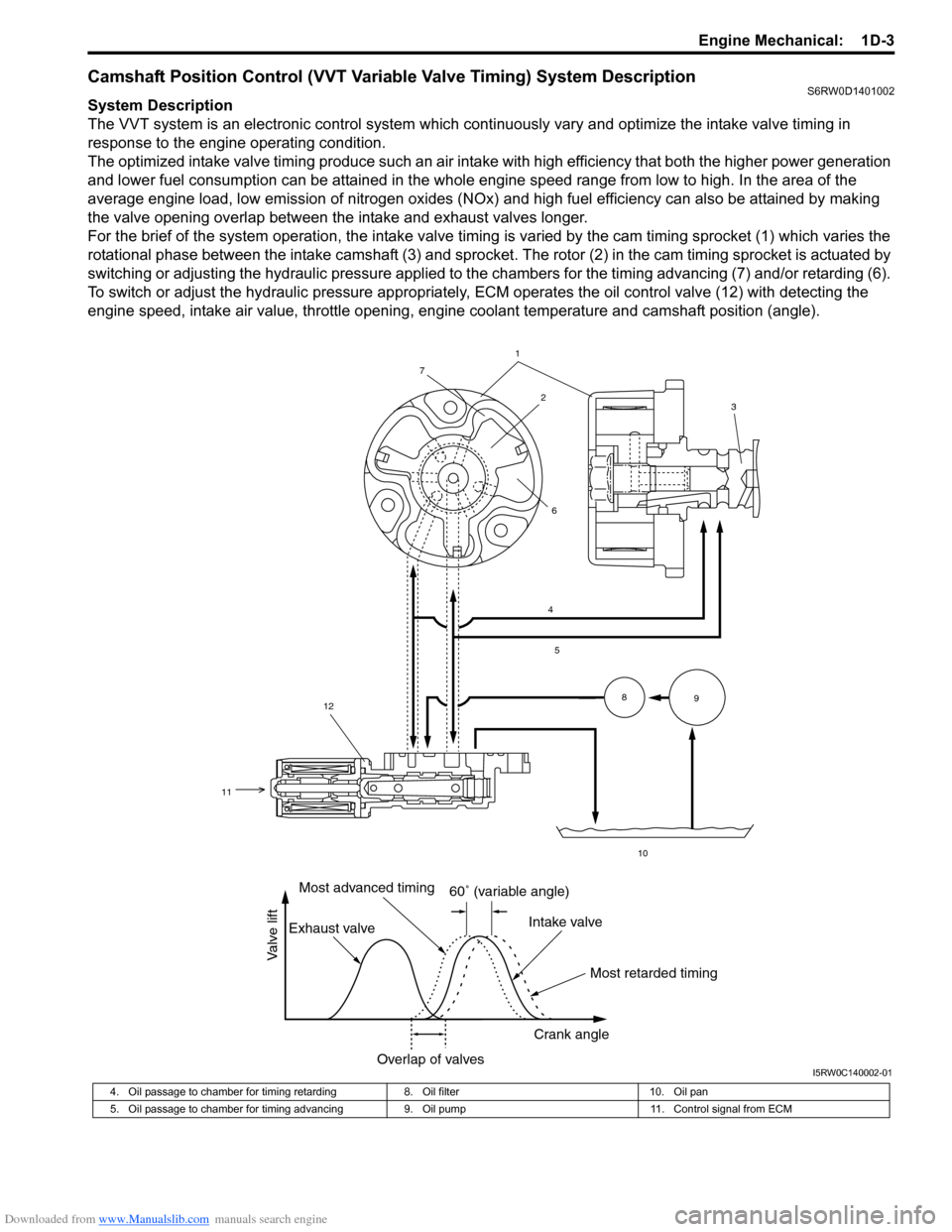
The VVT system is an electronic control system which continuously vary and optimize the intake valve timing in
response to the engine operating condition.
The optimized intake valve timing produce such an air intake with high efficiency that both the higher power generation
and lower fuel consumption can be attained in the whole engine speed range from low to high. In the area of the
average engine load, low emission of nitrogen oxides (NOx) and high fuel efficiency can also be attained by making
the valve opening overlap between the intake and exhaust valves longer.
For the brief of the system operation, the intake valve timing is varied by the cam timing sprocket (1) which varies the
rotational phase between the intake camshaft (3) and sprocket. The rotor (2) in the cam timing sprocket is actuated by
switching or adjusting the hydraulic pressure applied to the chambers for the timing advancing (7) and/or retarding (6).
To switch or adjust the hydraulic pressure appropriately, ECM operates the oil control valve (12) with detecting the
engine speed, intake air value, throttle opening, engine coolant temperature and camshaft position (angle).
1
4
5
10
8
9
2
7
6
12
11
3
60˚ (variable angle)
Most retarded timing Most advanced timing
Exhaust valveIntake valve
Crank angle
Overlap of valves
Valve lift
I5RW0C140002-01
4. Oil passage to chamber for timing retarding 8. Oil filter 10. Oil pan
5. Oil passage to chamber for timing advancing 9. Oil pump 11. Control signal from ECM
Page 286 of 1556
Downloaded from www.Manualslib.com manuals search engine 1D-4 Engine Mechanical:
Oil Control Valve
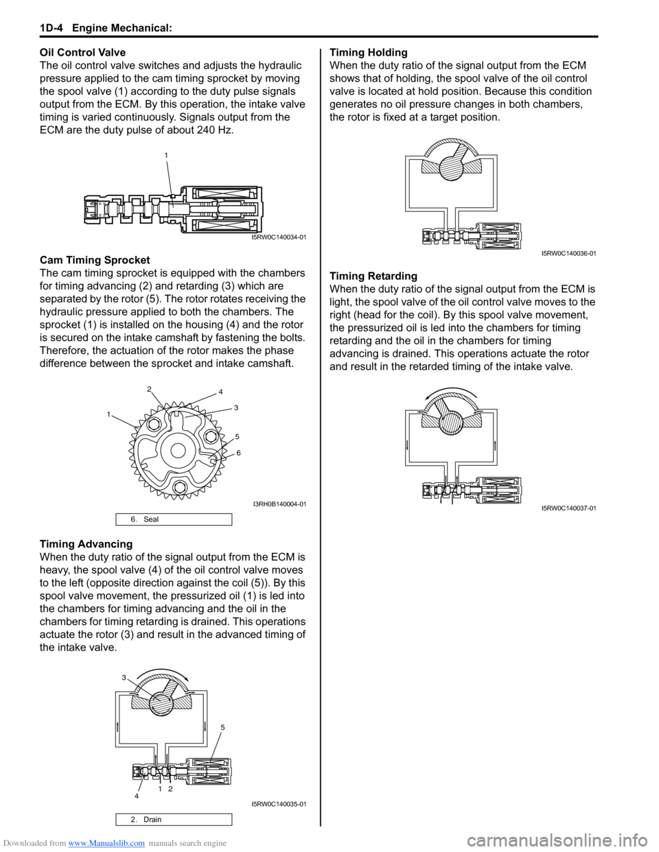
The oil control valve switches and adjusts the hydraulic
pressure applied to the cam timing sprocket by moving
the spool valve (1) according to the duty pulse signals
output from the ECM. By this operation, the intake valve
timing is varied continuously. Signals output from the
ECM are the duty pulse of about 240 Hz.
Cam Timing Sprocket
The cam timing sprocket is equipped with the chambers
for timing advancing (2) and retarding (3) which are
separated by the rotor (5). The rotor rotates receiving the
hydraulic pressure applied to both the chambers. The
sprocket (1) is installed on the housing (4) and the rotor
is secured on the intake camshaft by fastening the bolts.
Therefore, the actuation of the rotor makes the phase
difference between the sprocket and intake camshaft.
Timing Advancing
When the duty ratio of the signal output from the ECM is
heavy, the spool valve (4) of the oil control valve moves
to the left (opposite direction against the coil (5)). By this
spool valve movement, the pressurized oil (1) is led into
the chambers for timing advancing and the oil in the
chambers for timing retarding is drained. This operations
actuate the rotor (3) and result in the advanced timing of
the intake valve.Timing Holding
When the duty ratio of the signal output from the ECM
shows that of holding, the spool valve of the oil control
valve is located at hold position. Because this condition
generates no oil pressure changes in both chambers,
the rotor is fixed at a target position.
Timing Retarding
When the duty ratio of the signal output from the ECM is
light, the spool valve of the oil control valve moves to the
right (head for the coil). By this spool valve movement,
the pressurized oil is led into the chambers for timing
retarding and the oil in the chambers for timing
advancing is drained. This operations actuate the rotor
and result in the retarded timing of the intake valve.
6. Seal
2. Drain
1
I5RW0C140034-01
12
3 4
5
6
I3RH0B140004-01
1
2
5
4
3
I5RW0C140035-01
I5RW0C140036-01
I5RW0C140037-01
Page 287 of 1556
Downloaded from www.Manualslib.com manuals search engine Engine Mechanical: 1D-5
Targeted Timing Varying Operation
Diagnostic Information and Procedures
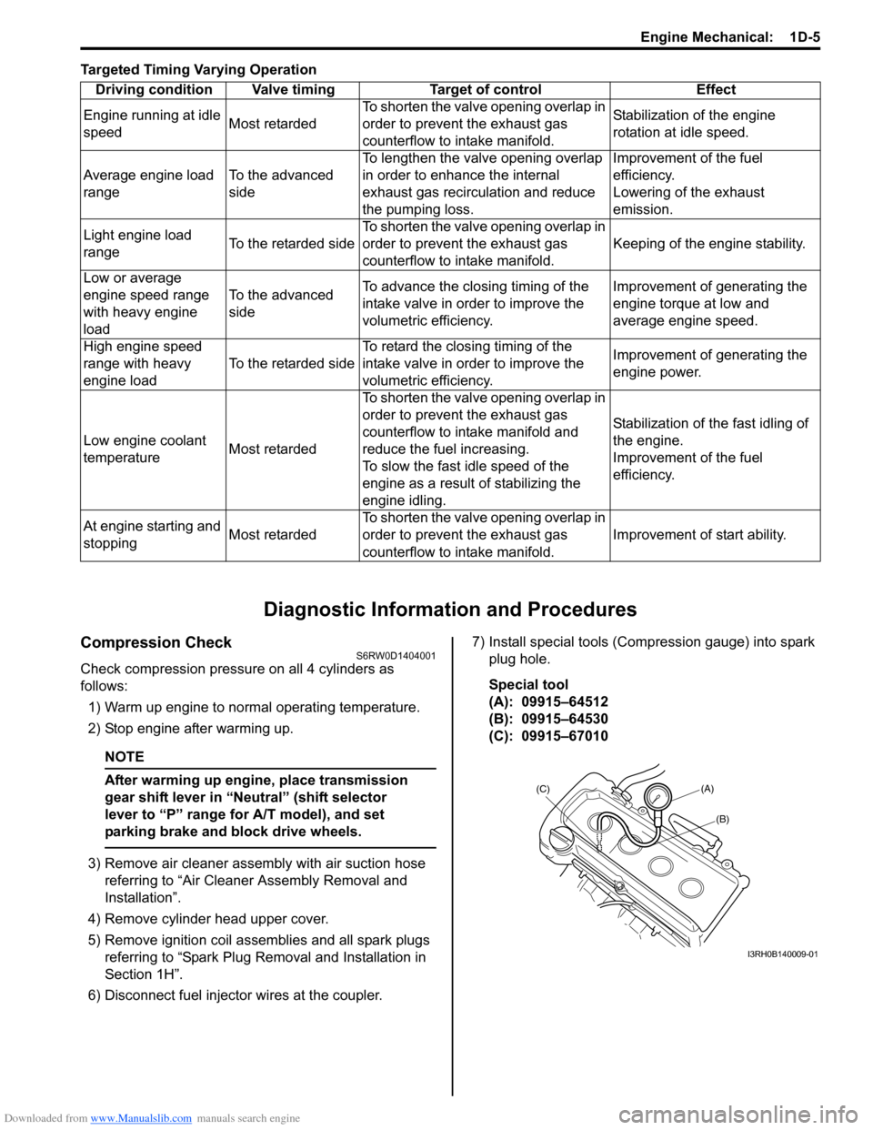
Compression CheckS6RW0D1404001
Check compression pressure on all 4 cylinders as
follows:
1) Warm up engine to normal operating temperature.
2) Stop engine after warming up.
NOTE
After warming up engine, place transmission
gear shift lever in “Neutral” (shift selector
lever to “P” range for A/T model), and set
parking brake and block drive wheels.
3) Remove air cleaner assembly with air suction hose
referring to “Air Cleaner Assembly Removal and
Installation”.
4) Remove cylinder head upper cover.
5) Remove ignition coil assemblies and all spark plugs
referring to “Spark Plug Removal and Installation in
Section 1H”.
6) Disconnect fuel injector wires at the coupler.7) Install special tools (Compression gauge) into spark
plug hole.
Special tool
(A): 09915–64512
(B): 09915–64530
(C): 09915–67010 Driving condition Valve timing Target of control Effect
Engine running at idle
speedMost retardedTo shorten the valve opening overlap in
order to prevent the exhaust gas
counterflow to intake manifold.Stabilization of the engine
rotation at idle speed.
Average engine load
rangeTo the advanced
sideTo lengthen the valve opening overlap
in order to enhance the internal
exhaust gas recirculation and reduce
the pumping loss.Improvement of the fuel
efficiency.
Lowering of the exhaust
emission.
Light engine load
rangeTo the retarded sideTo shorten the valve opening overlap in
order to prevent the exhaust gas
counterflow to intake manifold.Keeping of the engine stability.
Low or average
engine speed range
with heavy engine
loadTo the advanced
sideTo advance the closing timing of the
intake valve in order to improve the
volumetric efficiency.Improvement of generating the
engine torque at low and
average engine speed.
High engine speed
range with heavy
engine loadTo the retarded sideTo retard the closing timing of the
intake valve in order to improve the
volumetric efficiency.Improvement of generating the
engine power.
Low engine coolant
temperatureMost retardedTo shorten the valve opening overlap in
order to prevent the exhaust gas
counterflow to intake manifold and
reduce the fuel increasing.
To slow the fast idle speed of the
engine as a result of stabilizing the
engine idling.Stabilization of the fast idling of
the engine.
Improvement of the fuel
efficiency.
At engine starting and
stoppingMost retardedTo shorten the valve opening overlap in
order to prevent the exhaust gas
counterflow to intake manifold.Improvement of start ability.
(A)
(C)
(B)
I3RH0B140009-01
Page 290 of 1556
Downloaded from www.Manualslib.com manuals search engine 1D-8 Engine Mechanical:
2) Lift down the valve by turning crankshaft to 360°.
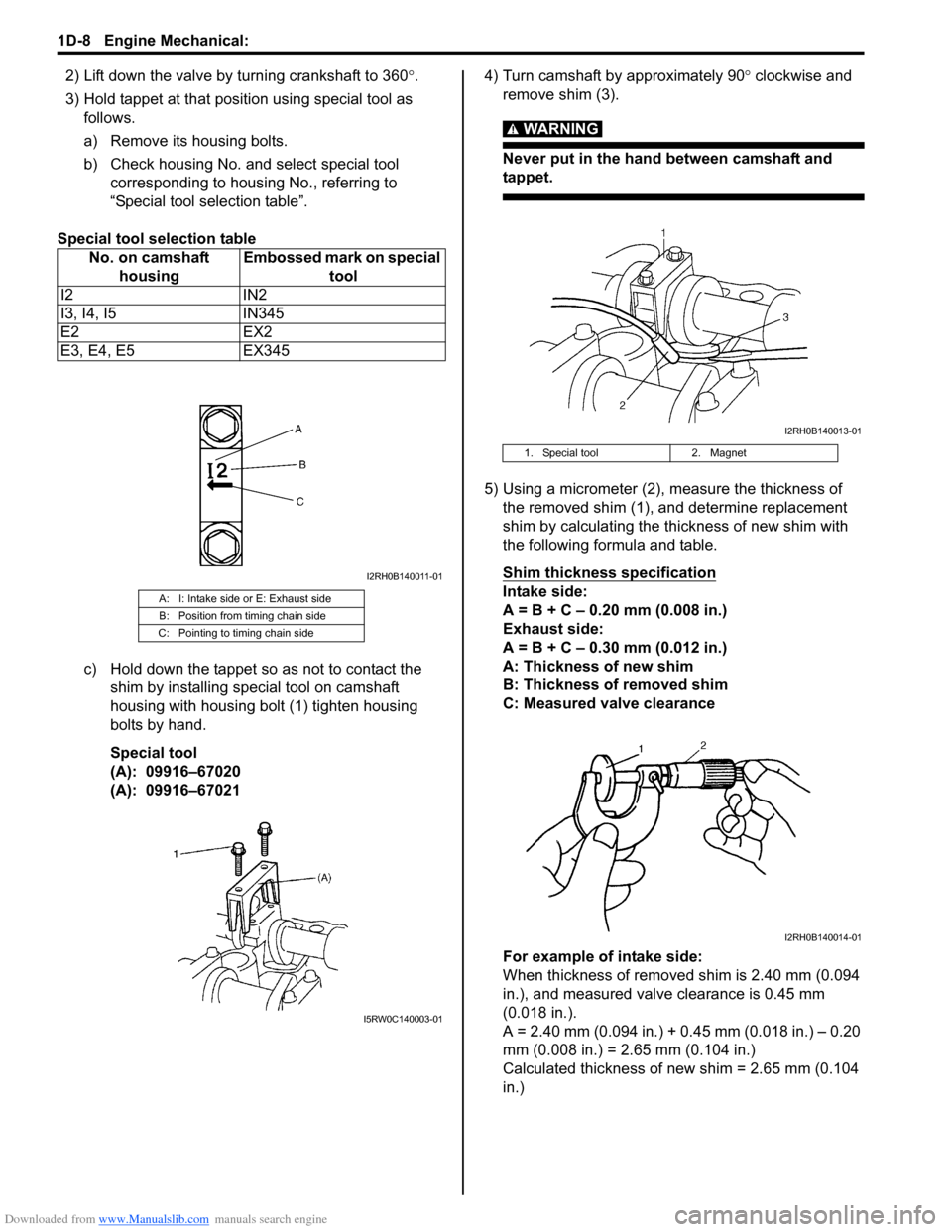
3) Hold tappet at that position using special tool as
follows.
a) Remove its housing bolts.
b) Check housing No. and select special tool
corresponding to housing No., referring to
“Special tool selection table”.
Special tool selection table
c) Hold down the tappet so as not to contact the
shim by installing special tool on camshaft
housing with housing bolt (1) tighten housing
bolts by hand.
Special tool
(A): 09916–67020
(A): 09916–670214) Turn camshaft by approximately 90° clockwise and
remove shim (3).
WARNING!
Never put in the hand between camshaft and
tappet.
5) Using a micrometer (2), measure the thickness of
the removed shim (1), and determine replacement
shim by calculating the thickness of new shim with
the following formula and table.
Shim thickness specification
Intake side:
A = B + C – 0.20 mm (0.008 in.)
Exhaust side:
A = B + C – 0.30 mm (0.012 in.)
A: Thickness of new shim
B: Thickness of removed shim
C: Measured valve clearance
For example of intake side:
When thickness of removed shim is 2.40 mm (0.094
in.), and measured valve clearance is 0.45 mm
(0.018 in.).
A = 2.40 mm (0.094 in.) + 0.45 mm (0.018 in.) – 0.20
mm (0.008 in.) = 2.65 mm (0.104 in.)
Calculated thickness of new shim = 2.65 mm (0.104
in.) No. on camshaft
housingEmbossed mark on special
tool
I2 IN2
I3, I4, I5 IN345
E2 EX2
E3, E4, E5 EX345A: I: Intake side or E: Exhaust side
B: Position from timing chain side
C: Pointing to timing chain side
I2RH0B140011-01
I5RW0C140003-01
1. Special tool 2. Magnet
I2RH0B140013-01
I2RH0B140014-01
Page 294 of 1556
Downloaded from www.Manualslib.com manuals search engine 1D-12 Engine Mechanical:
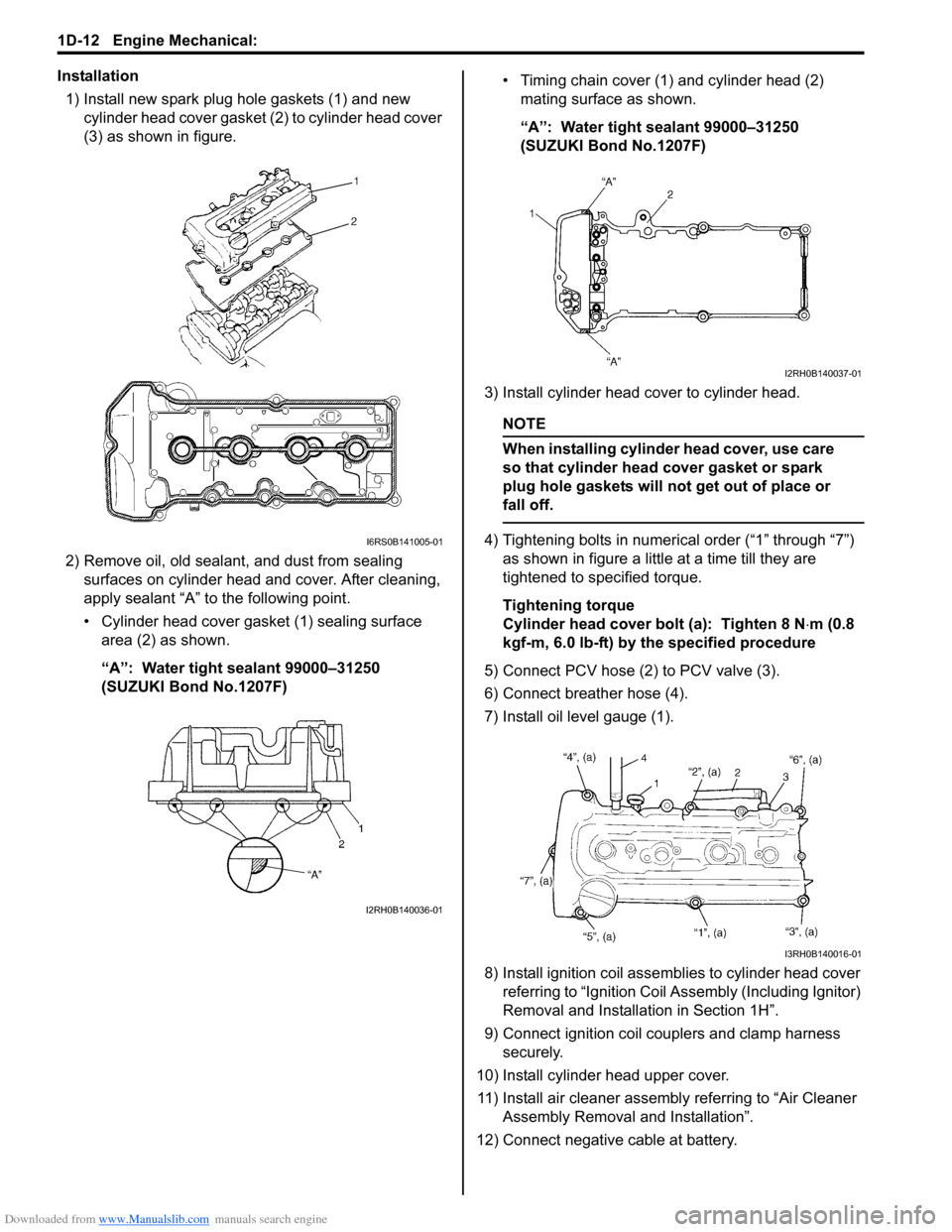
Installation
1) Install new spark plug hole gaskets (1) and new
cylinder head cover gasket (2) to cylinder head cover
(3) as shown in figure.
2) Remove oil, old sealant, and dust from sealing
surfaces on cylinder head and cover. After cleaning,
apply sealant “A” to the following point.
• Cylinder head cover gasket (1) sealing surface
area (2) as shown.
“A”: Water tight sealant 99000–31250
(SUZUKI Bond No.1207F)• Timing chain cover (1) and cylinder head (2)
mating surface as shown.
“A”: Water tight sealant 99000–31250
(SUZUKI Bond No.1207F)
3) Install cylinder head cover to cylinder head.
NOTE
When installing cylinder head cover, use care
so that cylinder head cover gasket or spark
plug hole gaskets will not get out of place or
fall off.
4) Tightening bolts in numerical order (“1” through “7”)
as shown in figure a little at a time till they are
tightened to specified torque.
Tightening torque
Cylinder head cover bolt (a): Tighten 8 N⋅m (0.8
kgf-m, 6.0 lb-ft) by the specified procedure
5) Connect PCV hose (2) to PCV valve (3).
6) Connect breather hose (4).
7) Install oil level gauge (1).
8) Install ignition coil assemblies to cylinder head cover
referring to “Ignition Coil Assembly (Including Ignitor)
Removal and Installation in Section 1H”.
9) Connect ignition coil couplers and clamp harness
securely.
10) Install cylinder head upper cover.
11) Install air cleaner assembly referring to “Air Cleaner
Assembly Removal and Installation”.
12) Connect negative cable at battery.I6RS0B141005-01
I2RH0B140036-01
I2RH0B140037-01
I3RH0B140016-01
Page 304 of 1556
![SUZUKI SX4 2006 1.G Service Owners Manual Downloaded from www.Manualslib.com manuals search engine 1D-22 Engine Mechanical:
Timing Chain Cover ComponentsS6RW0D1406014
I5RW0C140041-01
[A]: For engine with VVT 8. Timing chain cover mounting
n SUZUKI SX4 2006 1.G Service Owners Manual Downloaded from www.Manualslib.com manuals search engine 1D-22 Engine Mechanical:
Timing Chain Cover ComponentsS6RW0D1406014
I5RW0C140041-01
[A]: For engine with VVT 8. Timing chain cover mounting
n](/img/20/7612/w960_7612-303.png)
Downloaded from www.Manualslib.com manuals search engine 1D-22 Engine Mechanical:
Timing Chain Cover ComponentsS6RW0D1406014
I5RW0C140041-01
[A]: For engine with VVT 8. Timing chain cover mounting
nut17. Oil control valve
[B]: For engine without VVT 9. Oil gallery pipe No.1 18. Oil control valve mounting nut
1. Crankshaft pulley bolt 10. Copper washer 19. Cap
2. Crankshaft pulley 11. Oil gallery pipe No.1 bolt : 11 N⋅m (1.1 kgf-m, 8.0 lb-ft)
3. Oil seal
: Apply engine oil to oil seal lip.12. Oil gallery pipe No.2 : 25 N⋅m (2.5 kgf-m, 18.0 lb-ft)
4. Timing chain cover
: Apply sealant 99000-31140 to the mating
surface of cylinder and cylinder head.
: Apply sealant 99000-31260 to the mating
surface of timing chain cover referring to the
figure of Step 4) of “Installation” under “Timing
Chain Cover Removal and Installation”.13. Oil gallery pipe No.2 bolt : 30 N⋅m (3.0 kgf-m, 22.0 lb-ft)
5. Pin 14. Oil gallery pipe No.3 : 150 N⋅m (15.0 kgf-m, 108.5 lb-ft)
6. Cap bolt 15. Oil gallery pipe No.3 bolt : Do not reuse.
7. Timing chain cover mounting bolts 16. O-ring
: Apply engine oil.
Page 305 of 1556
Downloaded from www.Manualslib.com manuals search engine Engine Mechanical: 1D-23
Timing Chain Cover Removal and InstallationS6RW0D1406015
CAUTION!
• Keep working table, tools and hands clean
while overhauling.
• Use special care to handle aluminum parts
so as not to damage them.
• Do not expose removed parts to dust.
Keep them always clean.
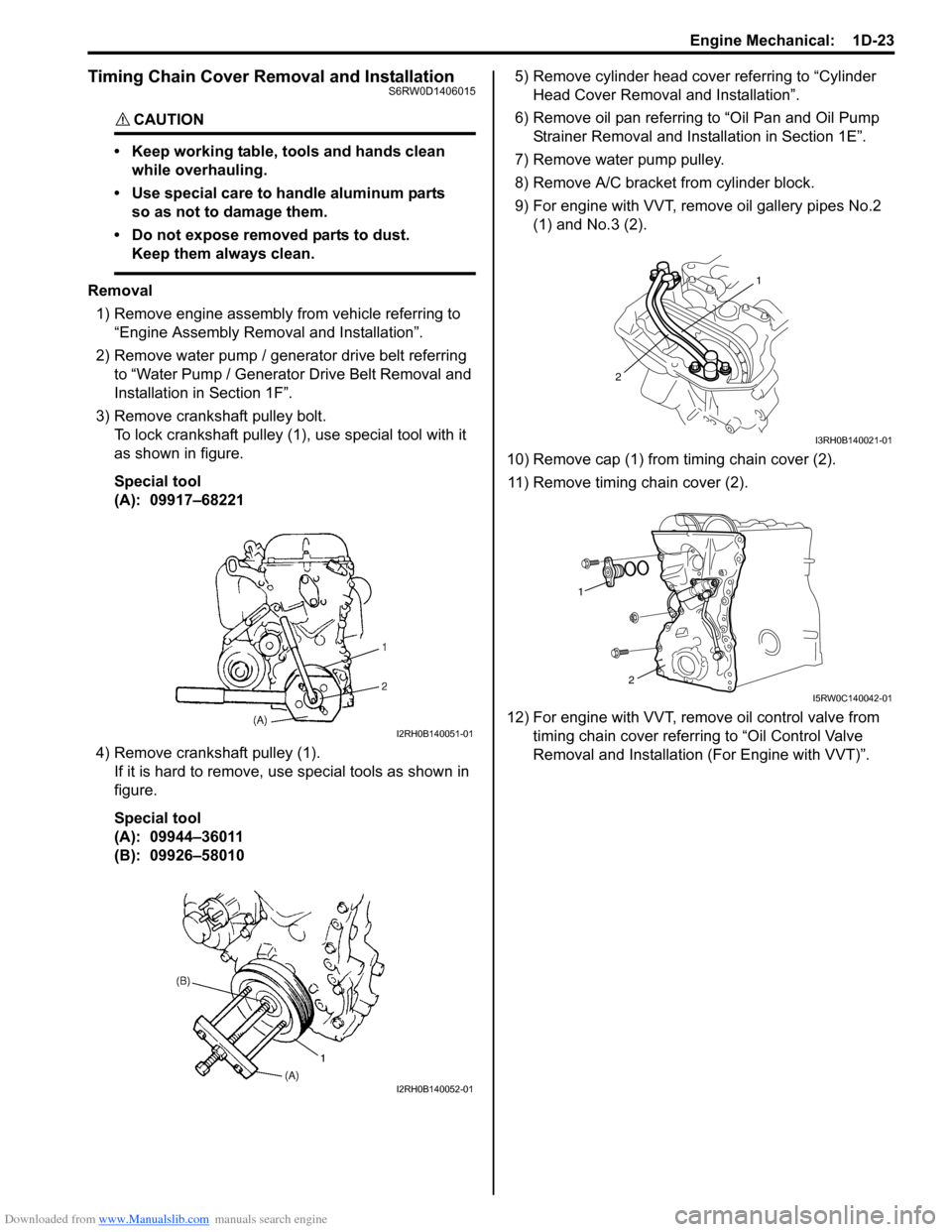
Removal
1) Remove engine assembly from vehicle referring to
“Engine Assembly Removal and Installation”.
2) Remove water pump / generator drive belt referring
to “Water Pump / Generator Drive Belt Removal and
Installation in Section 1F”.
3) Remove crankshaft pulley bolt.
To lock crankshaft pulley (1), use special tool with it
as shown in figure.
Special tool
(A): 09917–68221
4) Remove crankshaft pulley (1).
If it is hard to remove, use special tools as shown in
figure.
Special tool
(A): 09944–36011
(B): 09926–580105) Remove cylinder head cover referring to “Cylinder
Head Cover Removal and Installation”.
6) Remove oil pan referring to “Oil Pan and Oil Pump
Strainer Removal and Installation in Section 1E”.
7) Remove water pump pulley.
8) Remove A/C bracket from cylinder block.
9) For engine with VVT, remove oil gallery pipes No.2
(1) and No.3 (2).
10) Remove cap (1) from timing chain cover (2).
11) Remove timing chain cover (2).
12) For engine with VVT, remove oil control valve from
timing chain cover referring to “Oil Control Valve
Removal and Installation (For Engine with VVT)”.
I2RH0B140051-01
I2RH0B140052-01
1
2
I3RH0B140021-01
1
2
I5RW0C140042-01
Page 306 of 1556
Downloaded from www.Manualslib.com manuals search engine 1D-24 Engine Mechanical:
Installation
1) Clean sealing surface on timing chain cover, cylinder
block and cylinder head.
Remove oil, old sealant and dust from sealing
surface.
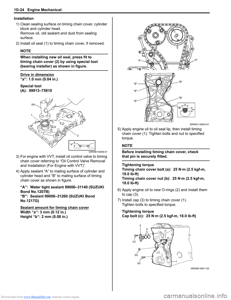
2) Install oil seal (1) to timing chain cover, if removed.
NOTE
When installing new oil seal, press fit to
timing chain cover (2) by using special tool
(bearing installer) as shown in figure.
Drive in dimension
“a”: 1.0 mm (0.04 in.)
Special tool
(A): 09913–75810
3) For engine with VVT, install oil control valve to timing
chain cover referring to “Oil Control Valve Removal
and Installation (For Engine with VVT)”.
4) Apply sealant “A” to mating surface of cylinder and
cylinder head and “B” to mating surface of timing
chain cover as shown in figure.
“A”: Water tight sealant 99000–31140 (SUZUKI
Bond No.1207B)
“B”: Sealant 99000–31260 (SUZUKI Bond
No.1217G)
Sealant amount for timing chain cover
Width “a”: 3 mm (0.12 in.)
Height “b”: 2 mm (0.08 in.)5) Apply engine oil to oil seal lip, then install timing
chain cover (1). Tighten bolts and nut to specified
torque.
NOTE
Before installing timing chain cover, check
that pin is securely fitted.
Tightening torque
Timing chain cover bolt (a): 25 N·m (2.5 kgf-m,
18.0 lb-ft)
Timing chain cover nut (b): 25 N·m (2.5 kgf-m,
18.0 lb-ft)
6) Apply engine oil to new O-rings (2) and install them
to cap (3).
7) Install cap (3) to timing chain cover (1).
Tighten bolts to specified torque.
Tightening torque
Cap bolt (c): 25 N·m (2.5 kgf-m, 18.0 lb-ft)
I2RH0B140058-01
I5RW0C140043-01
(a) (b) (c)
1 2 3
I4RS0B140011-02