esp SUZUKI SX4 2006 1.G Service Repair Manual
[x] Cancel search | Manufacturer: SUZUKI, Model Year: 2006, Model line: SX4, Model: SUZUKI SX4 2006 1.GPages: 1556, PDF Size: 37.31 MB
Page 813 of 1556
Downloaded from www.Manualslib.com manuals search engine Manual Transmission/Transaxle: 5B-1
Transmission / Transaxle
Manual Transmission/Transaxle
General Description
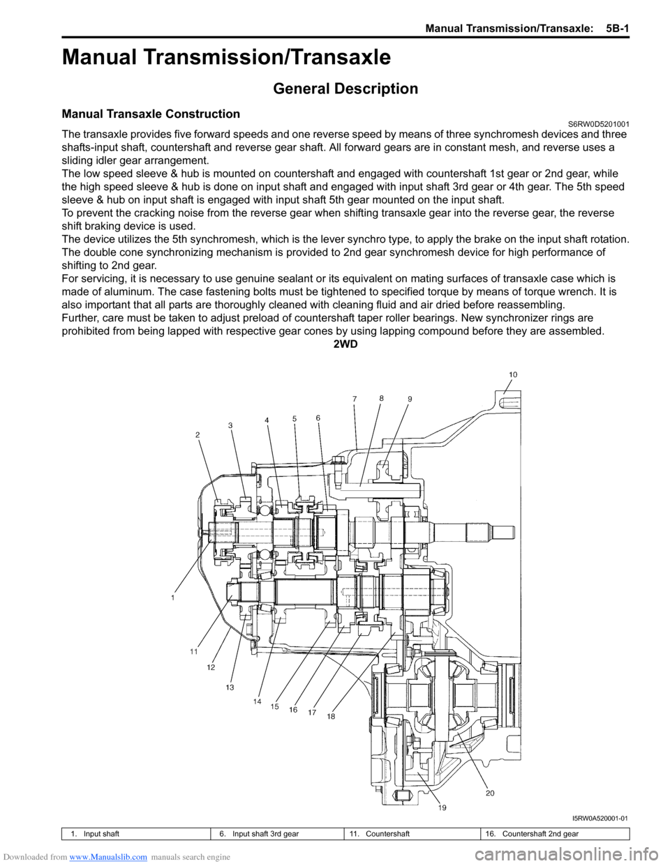
Manual Transaxle ConstructionS6RW0D5201001
The transaxle provides five forward speeds and one reverse speed by means of three synchromesh devices and three
shafts-input shaft, countershaft and reverse gear shaft. All forward gears are in constant mesh, and reverse uses a
sliding idler gear arrangement.
The low speed sleeve & hub is mounted on countershaft and engaged with countershaft 1st gear or 2nd gear, while
the high speed sleeve & hub is done on input shaft and engaged with input shaft 3rd gear or 4th gear. The 5th speed
sleeve & hub on input shaft is engaged with input shaft 5th gear mounted on the input shaft.
To prevent the cracking noise from the reverse gear when shifting transaxle gear into the reverse gear, the reverse
shift braking device is used.
The device utilizes the 5th synchromesh, which is the lever synchro type, to apply the brake on the input shaft rotation.
The double cone synchronizing mechanism is provided to 2nd gear synchromesh device for high performance of
shifting to 2nd gear.
For servicing, it is necessary to use genuine sealant or its equivalent on mating surfaces of transaxle case which is
made of aluminum. The case fastening bolts must be tightened to specified torque by means of torque wrench. It is
also important that all parts are thoroughly cleaned with cleaning fluid and air dried before reassembling.
Further, care must be taken to adjust preload of countershaft taper roller bearings. New synchronizer rings are
prohibited from being lapped with respective gear cones by using lapping compound before they are assembled.
2WD
I5RW0A520001-01
1. Input shaft 6. Input shaft 3rd gear 11. Countershaft 16. Countershaft 2nd gear
Page 834 of 1556

Downloaded from www.Manualslib.com manuals search engine 5B-22 Manual Transmission/Transaxle:
6) Clean mating surfaces of both right and left cases,
apply sealant to left case (2) as shown in the figure
by such amount that its section is 1.5 mm (0.059 in.)
in diameter then mate it with right case (1).
“A”: Sealant 99000–31260 (SUZUKI Bond
No.1217G)
7) Tighten case bolts (3) from outside and tighten
another case bolts from clutch housing side to
specified torque.
Tightening torque
Transaxle case bolt (a): 23 N·m (2.3 kgf-m, 17.0
lb-ft)
8) Install reverse shaft bolt (4) to which thread lock
cement has been applied, with aluminum washer
and tighten it to specified torque.
“B”: Sealant 99000–31260 (SUZUKI Bond
No.1217G)
Tightening torque
Reverse shaft bolt (b): 23 N·m (2.3 kgf-m, 17.0
lb-ft)9) Check locating springs (2, 4 and 5) for deterioration
and replace with new ones as necessary.
Locating spring
10) Install steel balls (3) and locating springs (2, 4 and 5)
for respective gear shift shaft and tighten bolts (1) to
which thread lock cement has been applied.
“A”: Thread lock cement 99000–32110 (Thread
Lock Cement Super 1322)
Tightening torque
Gear shift locating bolt (a): 13 N·m (1.3 kgf-m,
9.5 lb-ft)
11) Install new snap ring (1) using special tool.
Special tool
(A): 09900–06107
I5RW0A520023-01
Locating spring free length Standard Service limit
Low speed (2)53.1 mm
(2.091 in.)47.8 mm
(1.881 in.)
High speed (4)45.9 mm
(1.807 in.)41.4 mm
(1.629 in.)
5th & reverse (5)29.9 mm
(1.777 in.)27.0 mm
(1.062 in.)
2. Input shaft
3. Input shaft left bearing
1, (a), “A”
2
3
4
5
I5RW0A520024-02
1 (A)
2
3
I3RH0A520016-01
Page 873 of 1556
Downloaded from www.Manualslib.com manuals search engine Steering Wheel and Column: 6B-4
Steering Wheel Removal and InstallationS6RW0D6206002
CAUTION!
Do not turn the contact coil more than
allowable number of turns (about two and a
half turns from the center position clockwise
or counterclockwise respectively) with
steering wheel removed, or coil will break.
Removal
CAUTION!
Do not hammer the end of the shaft.
Hammering it will loosen the plastic shear
pins which maintain the column length and
impair the collapsible design of the column.
1) Disconnect negative (–) cable at battery.
2) Disable air bag system referring to “Disabling Air
Bag System in Section 8B”.
3) Remove driver air bag (inflator) module from
steering wheel. Refer to “Driver Air Bag (Inflator)
Module Removal and Installation in Section 8B”.
4) Disconnect horn connector and audio control switch
connector, if equipped.
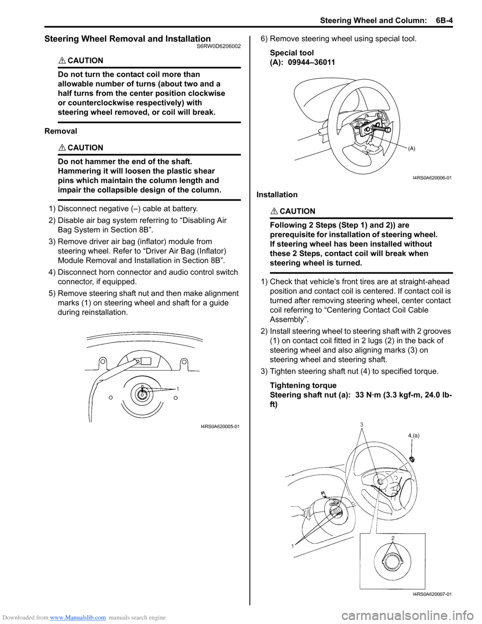
5) Remove steering shaft nut and then make alignment
marks (1) on steering wheel and shaft for a guide
during reinstallation.6) Remove steering wheel using special tool.
Special tool
(A): 09944–36011
InstallationCAUTION!
Following 2 Steps (Step 1) and 2)) are
prerequisite for installation of steering wheel.
If steering wheel has been installed without
these 2 Steps, contact coil will break when
steering wheel is turned.
1) Check that vehicle’s front tires are at straight-ahead
position and contact coil is centered. If contact coil is
turned after removing steering wheel, center contact
coil referring to “Centering Contact Coil Cable
Assembly”.
2) Install steering wheel to steering shaft with 2 grooves
(1) on contact coil fitted in 2 lugs (2) in the back of
steering wheel and also aligning marks (3) on
steering wheel and steering shaft.
3) Tighten steering shaft nut (4) to specified torque.
Tightening torque
Steering shaft nut (a): 33 N·m (3.3 kgf-m, 24.0 lb-
ft)
I4RS0A620005-01
(A)
I4RS0A620006-01
I4RS0A620007-01
Page 874 of 1556
Downloaded from www.Manualslib.com manuals search engine 6B-5 Steering Wheel and Column:
4) Connect horn connector and audio control switch
connector, if necessary.
5) Install driver air bag (inflator) module to steering
wheel. Refer to “Driver Air Bag (Inflator) Module
Removal and Installation in Section 8B”.
6) Connect negative (–) cable to battery.
7) Enable air bag system referring to “Enabling Air Bag
System in Section 8B”.
Contact Coil Cable Assembly Removal and
Installation
S6RW0D6206003
CAUTION!
Do not turn contact coil more than allowable
number of turns (about two and a half turns
from the center position clockwise or
counterclockwise respectively), or coil will
break.
Removal
1) Disconnect negative (–) cable at battery.
2) Disable air bag system referring to “Disabling Air
Bag System in Section 8B”.
3) Remove steering wheel from steering column
referring to “Steering Wheel Removal and
Installation”.
4) Remove steering column hole cover.
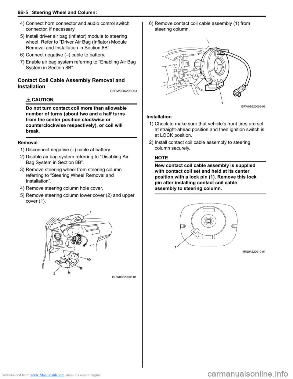
5) Remove steering column lower cover (2) and upper
cover (1).6) Remove contact coil cable assembly (1) from
steering column.
Installation
1) Check to make sure that vehicle’s front tires are set
at straight-ahead position and then ignition switch is
at LOCK position.
2) Install contact coil cable assembly to steering
column securely.
NOTE
New contact coil cable assembly is supplied
with contact coil set and held at its center
position with a lock pin (1). Remove this lock
pin after installing contact coil cable
assembly to steering column.
2
1
I6RW0B620005-01
1I6RW0B620009-02
I4RS0A620010-01
Page 889 of 1556
Downloaded from www.Manualslib.com manuals search engine Power Assisted Steering System: 6C-9
DTC ClearanceS6RW0D6304004
1) Turn ignition switch to OFF position.
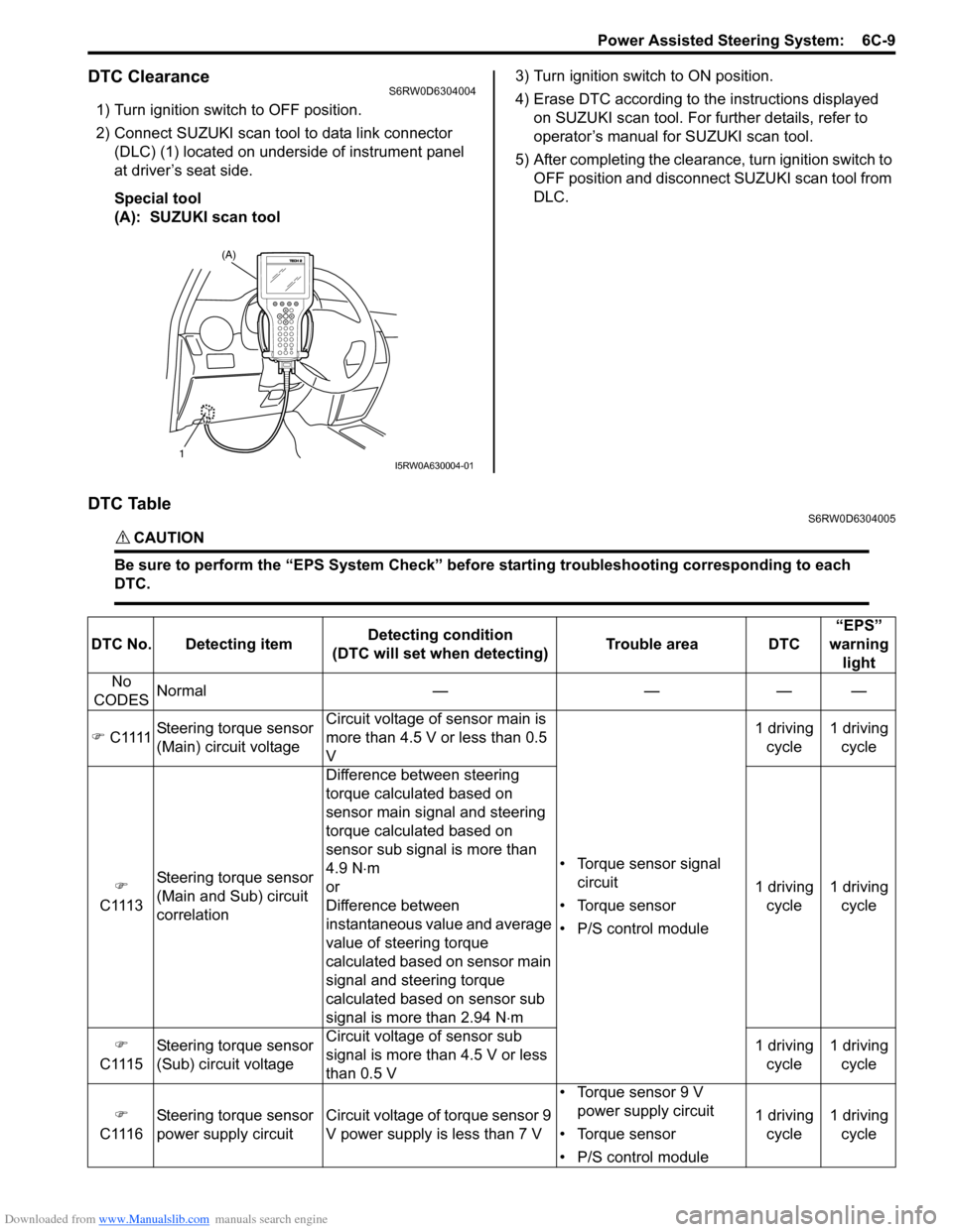
2) Connect SUZUKI scan tool to data link connector
(DLC) (1) located on underside of instrument panel
at driver’s seat side.
Special tool
(A): SUZUKI scan tool3) Turn ignition switch to ON position.
4) Erase DTC according to the instructions displayed
on SUZUKI scan tool. For further details, refer to
operator’s manual for SUZUKI scan tool.
5) After completing the clearance, turn ignition switch to
OFF position and disconnect SUZUKI scan tool from
DLC.
DTC TableS6RW0D6304005
CAUTION!
Be sure to perform the “EPS System Check” before starting troubleshooting corresponding to each
DTC.
(A)
1I5RW0A630004-01
DTC No. Detecting itemDetecting condition
(DTC will set when detecting)Trouble area DTC“EPS”
warning
light
No
CODESNormal — — — —
�) C1111Steering torque sensor
(Main) circuit voltageCircuit voltage of sensor main is
more than 4.5 V or less than 0.5
V
• Torque sensor signal
circuit
• Torque sensor
• P/S control module1 driving
cycle1 driving
cycle
�)
C1113Steering torque sensor
(Main and Sub) circuit
correlationDifference between steering
torque calculated based on
sensor main signal and steering
torque calculated based on
sensor sub signal is more than
4.9 N⋅m
or
Difference between
instantaneous value and average
value of steering torque
calculated based on sensor main
signal and steering torque
calculated based on sensor sub
signal is more than 2.94 N⋅m1 driving
cycle1 driving
cycle
�)
C1115Steering torque sensor
(Sub) circuit voltageCircuit voltage of sensor sub
signal is more than 4.5 V or less
than 0.5 V1 driving
cycle1 driving
cycle
�)
C1116Steering torque sensor
power supply circuit Circuit voltage of torque sensor 9
V power supply is less than 7 V• Torque sensor 9 V
power supply circuit
• Torque sensor
• P/S control module1 driving
cycle1 driving
cycle
Page 948 of 1556
Downloaded from www.Manualslib.com manuals search engine 7B-8 Air Conditioning System: Manual Type
Diagnostic Information and Procedures
A/C System Performance InspectionS6RW0D7214001
1) Confirm that vehicle and environmental conditions
are as follows.
• Vehicle is put indoors.
• Ambient temperature is within 25 – 35 °C (77 – 95
°F).
• Relative humidity is within 30 – 70%.
• There is no wind indoors.
• HVAC unit is normal.
• Blower motor is normal.
• There is no air leakage from air ducts.
• Condenser fins are clean.
• HVAC air filter is not clogged with dirt and dust (if
equipped).
• Battery voltage is about 12 V.
• Radiator cooling fan operates normally.
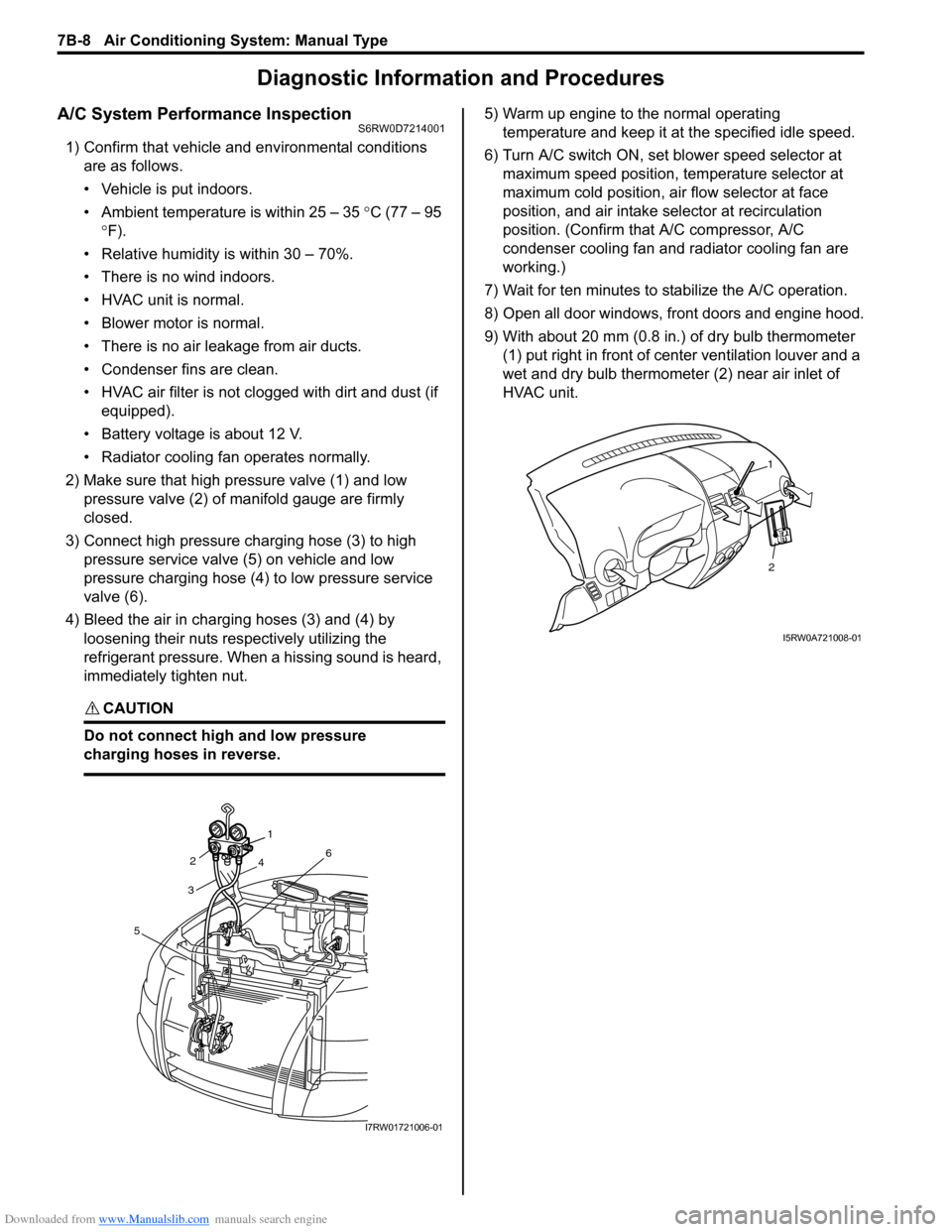
2) Make sure that high pressure valve (1) and low
pressure valve (2) of manifold gauge are firmly
closed.
3) Connect high pressure charging hose (3) to high
pressure service valve (5) on vehicle and low
pressure charging hose (4) to low pressure service
valve (6).
4) Bleed the air in charging hoses (3) and (4) by
loosening their nuts respectively utilizing the
refrigerant pressure. When a hissing sound is heard,
immediately tighten nut.
CAUTION!
Do not connect high and low pressure
charging hoses in reverse.
5) Warm up engine to the normal operating
temperature and keep it at the specified idle speed.
6) Turn A/C switch ON, set blower speed selector at
maximum speed position, temperature selector at
maximum cold position, air flow selector at face
position, and air intake selector at recirculation
position. (Confirm that A/C compressor, A/C
condenser cooling fan and radiator cooling fan are
working.)
7) Wait for ten minutes to stabilize the A/C operation.
8) Open all door windows, front doors and engine hood.
9) With about 20 mm (0.8 in.) of dry bulb thermometer
(1) put right in front of center ventilation louver and a
wet and dry bulb thermometer (2) near air inlet of
HVAC unit.
321
4
6
5
I7RW01721006-01
2
1
I5RW0A721008-01
Page 959 of 1556
Downloaded from www.Manualslib.com manuals search engine Air Conditioning System: Manual Type 7B-19
Evacuation
CAUTION!
Do not evacuate before recovering
refrigerant in A/C system.
NOTE
Once air conditioning system circuit is
opened (exposed) to atmospheric air, system
must be evacuated by using a vacuum pump.
The A/C system should be attached with a
manifold gauge set, and should be evacuated
for approximately 15 minutes.
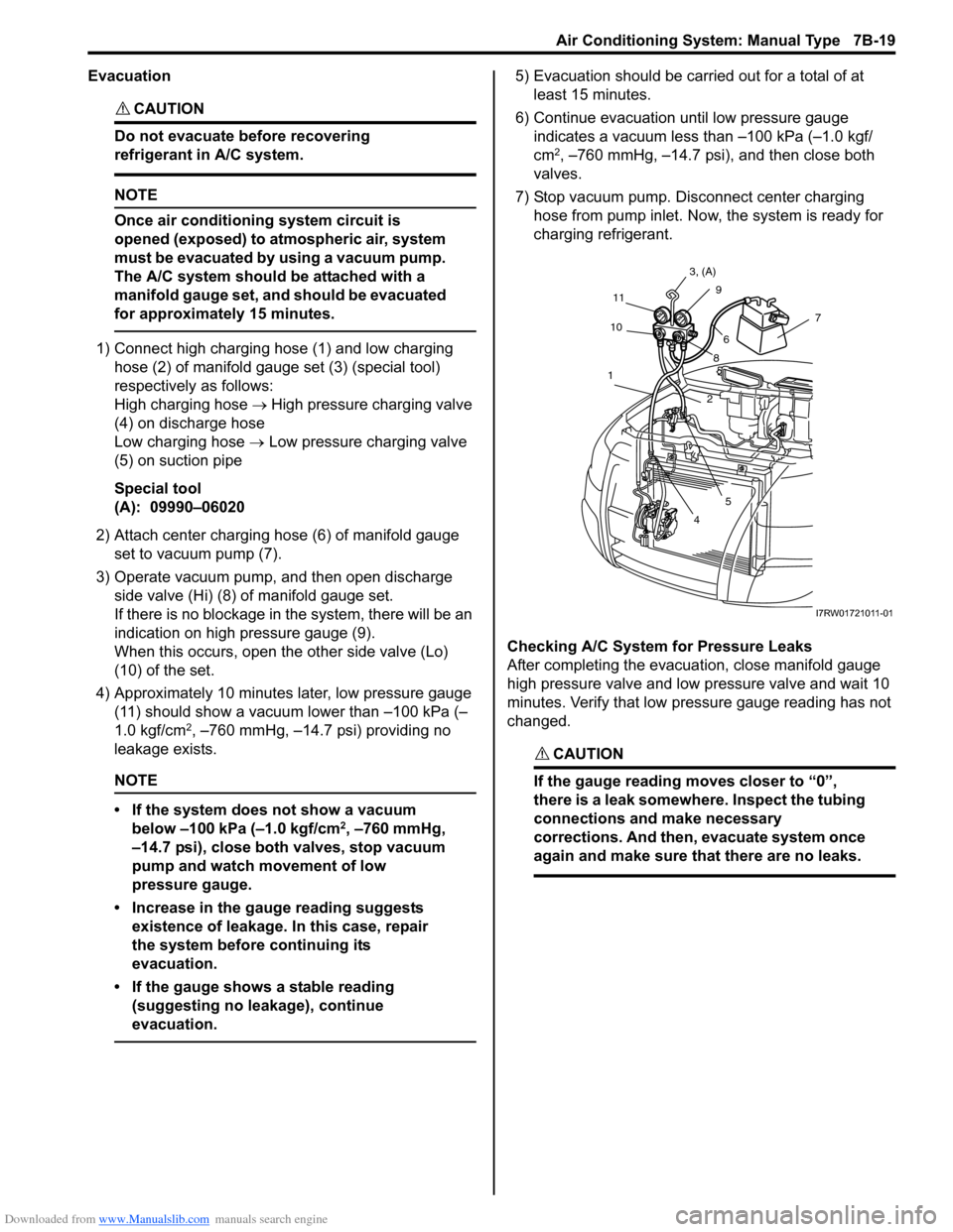
1) Connect high charging hose (1) and low charging
hose (2) of manifold gauge set (3) (special tool)
respectively as follows:
High charging hose → High pressure charging valve
(4) on discharge hose
Low charging hose → Low pressure charging valve
(5) on suction pipe
Special tool
(A): 09990–06020
2) Attach center charging hose (6) of manifold gauge
set to vacuum pump (7).
3) Operate vacuum pump, and then open discharge
side valve (Hi) (8) of manifold gauge set.
If there is no blockage in the system, there will be an
indication on high pressure gauge (9).
When this occurs, open the other side valve (Lo)
(10) of the set.
4) Approximately 10 minutes later, low pressure gauge
(11) should show a vacuum lower than –100 kPa (–
1.0 kgf/cm
2, –760 mmHg, –14.7 psi) providing no
leakage exists.
NOTE
• If the system does not show a vacuum
below –100 kPa (–1.0 kgf/cm
2, –760 mmHg,
–14.7 psi), close both valves, stop vacuum
pump and watch movement of low
pressure gauge.
• Increase in the gauge reading suggests
existence of leakage. In this case, repair
the system before continuing its
evacuation.
• If the gauge shows a stable reading
(suggesting no leakage), continue
evacuation.
5) Evacuation should be carried out for a total of at
least 15 minutes.
6) Continue evacuation until low pressure gauge
indicates a vacuum less than –100 kPa (–1.0 kgf/
cm
2, –760 mmHg, –14.7 psi), and then close both
valves.
7) Stop vacuum pump. Disconnect center charging
hose from pump inlet. Now, the system is ready for
charging refrigerant.
Checking A/C System for Pressure Leaks
After completing the evacuation, close manifold gauge
high pressure valve and low pressure valve and wait 10
minutes. Verify that low pressure gauge reading has not
changed.
CAUTION!
If the gauge reading moves closer to “0”,
there is a leak somewhere. Inspect the tubing
connections and make necessary
corrections. And then, evacuate system once
again and make sure that there are no leaks.
7
89 3, (A)
11
10
1
2
5
4
6
I7RW01721011-01
Page 961 of 1556
Downloaded from www.Manualslib.com manuals search engine Air Conditioning System: Manual Type 7B-21
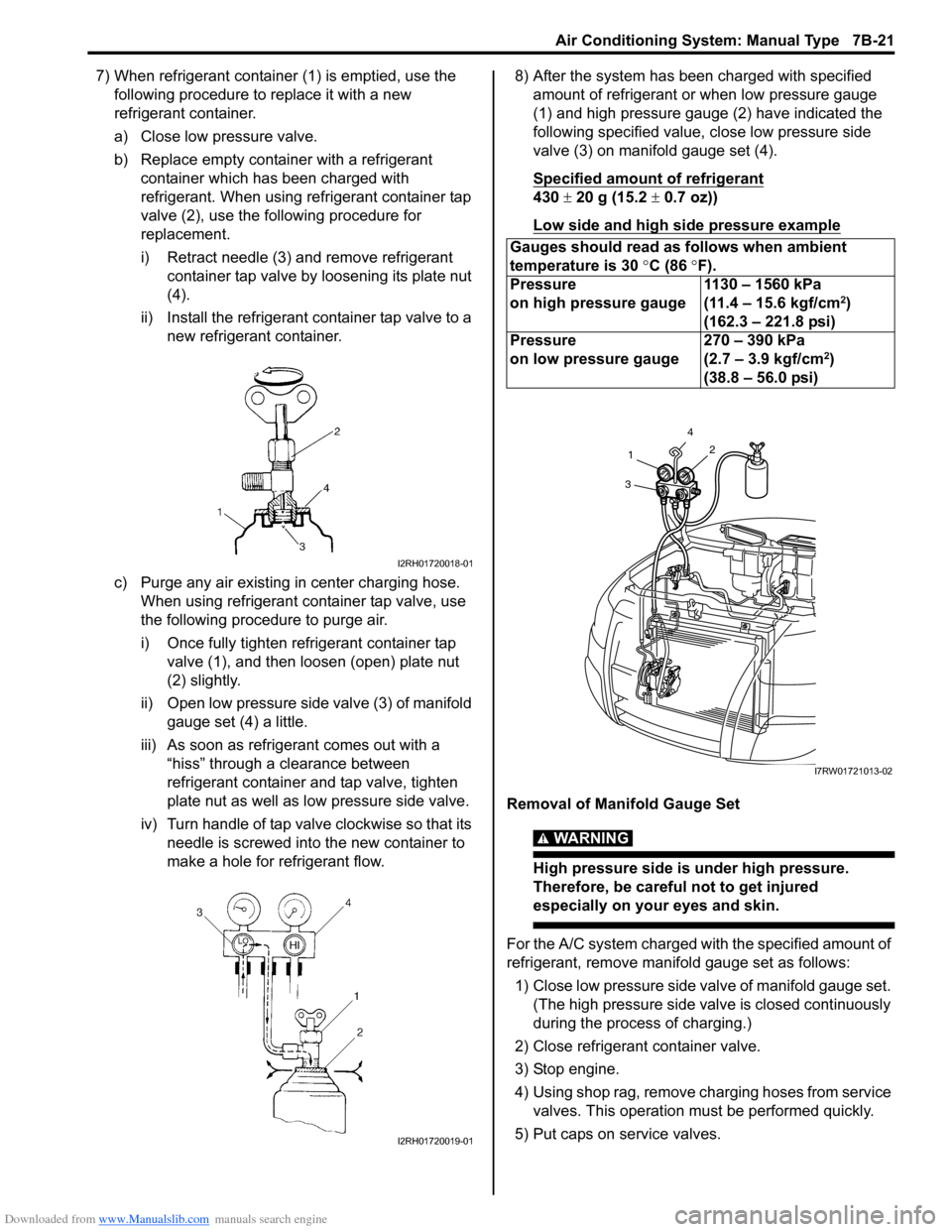
7) When refrigerant container (1) is emptied, use the
following procedure to replace it with a new
refrigerant container.
a) Close low pressure valve.
b) Replace empty container with a refrigerant
container which has been charged with
refrigerant. When using refrigerant container tap
valve (2), use the following procedure for
replacement.
i) Retract needle (3) and remove refrigerant
container tap valve by loosening its plate nut
(4).
ii) Install the refrigerant container tap valve to a
new refrigerant container.
c) Purge any air existing in center charging hose.
When using refrigerant container tap valve, use
the following procedure to purge air.
i) Once fully tighten refrigerant container tap
valve (1), and then loosen (open) plate nut
(2) slightly.
ii) Open low pressure side valve (3) of manifold
gauge set (4) a little.
iii) As soon as refrigerant comes out with a
“hiss” through a clearance between
refrigerant container and tap valve, tighten
plate nut as well as low pressure side valve.
iv) Turn handle of tap valve clockwise so that its
needle is screwed into the new container to
make a hole for refrigerant flow.8) After the system has been charged with specified
amount of refrigerant or when low pressure gauge
(1) and high pressure gauge (2) have indicated the
following specified value, close low pressure side
valve (3) on manifold gauge set (4).
Specified amount of refrigerant
430 ± 20 g (15.2 ± 0.7 oz))
Low side and high side pressure example
Removal of Manifold Gauge Set
WARNING!
High pressure side is under high pressure.
Therefore, be careful not to get injured
especially on your eyes and skin.
For the A/C system charged with the specified amount of
refrigerant, remove manifold gauge set as follows:
1) Close low pressure side valve of manifold gauge set.
(The high pressure side valve is closed continuously
during the process of charging.)
2) Close refrigerant container valve.
3) Stop engine.
4) Using shop rag, remove charging hoses from service
valves. This operation must be performed quickly.
5) Put caps on service valves.
I2RH01720018-01
I2RH01720019-01
Gauges should read as follows when ambient
temperature is 30 °C (86 °F).
Pressure
on high pressure gauge1130 – 1560 kPa
(11.4 – 15.6 kgf/cm
2)
(162.3 – 221.8 psi)
Pressure
on low pressure gauge270 – 390 kPa
(2.7 – 3.9 kgf/cm
2)
(38.8 – 56.0 psi)
4
2
1
3
I7RW01721013-02
Page 972 of 1556
Downloaded from www.Manualslib.com manuals search engine 7B-32 Air Conditioning System: Manual Type
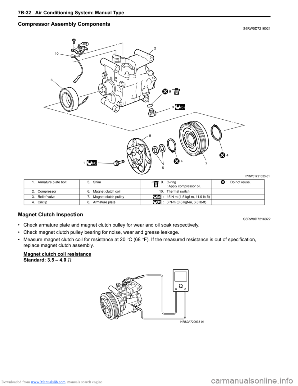
Compressor Assembly ComponentsS6RW0D7216021
Magnet Clutch InspectionS6RW0D7216022
• Check armature plate and magnet clutch pulley for wear and oil soak respectively.
• Check magnet clutch pulley bearing for noise, wear and grease leakage.
• Measure magnet clutch coil for resistance at 20 °C (68 °F). If the measured resistance is out of specification,
replace magnet clutch assembly.
Magnet clutch coil resistance
Standard: 3.5 – 4.0 Ω
6
2
9
4
4 3
1
7
5 8(a)
(b)
10
I7RW01721023-01
1. Armature plate bolt 5. Shim 9. O-ring
: Apply compressor oil.: Do not reuse.
2. Compressor 6. Magnet clutch coil 10. Thermal switch
3. Relief valve 7. Magnet clutch pulley : 15 N⋅m (1.5 kgf-m, 11.0 lb-ft)
4. Circlip 8. Armature plate : 8 N⋅m (0.8 kgf-m, 6.0 lb-ft)
I4RS0A720038-01
Page 979 of 1556
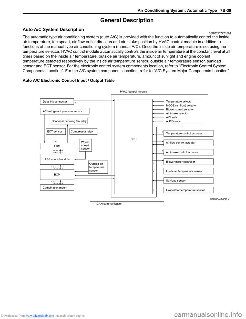
Downloaded from www.Manualslib.com manuals search engine Air Conditioning System: Automatic Type 7B-39
General Description
Auto A/C System DescriptionS6RW0D7221001
The automatic type air conditioning system (auto A/C) is provided with the function to automatically control the inside
air temperature, fan speed, air flow outlet direction and air intake position by HVAC control module in addition to
functions of the manual type air conditioning system (manual A/C). Once the inside air temperature is set using the
temperature selector, HVAC control module automatically controls the inside air temperature at the constant level at all
times based on the inside air temperature, outside air temperature, amount of sunlight and engine coolant
temperature detected respectively by the inside air temperature sensor, outside air temperature sensor, sunload
sensor and ECT sensor. For the electronic control system components location, refer to “Electronic Control System
Components Location”. For the A/C system components location, refer to “A/C System Major Components Location”.
Auto A/C Electronic Control Input / Output Table
Temperature selector
MODE (air flow) selector
Blower speed selector
Air intake selector
AUTO switch A/C switch
Outside air
temperature
sensor
A/C refrigerant pressure sensor
Compressor relay
Blower motor controller
Temperature control actuator
Air flow control actuator
Air intake control actuator
BCM
ECM
Data link connector
HVAC control module
CPU
ECT sensor
Sunload sensor
Inside air temperature sensor
Evaporator temperature sensor
Condenser cooling fan relay
Wheel
speed
sensor
*
*
*
Combination meterABS control module
I6RW0C722001-01
*: CAN communication