esp SUZUKI SX4 2006 1.G Service Owner's Manual
[x] Cancel search | Manufacturer: SUZUKI, Model Year: 2006, Model line: SX4, Model: SUZUKI SX4 2006 1.GPages: 1556, PDF Size: 37.31 MB
Page 262 of 1556
Downloaded from www.Manualslib.com manuals search engine 1A-212 Engine General Information and Diagnosis:
Repair Instructions
Idle Speed and IAC Throttle Valve Opening
Inspection
S6RW0D1106001
Before idle speed check, make sure of the following.
• Lead wires and hoses of electronic fuel injection and
engine and emission control systems are connected
securely.
• Valve lash is checked according to maintenance
schedule.
• Ignition timing is within specification.
• All accessories (wipers, heater, lights, A/C, etc.) are
out of service.
• Air cleaner has been properly installed and is in good
condition.
• No abnormal air drawn in from air intake system.After all items are confirmed, check idle speed and IAC
throttle opening as follows.NOTE
Before starting engine, place transmission
gear shift lever in “Neutral”, and set parking
brake and block drive wheels.
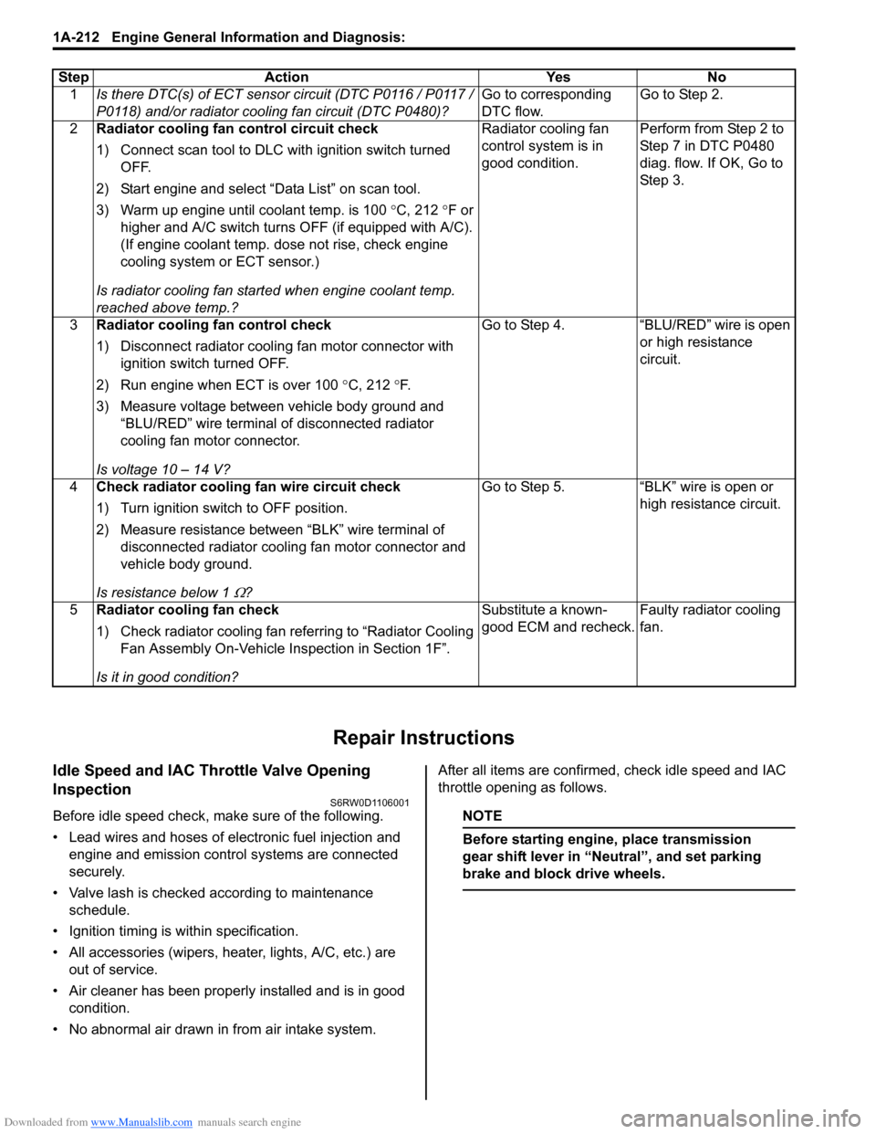
Step Action Yes No
1Is there DTC(s) of ECT sensor circuit (DTC P0116 / P0117 /
P0118) and/or radiator cooling fan circuit (DTC P0480)?Go to corresponding
DTC flow.Go to Step 2.
2Radiator cooling fan control circuit check
1) Connect scan tool to DLC with ignition switch turned
OFF.
2) Start engine and select “Data List” on scan tool.
3) Warm up engine until coolant temp. is 100 °C, 212 °F or
higher and A/C switch turns OFF (if equipped with A/C).
(If engine coolant temp. dose not rise, check engine
cooling system or ECT sensor.)
Is radiator cooling fan started when engine coolant temp.
reached above temp.?Radiator cooling fan
control system is in
good condition.Perform from Step 2 to
Step 7 in DTC P0480
diag. flow. If OK, Go to
Ste p 3.
3Radiator cooling fan control check
1) Disconnect radiator cooling fan motor connector with
ignition switch turned OFF.
2) Run engine when ECT is over 100 °C, 212 °F.
3) Measure voltage between vehicle body ground and
“BLU/RED” wire terminal of disconnected radiator
cooling fan motor connector.
Is voltage 10 – 14 V?Go to Step 4. “BLU/RED” wire is open
or high resistance
circuit.
4Check radiator cooling fan wire circuit check
1) Turn ignition switch to OFF position.
2) Measure resistance between “BLK” wire terminal of
disconnected radiator cooling fan motor connector and
vehicle body ground.
Is resistance below 1
Ω?Go to Step 5. “BLK” wire is open or
high resistance circuit.
5Radiator cooling fan check
1) Check radiator cooling fan referring to “Radiator Cooling
Fan Assembly On-Vehicle Inspection in Section 1F”.
Is it in good condition?Substitute a known-
good ECM and recheck.Faulty radiator cooling
fan.
Page 278 of 1556
Downloaded from www.Manualslib.com manuals search engine 1C-10 Engine Electrical Devices:
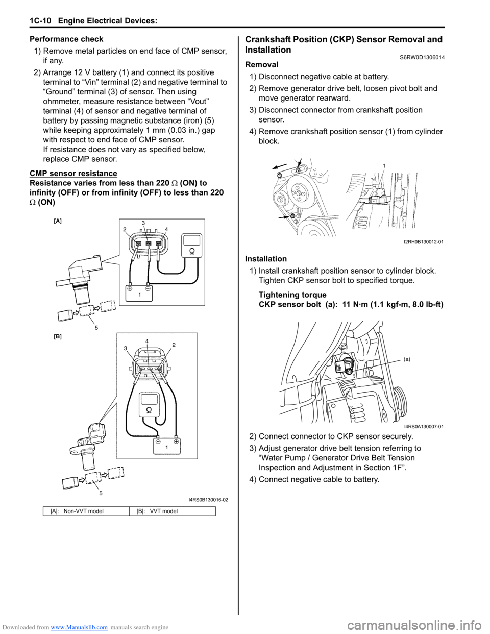
Performance check
1) Remove metal particles on end face of CMP sensor,
if any.
2) Arrange 12 V battery (1) and connect its positive
terminal to “Vin” terminal (2) and negative terminal to
“Ground” terminal (3) of sensor. Then using
ohmmeter, measure resistance between “Vout”
terminal (4) of sensor and negative terminal of
battery by passing magnetic substance (iron) (5)
while keeping approximately 1 mm (0.03 in.) gap
with respect to end face of CMP sensor.
If resistance does not vary as specified below,
replace CMP sensor.
CMP sensor resistance
Resistance varies from less than 220 Ω (ON) to
infinity (OFF) or from infinity (OFF) to less than 220
Ω (ON)
Crankshaft Position (CKP) Sensor Removal and
Installation
S6RW0D1306014
Removal
1) Disconnect negative cable at battery.
2) Remove generator drive belt, loosen pivot bolt and
move generator rearward.
3) Disconnect connector from crankshaft position
sensor.
4) Remove crankshaft position sensor (1) from cylinder
block.
Installation
1) Install crankshaft position sensor to cylinder block.
Tighten CKP sensor bolt to specified torque.
Tightening torque
CKP sensor bolt (a): 11 N·m (1.1 kgf-m, 8.0 lb-ft)
2) Connect connector to CKP sensor securely.
3) Adjust generator drive belt tension referring to
“Water Pump / Generator Drive Belt Tension
Inspection and Adjustment in Section 1F”.
4) Connect negative cable to battery.
[A]: Non-VVT model [B]: VVT model
I4RS0B130016-02
I2RH0B130012-01
(a)
I4RS0A130007-01
Page 279 of 1556
Downloaded from www.Manualslib.com manuals search engine Engine Electrical Devices: 1C-11
Crankshaft Position (CKP) Sensor InspectionS6RW0D1306015
Visual check
• Check that O-ring is free from damage.
• Check that end face of sensor and signal pulley tooth
are free from any metal particles and damage.
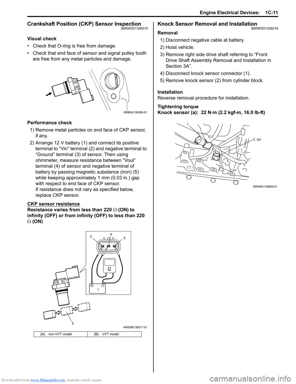
Performance check
1) Remove metal particles on end face of CKP sensor,
if any.
2) Arrange 12 V battery (1) and connect its positive
terminal to “Vin” terminal (2) and negative terminal to
“Ground” terminal (3) of sensor. Then using
ohmmeter, measure resistance between “Vout”
terminal (4) of sensor and negative terminal of
battery by passing magnetic substance (iron) (5)
while keeping approximately 1 mm (0.03 in.) gap
with respect to end face of CKP sensor.
If resistance does not vary as specified below,
replace CKP sensor.
CKP sensor resistance
Resistance varies from less than 220 Ω (ON) to
infinity (OFF) or from infinity (OFF) to less than 220
Ω (ON)
Knock Sensor Removal and InstallationS6RW0D1306016
Removal
1) Disconnect negative cable at battery.
2) Hoist vehicle.
3) Remove right side drive shaft referring to “Front
Drive Shaft Assembly Removal and Installation in
Section 3A”.
4) Disconnect knock sensor connector (1).
5) Remove knock sensor (2) from cylinder block.
Installation
Reverse removal procedure for installation.
Tightening torque
Knock sensor (a): 22 N·m (2.2 kgf-m, 16.0 lb-ft)
[A]: non-VVT model [B]: VVT model
I3RB0A130006-01
I4RS0B130017-01
1
2, (a)
I5RW0A130009-01
Page 285 of 1556
Downloaded from www.Manualslib.com manuals search engine Engine Mechanical: 1D-3
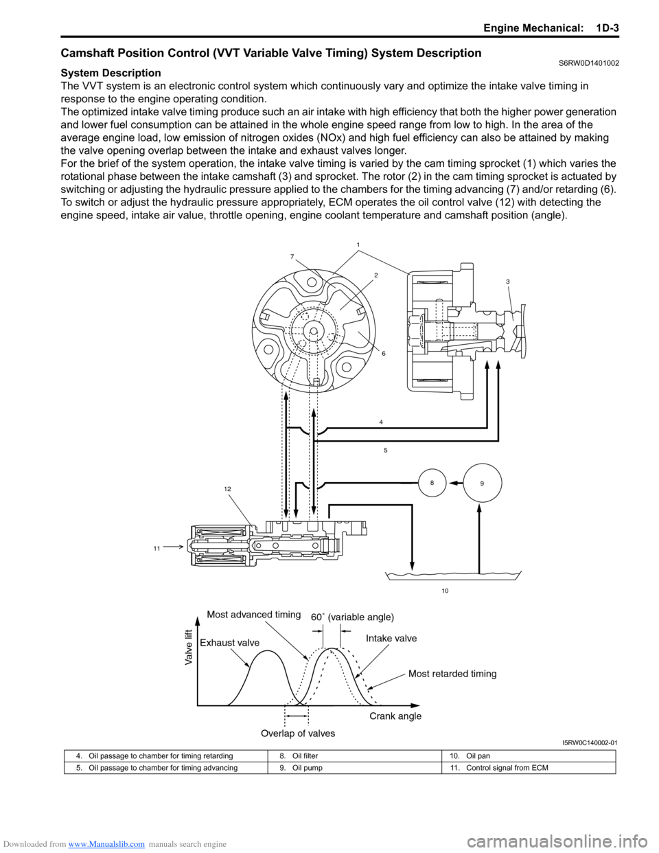
Camshaft Position Control (VVT Variable Valve Timing) System DescriptionS6RW0D1401002
System Description
The VVT system is an electronic control system which continuously vary and optimize the intake valve timing in
response to the engine operating condition.
The optimized intake valve timing produce such an air intake with high efficiency that both the higher power generation
and lower fuel consumption can be attained in the whole engine speed range from low to high. In the area of the
average engine load, low emission of nitrogen oxides (NOx) and high fuel efficiency can also be attained by making
the valve opening overlap between the intake and exhaust valves longer.
For the brief of the system operation, the intake valve timing is varied by the cam timing sprocket (1) which varies the
rotational phase between the intake camshaft (3) and sprocket. The rotor (2) in the cam timing sprocket is actuated by
switching or adjusting the hydraulic pressure applied to the chambers for the timing advancing (7) and/or retarding (6).
To switch or adjust the hydraulic pressure appropriately, ECM operates the oil control valve (12) with detecting the
engine speed, intake air value, throttle opening, engine coolant temperature and camshaft position (angle).
1
4
5
10
8
9
2
7
6
12
11
3
60˚ (variable angle)
Most retarded timing Most advanced timing
Exhaust valveIntake valve
Crank angle
Overlap of valves
Valve lift
I5RW0C140002-01
4. Oil passage to chamber for timing retarding 8. Oil filter 10. Oil pan
5. Oil passage to chamber for timing advancing 9. Oil pump 11. Control signal from ECM
Page 290 of 1556
Downloaded from www.Manualslib.com manuals search engine 1D-8 Engine Mechanical:
2) Lift down the valve by turning crankshaft to 360°.
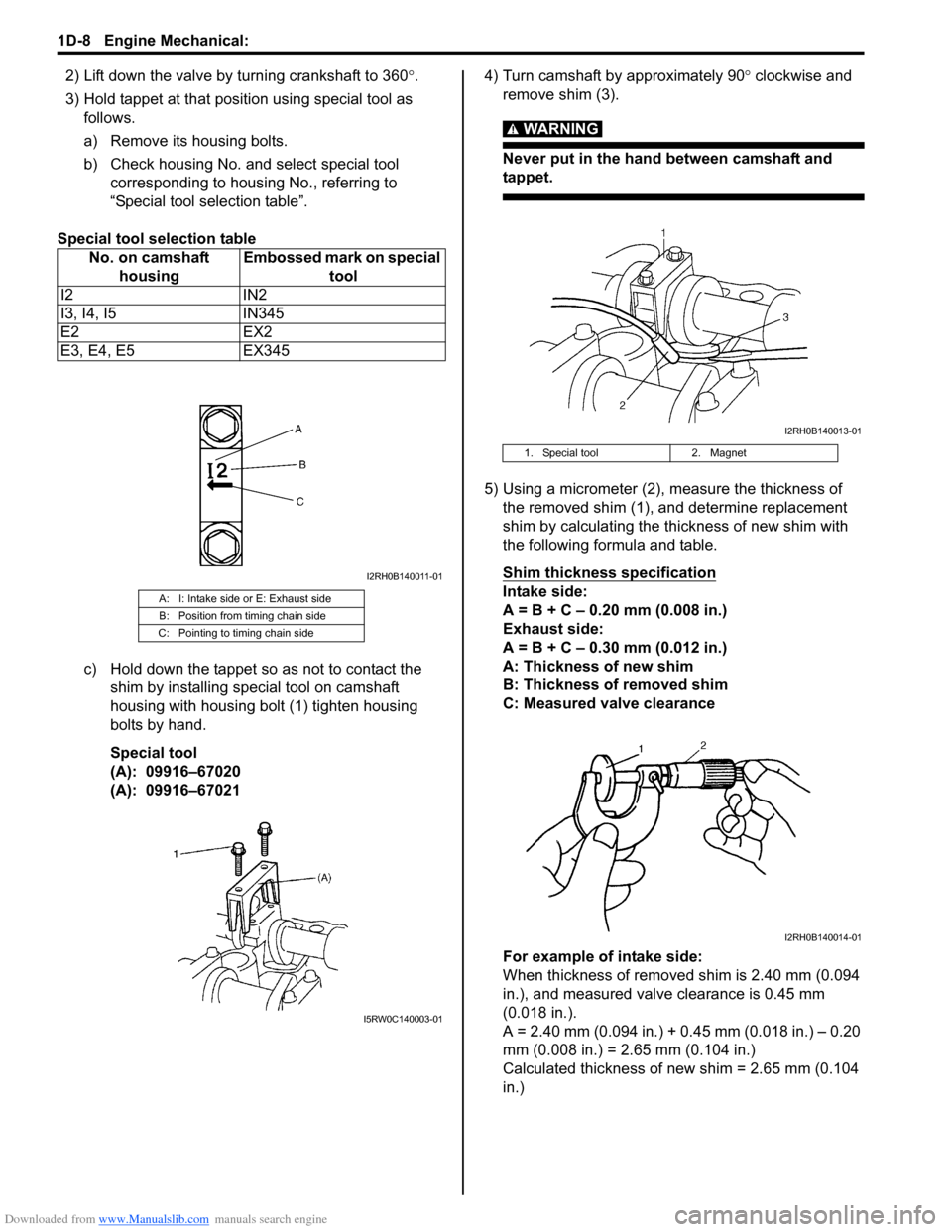
3) Hold tappet at that position using special tool as
follows.
a) Remove its housing bolts.
b) Check housing No. and select special tool
corresponding to housing No., referring to
“Special tool selection table”.
Special tool selection table
c) Hold down the tappet so as not to contact the
shim by installing special tool on camshaft
housing with housing bolt (1) tighten housing
bolts by hand.
Special tool
(A): 09916–67020
(A): 09916–670214) Turn camshaft by approximately 90° clockwise and
remove shim (3).
WARNING!
Never put in the hand between camshaft and
tappet.
5) Using a micrometer (2), measure the thickness of
the removed shim (1), and determine replacement
shim by calculating the thickness of new shim with
the following formula and table.
Shim thickness specification
Intake side:
A = B + C – 0.20 mm (0.008 in.)
Exhaust side:
A = B + C – 0.30 mm (0.012 in.)
A: Thickness of new shim
B: Thickness of removed shim
C: Measured valve clearance
For example of intake side:
When thickness of removed shim is 2.40 mm (0.094
in.), and measured valve clearance is 0.45 mm
(0.018 in.).
A = 2.40 mm (0.094 in.) + 0.45 mm (0.018 in.) – 0.20
mm (0.008 in.) = 2.65 mm (0.104 in.)
Calculated thickness of new shim = 2.65 mm (0.104
in.) No. on camshaft
housingEmbossed mark on special
tool
I2 IN2
I3, I4, I5 IN345
E2 EX2
E3, E4, E5 EX345A: I: Intake side or E: Exhaust side
B: Position from timing chain side
C: Pointing to timing chain side
I2RH0B140011-01
I5RW0C140003-01
1. Special tool 2. Magnet
I2RH0B140013-01
I2RH0B140014-01
Page 309 of 1556
Downloaded from www.Manualslib.com manuals search engine Engine Mechanical: 1D-27
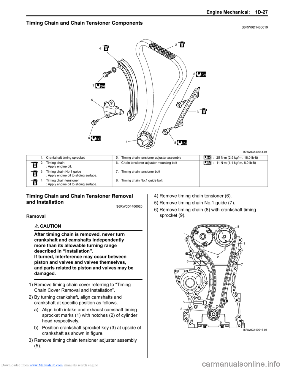
Timing Chain and Chain Tensioner ComponentsS6RW0D1406019
Timing Chain and Chain Tensioner Removal
and Installation
S6RW0D1406020
Removal
CAUTION!
After timing chain is removed, never turn
crankshaft and camshafts independently
more than its allowable turning range
described in “Installation”.
If turned, interference may occur between
piston and valves and valves themselves,
and parts related to piston and valves may be
damaged.
1) Remove timing chain cover referring to “Timing
Chain Cover Removal and Installation”.
2) By turning crankshaft, align camshafts and
crankshaft at specific position as follows.
a) Align both intake and exhaust camshaft timing
sprocket marks (1) with notches (2) of cylinder
head respectively.
b) Position crankshaft sprocket key (3) at upside of
crankshaft as shown in figure.
3) Remove timing chain tensioner adjuster assembly
(5).4) Remove timing chain tensioner (6).
5) Remove timing chain No.1 guide (7).
6) Remove timing chain (8) with crankshaft timing
sprocket (9).
I5RW0C140044-01
1. Crankshaft timing sprocket 5. Timing chain tensioner adjuster assembly : 25 N⋅m (2.5 kgf-m, 18.0 lb-ft)
2. Timing chain
: Apply engine oil.6. Chain tensioner adjuster mounting bolt : 11 N⋅m (1.1 kgf-m, 8.0 lb-ft)
3. Timing chain No.1 guide
: Apply engine oil to sliding surface.7. Timing chain tensioner bolt
4. Timing chain tensioner
: Apply engine oil to sliding surface.8. Timing chain No.1 guide bolt
3
1
1
2
5
67
8
9
I5RW0C140016-01
Page 333 of 1556
Downloaded from www.Manualslib.com manuals search engine Engine Mechanical: 1D-51
Pistons, Piston Rings, Connecting Rods and
Cylinders Disassembly and Assembly
S6RW0D1406033
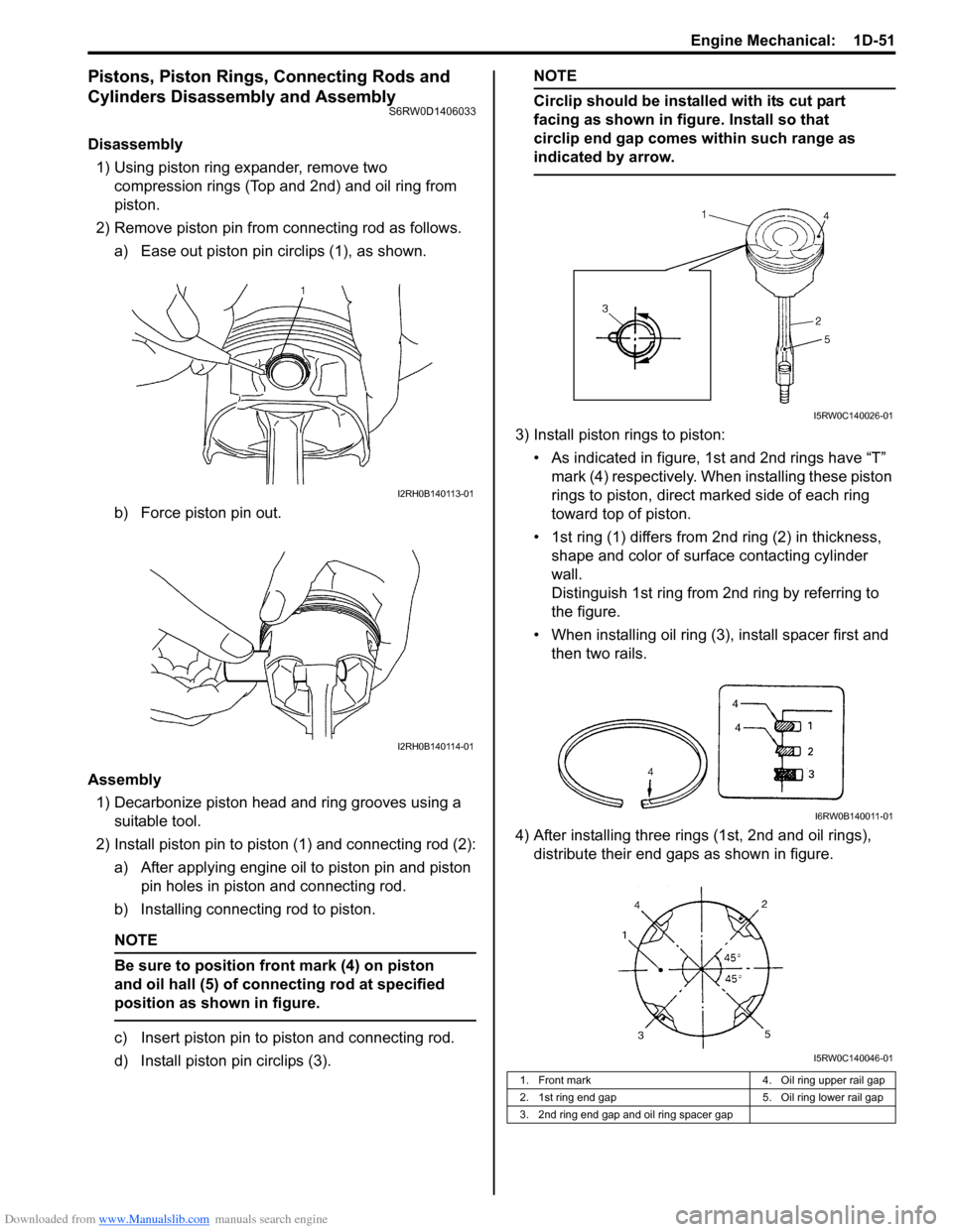
Disassembly
1) Using piston ring expander, remove two
compression rings (Top and 2nd) and oil ring from
piston.
2) Remove piston pin from connecting rod as follows.
a) Ease out piston pin circlips (1), as shown.
b) Force piston pin out.
Assembly
1) Decarbonize piston head and ring grooves using a
suitable tool.
2) Install piston pin to piston (1) and connecting rod (2):
a) After applying engine oil to piston pin and piston
pin holes in piston and connecting rod.
b) Installing connecting rod to piston.
NOTE
Be sure to position front mark (4) on piston
and oil hall (5) of connecting rod at specified
position as shown in figure.
c) Insert piston pin to piston and connecting rod.
d) Install piston pin circlips (3).
NOTE
Circlip should be installed with its cut part
facing as shown in figure. Install so that
circlip end gap comes within such range as
indicated by arrow.
3) Install piston rings to piston:
• As indicated in figure, 1st and 2nd rings have “T”
mark (4) respectively. When installing these piston
rings to piston, direct marked side of each ring
toward top of piston.
• 1st ring (1) differs from 2nd ring (2) in thickness,
shape and color of surface contacting cylinder
wall.
Distinguish 1st ring from 2nd ring by referring to
the figure.
• When installing oil ring (3), install spacer first and
then two rails.
4) After installing three rings (1st, 2nd and oil rings),
distribute their end gaps as shown in figure.
I2RH0B140113-01
I2RH0B140114-01
1. Front mark 4. Oil ring upper rail gap
2. 1st ring end gap 5. Oil ring lower rail gap
3. 2nd ring end gap and oil ring spacer gap
I5RW0C140026-01
I6RW0B140011-01
I5RW0C140046-01
Page 339 of 1556
Downloaded from www.Manualslib.com manuals search engine Engine Mechanical: 1D-57
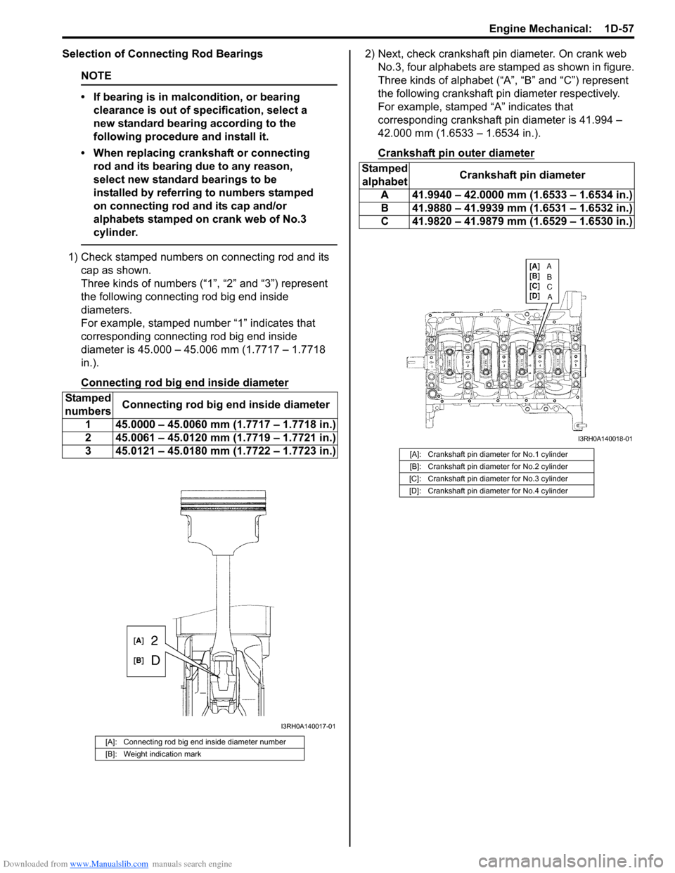
Selection of Connecting Rod Bearings
NOTE
• If bearing is in malcondition, or bearing
clearance is out of specification, select a
new standard bearing according to the
following procedure and install it.
• When replacing crankshaft or connecting
rod and its bearing due to any reason,
select new standard bearings to be
installed by referring to numbers stamped
on connecting rod and its cap and/or
alphabets stamped on crank web of No.3
cylinder.
1) Check stamped numbers on connecting rod and its
cap as shown.
Three kinds of numbers (“1”, “2” and “3”) represent
the following connecting rod big end inside
diameters.
For example, stamped number “1” indicates that
corresponding connecting rod big end inside
diameter is 45.000 – 45.006 mm (1.7717 – 1.7718
in.).
Connecting rod big end inside diameter
2) Next, check crankshaft pin diameter. On crank web
No.3, four alphabets are stamped as shown in figure.
Three kinds of alphabet (“A”, “B” and “C”) represent
the following crankshaft pin diameter respectively.
For example, stamped “A” indicates that
corresponding crankshaft pin diameter is 41.994 –
42.000 mm (1.6533 – 1.6534 in.).
Crankshaft pin outer diameter
Stamped
numbersConnecting rod big end inside diameter
1 45.0000 – 45.0060 mm (1.7717 – 1.7718 in.)
2 45.0061 – 45.0120 mm (1.7719 – 1.7721 in.)
3 45.0121 – 45.0180 mm (1.7722 – 1.7723 in.)
[A]: Connecting rod big end inside diameter number
[B]: Weight indication mark
I3RH0A140017-01
Stamped
alphabetCrankshaft pin diameter
A 41.9940 – 42.0000 mm (1.6533 – 1.6534 in.)
B 41.9880 – 41.9939 mm (1.6531 – 1.6532 in.)
C 41.9820 – 41.9879 mm (1.6529 – 1.6530 in.)
[A]: Crankshaft pin diameter for No.1 cylinder
[B]: Crankshaft pin diameter for No.2 cylinder
[C]: Crankshaft pin diameter for No.3 cylinder
[D]: Crankshaft pin diameter for No.4 cylinder
I3RH0A140018-01
Page 348 of 1556
Downloaded from www.Manualslib.com manuals search engine 1D-66 Engine Mechanical:
Selection of Main Bearings
Standard bearing
If bearing is in malcondition, or bearing clearance is out
of specification, select a new standard bearing according
to the following procedure and install it.
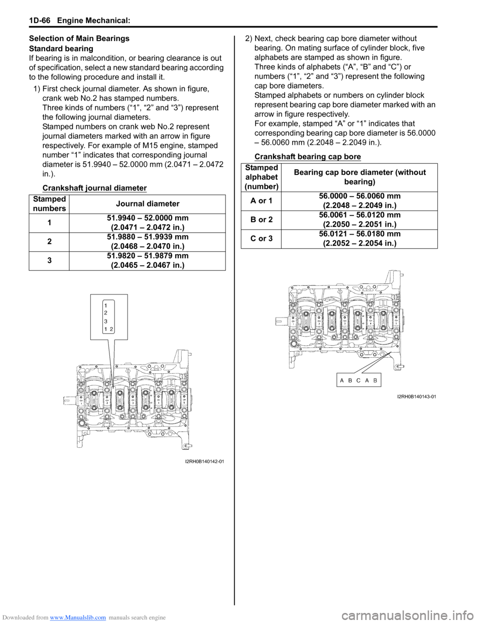
1) First check journal diameter. As shown in figure,
crank web No.2 has stamped numbers.
Three kinds of numbers (“1”, “2” and “3”) represent
the following journal diameters.
Stamped numbers on crank web No.2 represent
journal diameters marked with an arrow in figure
respectively. For example of M15 engine, stamped
number “1” indicates that corresponding journal
diameter is 51.9940 – 52.0000 mm (2.0471 – 2.0472
in.).
Crankshaft journal diameter2) Next, check bearing cap bore diameter without
bearing. On mating surface of cylinder block, five
alphabets are stamped as shown in figure.
Three kinds of alphabets (“A”, “B” and “C”) or
numbers (“1”, “2” and “3”) represent the following
cap bore diameters.
Stamped alphabets or numbers on cylinder block
represent bearing cap bore diameter marked with an
arrow in figure respectively.
For example, stamped “A” or “1” indicates that
corresponding bearing cap bore diameter is 56.0000
– 56.0060 mm (2.2048 – 2.2049 in.).
Crankshaft bearing cap bore
Stamped
numbersJournal diameter
151.9940 – 52.0000 mm
(2.0471 – 2.0472 in.)
251.9880 – 51.9939 mm
(2.0468 – 2.0470 in.)
351.9820 – 51.9879 mm
(2.0465 – 2.0467 in.)
I2RH0B140142-01
Stamped
alphabet
(number)Bearing cap bore diameter (without
bearing)
A or 156.0000 – 56.0060 mm
(2.2048 – 2.2049 in.)
B or 256.0061 – 56.0120 mm
(2.2050 – 2.2051 in.)
C or 356.0121 – 56.0180 mm
(2.2052 – 2.2054 in.)
I2RH0B140143-01
Page 378 of 1556
Downloaded from www.Manualslib.com manuals search engine 1G-1 Fuel System:
Engine
Fuel System
Precautions
Precautions on Fuel System ServiceS6RW0D1700001
WARNING!
Before attempting service of any type on fuel system, the following should be always observed in
order to reduce the risk of fire and personal injury.
• Disconnect negative cable at battery.
• Do not smoke, and place no smoking signs near work area.
• Be sure to have CO
2 fire extinguisher handy.
• Be sure to perform work in a well-ventilated area and away from any open flames (such as gas hot
heater).
• Wear safety glasses.
• To relieve fuel vapor pressure in fuel tank, remove fuel filler cap from fuel filler neck and then
reinstall it.
• As fuel feed line is still under high fuel pressure even after stopping engine, loosening or
disconnecting fuel feed line directly may cause dangerous spout of fuel. Before loosening or
disconnecting fuel feed line, make sure to relieve fuel pressure referring to “Fuel Pressure Relief
Procedure”.
• A small amount of fuel may be released when the fuel line is disconnected. In order to reduce the
risk of personal injury, cover a shop cloth to the fitting to be disconnected. Be sure to put that cloth
in an approved container after disconnecting.
• Never run engine with fuel pump relay disconnected when engine and exhaust system are hot.
• Note that fuel hose connection varies with each type of pipe. Be sure to connect and clamp each
hose correctly referring to “Fuel Hose Disconnecting and Reconnecting”.
After connecting, make sure that it has no twist or kink.
• When installing injector or fuel feed pipe, lubricate its O-ring with gasoline.
• When servicing the fuel tank, it should be treated with respect, with no contact with sharp edges or
hot surfaces. In addition, the fuel tank should not be dropped since fuel tank, fuel pump and other
components can be damaged by the impact. If dropped, all components should be replaced because
there is a risk of damage.
• The fuel tank is made of resin.
Be sure not to allow solvent (chemical article such as grease and sealant) to attach to the fuel tank
as some chemical reaction may occur, causing the fuel tank to be swollen, hardened or distorted
leakage and resulting in fuel leakage from the fuel tank.