check engine SUZUKI SX4 2006 1.G Service Workshop Manual
[x] Cancel search | Manufacturer: SUZUKI, Model Year: 2006, Model line: SX4, Model: SUZUKI SX4 2006 1.GPages: 1556, PDF Size: 37.31 MB
Page 1015 of 1556

Downloaded from www.Manualslib.com manuals search engine Air Conditioning System: Automatic Type 7B-75
DTC B1570: Engine Type Signal FailureS6RW0D7224027
DTC Detecting Condition and Trouble Area
DTC Troubleshooting
DTC B1571: Combination Meter Spec Signal FailureS6RW0D7224028
DTC Detecting Condition and Trouble Area
DTC TroubleshootingDTC detecting condition Trouble area
HVAC control module receives invalid data of engine type signal from BCM. • CAN communication circuit
• HVAC control module
•ECM
Step Action Yes No
1Was “Air Conditioning System Check” performed?Go to Step 2. Go to “Air Conditioning
System Check”.
2Scan tool data check
1) Connect scan tool with ignition switch turned OFF
position.
2) Ignition switch turned ON and select “DATA LIST” mode.
3) Check “ENGINE TYPE” displayed on scan tool.
Is value of engine type signal within specified ranges
indicated in “Scan Tool Data”?Substitute a known
good HVAC control
module and recheck.Go to step 3.
3Scan tool data check
1) Check “ENGINE TYPE” displayed on scan tool.
Is “CAN Err” displayed on scan tool data?Check CAN
communication circuit
referring to “DTC Check
in Section 1A”.Substitute a known
good ECM and recheck.
DTC detecting condition Trouble area
HVAC control module receives invalid data of Combination meter spec signal
from BCM.• CAN communication circuit
• Combination meter
• HVAC control module
Step Action Yes No
1Was “Air Conditioning System Check” performed?Go to Step 2. Go to “Air Conditioning
System Check”.
2Scan tool data check
1) Connect scan tool with ignition switch turned OFF
position.
2) Ignition switch turned ON and select “DATA LIST” mode.
3) Check “METER SPEC” displayed on scan tool.
Is value of combination meter spec signal within specified
ranges indicated in “Scan Tool Data”?Substitute a known
good HVAC control
module and recheck.Go to step 3.
3Scan tool data check
1) Check “METER SPEC” displayed on scan tool.
Is “CAN Err” displayed on scan tool data?Check CAN
communication circuit
referring to “DTC Check
in Section 1A”.Substitute a known
good combination meter
and recheck.
Page 1016 of 1556

Downloaded from www.Manualslib.com manuals search engine 7B-76 Air Conditioning System: Automatic Type
Inspection of HVAC Control Module and Its CircuitS6RW0D7224029
HVAC control module and its circuits can be checked at HVAC control module wiring couplers by measuring voltage.
CAUTION!
HVAC control module can not be checked by itself. It is strictly prohibited to connect voltmeter to
HVAC control module with couplers disconnected from it.
Voltage Check
1) Remove HVAC control module referring to “HVAC Control Module Removal and Installation”.
2) Check voltage at each terminal.
NOTE
As each terminal voltage is affected by the battery voltage, confirm that it is 11 V or more when ignition
switch is ON.
G20
1 2 3 4 5 6 7 8 9 10 11 12 13 14
15 16 17 18 19 20 21 24 23 22 25 26 27 28 29 30
12
I7RW01722013-01
1. HVAC control module 2. HVAC control module connector (viewed from harness side)
Terminal Wire Color CircuitNormal
Vo l ta g eCondition
G20-1 GRY/BLUTemperature control
actuator (COOL)10 – 14 VIgnition switch turned ON, temperature control
actuator is working in operation from HOT to COOL
position
0 – 2 VIgnition switch turned ON, except the above
condition
G20-2 GRY/REDTemperature control
actuator (HOT)10 – 14 VIgnition switch turned ON, temperature control
actuator is working in operation from COOL to HOT
position
0 – 2 VIgnition switch turned ON, except the above
condition
G20-3 BLUSerial communication line
of data link connector10 – 14 V Ignition switch turned ON
G20-4 GRN/YEL Rear defogger switchRefer to “Reference waveform No. 1: Automatic Type”.
G20-5 BLK/YEL Illumination ground 0 – 1 V Full-time
G20-6 RED/YEL Illumination switch0 – 1 VIgnition switch turned ON, lighting switch OFF
position
10 – 14 V Ignition switch turned ON, lighting switch ON position
G20-7 WHT/REDElectric power source for
back-up10 – 14 V Constantly
Page 1019 of 1556

Downloaded from www.Manualslib.com manuals search engine Air Conditioning System: Automatic Type 7B-79
Reference waveform No. 1
Rear defogger switch or A/C switch signal (1)Reference waveform No. 2
Serial communication line of BCM (1)
A/C System Inspection at ECMS6RW0D7224030
When checking voltage at ECM terminals related to A/C system, refer to “Inspection of ECM and Its Circuits in Section
1A”.
Repair Instructions
Operation Procedure for Refrigerant ChargeS6RW0D7226001
Refer to “Operation Procedure for Refrigerant Charge”.Measurement terminal Rear defogger switch
CH1: “G20-4” to “G20-23” A/
C switch
CH1: “G20-21” to “G20-23”
Oscilloscope setting CH1: 5 V / DIV
TIME: 10 ms / DIV
Measurement condition Rear defogger switch:
• Ignition switch is at ON
position and rear defogger
switch is not pushed
A/C switch:
• Ignition switch is at ON
position and A/C switch is
not pushed
I7RW01722014-02
Measurement terminal CH1: “G20-13” to “G20-23”
Oscilloscope setting CH1: 5 V / DIV
TIME: 20 ms / DIV
Measurement condition Ignition switch is at ON
position
I7RW01722015-02
Page 1022 of 1556

Downloaded from www.Manualslib.com manuals search engine 7B-82 Air Conditioning System: Automatic Type
6) Measure output voltage variation while temperature
control actuator is operated from “MAX COOL”
position (B) to “MAX HOT” position (A) as following
specification.
If measure voltage is out of specification or does not
vary linearly as the shown in graph, check related
wire circuit and HVAC control module. If wire circuits
and HVAC control module are OK, go to next step.
Temperature control actuator output voltage
0.48 – 4.53V (linear variation as following graph)
7) Set temperature selector of HVAC control module to
“MAX HOT” position with ignition switch turned ON,
and make sure if the position of actuator lever is
“MAX HOT” position (A).
8) Turn ignition switch to OFF position, and then
disconnect connector from temperature control
actuator.9) Measure resistance between terminal “1” and “2”.
Temperature control actuator resistance between
terminal “1” and “2” (MAX HOT position)
(Reference value)
Approx. 0.45 kΩ at 25 °C (77 °F)
10) Connect connector to temperature control actuator.
11) Set temperature selector of HVAC control module to
“MAX COOL” position with ignition switch turned ON,
and make sure if the position of actuator lever is
“MAX COOL” position (B).
12) Turn ignition switch to OFF position, and then
disconnect connector from temperature control
actuator.
13) Measure resistance between terminal “1” and “2”.
Temperature control actuator resistance between
terminal “1” and “2” (MAX COOL position)
(Reference value)
Approx. 4.3 kΩ at 25 °C (77 °F)
If measure resistance is out of specification, replace the
actuator with new one.[A]: MAX HOT
[B]: MAX COOL
[C]: Actuator lever position
123456
6
M5
3
2
1
AB
4.53
0.48 5.00(V)
[C]
[A] [B]
I7RW01722017-03
123456
6
M5
3
2
1
A
I7RW01722020-02
123456
6
M5
3
2
1
B
I7RW01722021-02
Page 1023 of 1556

Downloaded from www.Manualslib.com manuals search engine Air Conditioning System: Automatic Type 7B-83
Air Flow Control Actuator Removal and
Installation
S6RW0D7226006
Removal
1) Disconnect negative cable at battery.
2) Remove steering column hole cover from instrument
panel.
3) Remove driver side foot duct from HVAC unit.
4) Disconnect air flow control actuator connector (2).
5) Remove air flow control actuator (1) from HVAC unit
by removing screws (3).
Installation
Reverse removal procedure noting the following
instructions.
• Before installing actuator, make sure that position of
actuator lever is in between “BENT” position and
“DEF” position.
• Be sure to insert pin (1) of air flow control actuator into
the groove (2) of link.
Air Flow Control Actuator and Its Circuit
Inspection
S6RW0D7226007
1) Remove air flow control actuator from HVAC unit
referring to “Air Flow Control Actuator Removal and
Installation”.
2) Connect connector to air flow control actuator.
3) Set air flow selector to “BENT” position with ignition
switch turned ON.
4) Connect voltage meter between terminal “2” and
body ground.
5) Turn air flow selector to “DEF” position.
6) Measure output voltage variation while air flow
control actuator is operated from “BENT” position (A)
to “DEF” position (B) as following specification.
If measure voltage is out of specification or does not
vary linearly as the shown in graph, check related
wire circuit and HVAC control module. If wire circuits
and HVAC control module are OK, go to next step.
Air flow control actuator output voltage
0.48 – 4.53 V (linear variation as following graph)
13
2
I7RW01722022-01
1
2
I7RW01722023-02
[A]: BENT [D]: FOOT
[B]: DEF [E]: DEF / FOOT
[C]: BI-LEVEL [F]: Actuator lever position
123456
6
M5
3
2
1 A
B
(V)
4.53
3.35
2.60
1.78
0.48
[A][B]
[C] [D] [E][F]5.00
I7RW01722024-02
Page 1024 of 1556

Downloaded from www.Manualslib.com manuals search engine 7B-84 Air Conditioning System: Automatic Type
7) Set air flow selector of HVAC control module to
“DEF” position with ignition switch turned ON, and
make sure if the position of actuator lever is “DEF”
position (A).
8) Turn ignition switch to OFF position, and then
disconnect connector from air flow control actuator.
9) Measure resistance between terminal “1” and “2”.
Air flow control actuator resistance between
terminal “1” and “2” (DEF position) (Reference
value)
Approx. 0.45 kΩ at 25 °C (77 °F)
10) Connect connector to air flow control actuator.
11) Set air flow selector of HVAC control module to
“VENT” position with ignition switch turned ON, and
make sure if the position of actuator lever is “VENT”
position (B).
12) Turn ignition switch to OFF position, and then
disconnect connector from air flow control actuator.13) Measure resistance between terminal “1” and “2”.
Air flow control actuator resistance between
terminal “1” and “2” (VENT position) (Reference
value)
Approx. 4.3 kΩ at 25 °C (77 °F)
If measure resistance is out of specification, replace the
actuator with new one.
Air Intake Actuator Removal and InstallationS6RW0D7226008
Remove and install air intake actuator referring to “Air
Intake Control Actuator Removal and Installation in
Section 7A”.
Air Intake Actuator InspectionS6RW0D7226009
For inspection, refer to “Air Intake Control Actuator
Inspection in Section 7A”.
Actuator Linkage InspectionS6RW0D7226010
• Check if each actuator linkage operates smoothly.
• Check actuator rod for bend.
• Check each actuator linkage for breakage.
• Make sure if there is not any obstruction in operating
range of actuator linkage.
If any malfunction is found, repair or replace faulty
part(s).
Blower Motor Controller Removal and
Installation
S6RW0D7226011
Refer to “Blower Motor Resistor Removal and
Installation in Section 7A”.
123456
6
M5
3
2
1 A
I7RW01722025-01
123456
6
M5
3
2
1 B
I7RW01722026-01
Page 1025 of 1556

Downloaded from www.Manualslib.com manuals search engine Air Conditioning System: Automatic Type 7B-85
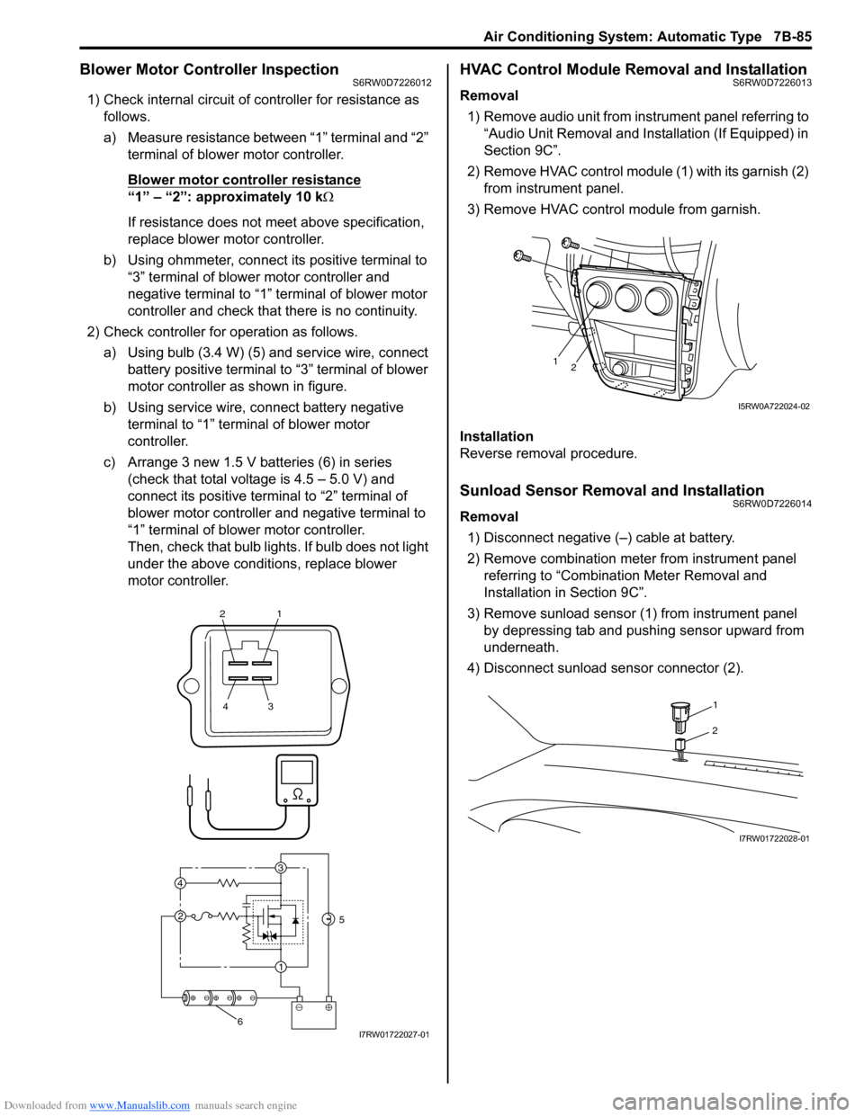
Blower Motor Controller InspectionS6RW0D7226012
1) Check internal circuit of controller for resistance as
follows.
a) Measure resistance between “1” terminal and “2”
terminal of blower motor controller.
Blower motor controller resistance
“1” – “2”: approximately 10 kΩ
If resistance does not meet above specification,
replace blower motor controller.
b) Using ohmmeter, connect its positive terminal to
“3” terminal of blower motor controller and
negative terminal to “1” terminal of blower motor
controller and check that there is no continuity.
2) Check controller for operation as follows.
a) Using bulb (3.4 W) (5) and service wire, connect
battery positive terminal to “3” terminal of blower
motor controller as shown in figure.
b) Using service wire, connect battery negative
terminal to “1” terminal of blower motor
controller.
c) Arrange 3 new 1.5 V batteries (6) in series
(check that total voltage is 4.5 – 5.0 V) and
connect its positive terminal to “2” terminal of
blower motor controller and negative terminal to
“1” terminal of blower motor controller.
Then, check that bulb lights. If bulb does not light
under the above conditions, replace blower
motor controller.
HVAC Control Module Removal and InstallationS6RW0D7226013
Removal
1) Remove audio unit from instrument panel referring to
“Audio Unit Removal and Installation (If Equipped) in
Section 9C”.
2) Remove HVAC control module (1) with its garnish (2)
from instrument panel.
3) Remove HVAC control module from garnish.
Installation
Reverse removal procedure.
Sunload Sensor Removal and InstallationS6RW0D7226014
Removal
1) Disconnect negative (–) cable at battery.
2) Remove combination meter from instrument panel
referring to “Combination Meter Removal and
Installation in Section 9C”.
3) Remove sunload sensor (1) from instrument panel
by depressing tab and pushing sensor upward from
underneath.
4) Disconnect sunload sensor connector (2).
21
43
3
1 2 4
5
6I7RW01722027-01
12
I5RW0A722024-02
1
2
I7RW01722028-01
Page 1026 of 1556

Downloaded from www.Manualslib.com manuals search engine 7B-86 Air Conditioning System: Automatic Type
Installation
Reverse removal procedure noting the following
instructions.
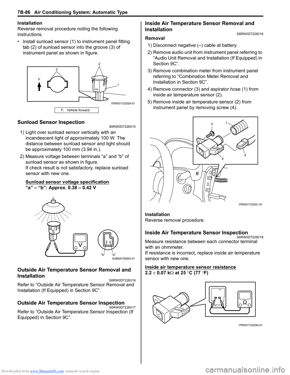
• Install sunload sensor (1) to instrument panel fitting
tab (2) of sunload sensor into the groove (3) of
instrument panel as shown in figure.
Sunload Sensor InspectionS6RW0D7226015
1) Light over sunload sensor vertically with an
incandescent light of approximately 100 W. The
distance between sunload sensor and light should
be approximately 100 mm (3.94 in.).
2) Measure voltage between terminals “a” and “b” of
sunload sensor as shown in figure.
If check result is not satisfactory, replace sunload
sensor with new one.
Sunload sensor voltage specification
“a” – “b”: Approx. 0.38 – 0.42 V
Outside Air Temperature Sensor Removal and
Installation
S6RW0D7226016
Refer to “Outside Air Temperature Sensor Removal and
Installation (If Equipped) in Section 9C”.
Outside Air Temperature Sensor InspectionS6RW0D7226017
Refer to “Outside Air Temperature Sensor Inspection (If
Equipped) in Section 9C”.
Inside Air Temperature Sensor Removal and
Installation
S6RW0D7226018
Removal
1) Disconnect negative (–) cable at battery.
2) Remove audio unit from instrument panel referring to
“Audio Unit Removal and Installation (If Equipped) in
Section 9C”.
3) Remove combination meter from instrument panel
referring to “Combination Meter Removal and
Installation in Section 9C”.
4) Remove connector (3) and aspirator hose (1) from
inside air temperature sensor (2).
5) Remove inside air temperature sensor (2) from
instrument panel by removing screw (4).
Installation
Reverse removal procedure.
Inside Air Temperature Sensor InspectionS6RW0D7226019
Measure resistance between each connector terminal
with an ohmmeter.
If resistance is incorrect, replace inside air temperature
sensor with new one.
Inside air temperature sensor resistance
2.2 ± 0.07 kΩ at 25 °C (77 °F)
F: Vehicle forward
2
F
1
3
I7RW01722029-01
“b” “a”I5JB0A720053-01
1
23 4
I7RW01722031-01
I7RW01722030-01
Page 1029 of 1556

Downloaded from www.Manualslib.com manuals search engine Table of Contents 8- i
8
Section 8
CONTENTS
Restraint
Precautions ................................................. 8-1
Precautions............................................................. 8-1
Precautions on Restraint ....................................... 8-1
Seat Belts ................................................. 8A-1
Precautions........................................................... 8A-1
Precautions on Service and Diagnosis of Seat
Belt .................................................................... 8A-1
General Description ............................................. 8A-2
Seat Belt Construction ........................................ 8A-2
Diagnostic Information and Procedures ............ 8A-3
Repair and Inspection Required after
Accident ............................................................ 8A-3
Repair Instructions .............................................. 8A-4
Front Seat Belt Components ............................... 8A-4
Front Seat Belt Removal and Installation ............ 8A-5
Front Seat Belt Inspection................................... 8A-6
Rear Seat Belt Components ............................... 8A-7
Rear Seat Belt Removal and Installation ............ 8A-8
Rear Seat Belt Inspection ................................... 8A-8
Specifications....................................................... 8A-8
Tightening Torque Specifications ........................ 8A-8
Air Bag System ........................................ 8B-1
Precautions........................................................... 8B-1
Precautions on Service and Diagnosis of Air
Bag System....................................................... 8B-1
Precautions on Handling and Storage of Air
Bag System Components ................................. 8B-1
Precautions on Disposal of Air Bag and Seat
Belt Pretensioner .............................................. 8B-5
General Description ............................................. 8B-5
Air Bag System Construction .............................. 8B-5
Air Bag System Block Diagram ........................... 8B-6
Air Bag System Input / Output Table .................. 8B-7
Schematic and Routing Diagram ........................ 8B-8
Air Bag System Wiring Circuit Diagram .............. 8B-8
Component Location ......................................... 8B-11
Air Bag System Components, Wiring and
Connectors Location ....................................... 8B-11
Diagnostic Information and Procedures .......... 8B-12
Air Bag Diagnostic System Check .................... 8B-12
Air Bag Diagnostic System Check Flow ............ 8B-13
DTC Table ......................................................... 8B-14DTC Check........................................................ 8B-18
DTC Clearance ................................................. 8B-18
Scan Tool Data ................................................. 8B-18
“AIR BAG” Warning Light Comes ON Steady ... 8B-19
“AIR BAG” Warning Light Does Not Come ON .. 8B-22
Serial Data Link Circuit Check .......................... 8B-23
DTC B1013: SDM Internal Failure .................... 8B-25
DTC B1014: “AIR BAG” Warning Light Circuit .. 8B-26
DTC B1016: Power Supply Voltage too High.... 8B-26
DTC B1017: Power Supply Voltage too Low .... 8B-27
DTC B1021: Front Air Bag Deployment
Record............................................................. 8B-28
DTC B1024 / B1025: Side Air-Bag
Deployment Record ........................................ 8B-29
DTC B1026: Seat Belt Pretensioner
Activation Record ............................................ 8B-29
DTC B1027: Number of Deployment Times
Exceeded Limit................................................ 8B-30
DTC B1031: Driver Air Bag Circuit High
Resistance ...................................................... 8B-31
DTC B1032: Driver Air Bag Circuit Low
Resistance ...................................................... 8B-33
DTC B1033: Driver Air Bag Circuit Shorted to
Ground ............................................................ 8B-35
DTC B1034: Driver Air Bag Circuit Shorted to
Power Supply .................................................. 8B-37
DTC B1041: Passenger Air Bag Circuit High
Resistance ...................................................... 8B-40
DTC B1042: Passenger Air Bag Circuit Low
Resistance ...................................................... 8B-43
DTC B1043: Passenger Air Bag Circuit
Shorted to Ground........................................... 8B-45
DTC B1044: Passenger Air Bag Circuit
Shorted to Power Supply ................................ 8B-46
DTC B1051 / B1055: Seat Belt Pretensioner
Circuit High Resistance ................................... 8B-48
DTC B1052 / B1056: Seat Belt Pretensioner
Circuit Low Resistance.................................... 8B-51
DTC B1053 / B1057: Seat Belt Pretensioner
Shorted to Ground........................................... 8B-52
DTC B1054 / B1058: Seat Belt Pretensioner
Circuit Shorted to Power Supply ..................... 8B-54
DTC B1061 / B1065: Side-Air Bag Circuit
High Resistance .............................................. 8B-55
Page 1030 of 1556

Downloaded from www.Manualslib.com manuals search engine 8-ii Table of Contents
DTC B1062 / B1066: Side-Air Bag Circuit Low
Resistance ...................................................... 8B-59
DTC B1063 / B1067: Side-Air Bag Circuit
Shorted to Ground .......................................... 8B-61
DTC B1064 / B1068: Side-Air Bag Circuit
Shorted to Power Supply ................................ 8B-64
DTC B1071: Driver Forward Impact-Sensor
Communication Data Inconsistent .................. 8B-66
DTC B1072: Driver Forward Impact-Sensor
Communication Data Invalid ........................... 8B-66
DTC B1073: Driver Forward Impact-Sensor
Circuit Shorted to Ground ............................... 8B-67
DTC B1074: Driver Forward Impact-Sensor
Circuit Open .................................................... 8B-68
DTC B1081 / B1091: Side Impact-Sensor No
Response ........................................................ 8B-70
DTC B1082 / B1092: Side Impact-Sensor
Communication DATA Invalid ......................... 8B-70
DTC B1083 / B1093: Side Impact-Sensor
Circuit Shorted to Ground ............................... 8B-71
DTC B1084 / B1094: Side Impact-Sensor
Circuit Open .................................................... 8B-73
DTC B1085 / B1095: Side Impact-Sensor
Communication DATA Inconsistent ................ 8B-74
DTC B1361 / B1365: Curtain-Air Bag Circuit
High Resistance .............................................. 8B-75
DTC B1362 / B1366: Curtain-Air Bag Circuit
Low Resistance ............................................... 8B-79
DTC B1363 / B1367: Curtain-Air Bag Circuit
Shorted to Ground .......................................... 8B-81
DTC B1364 / B1368: Curtain-Air Bag Circuit
Shorted to Power Supply ................................ 8B-83
SDM Power Supply and Ground Circuit
Check .............................................................. 8B-85
Contact Coil Cable and Its Circuit Check .......... 8B-87
Inspection of Intermittent and Poor
Connections .................................................... 8B-89Repair and Inspection Required after
Accident .......................................................... 8B-90
Repair Instructions ............................................8B-93
Disabling Air Bag System.................................. 8B-93
Enabling Air Bag System .................................. 8B-93
SDM Removal and Installation .......................... 8B-94
SDM Inspection ................................................. 8B-95
Driver Air Bag (Inflator) Module Removal and
Installation ....................................................... 8B-95
Driver Air Bag (Inflator) Module Inspection ....... 8B-97
Passenger Air Bag (Inflator) Module Removal
and Installation ................................................ 8B-97
Passenger Air Bag (Inflator) Module
Inspection ........................................................ 8B-99
Side-Air Bag (Inflator) Module Removal and
Installation ....................................................... 8B-99
Side-Air Bag (Inflator) Inspection .................... 8B-101
Side Curtain-Air Bag (Inflator) Module
Removal and Installation ............................... 8B-102
Side Curtain-Air Bag (Inflator) Module
Inspection ...................................................... 8B-103
Forward Impact-Sensor Removal and
Installation ..................................................... 8B-103
Forward Impact-Sensor Inspection ................. 8B-104
Side Impact-Sensor Removal and Installation 8B-105
Side Impact-Sensor Inspection ....................... 8B-105
Passenger Air Bag (Inflator) Module Repair
Harness Installation....................................... 8B-106
Air Bag (Inflator) Module and Seat Belt
Pretensioner Disposal ................................... 8B-107
Deployed Air Bag (Inflator) Module and
Activated Seat Belt Pretensioner Disposal.... 8B-117
Specifications ...................................................8B-118
Tightening Torque Specifications .................... 8B-118
Special Tools and Equipment .........................8B-118
Use of Special Tools ....................................... 8B-118
Special Tool .................................................... 8B-120