Brake light SUZUKI SX4 2006 1.G Service Repair Manual
[x] Cancel search | Manufacturer: SUZUKI, Model Year: 2006, Model line: SX4, Model: SUZUKI SX4 2006 1.GPages: 1556, PDF Size: 37.31 MB
Page 1185 of 1556

Downloaded from www.Manualslib.com manuals search engine Wiring Systems: 9A-18
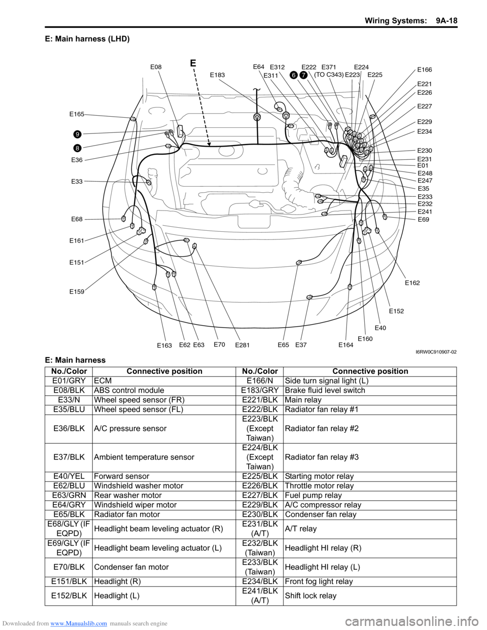
E: Main harness (LHD)
E: Main harness
E40
E33
E165
E36
E161
E68
E151
E159
E70E281E163E62E63E65E37E164
E64
E183
E08
E311
E312E222E224E225E223
E221
E371
(TO C343)E166
E227
E229
E234
E230
E01
E35
E69 E248
E247
E233
E232
E241
E162
E152
E160
E231
E226
8
9
76
E
I6RW0C910907-02
No./Color Connective position No./Color Connective position
E01/GRY ECM E166/N Side turn signal light (L)
E08/BLK ABS control module E183/GRY Brake fluid level switch
E33/N Wheel speed sensor (FR) E221/BLK Main relay
E35/BLU Wheel speed sensor (FL)E222/BLK Radiator fan relay #1
E36/BLK A/C pressure sensorE223/BLK
(Except
Ta i w a n )Radiator fan relay #2
E37/BLK Ambient temperature sensorE224/BLK
(Except
Ta i w a n )Radiator fan relay #3
E40/YEL Forward sensor E225/BLK Starting motor relay
E62/BLU Windshield washer motor E226/BLK Throttle motor relay
E63/GRN Rear washer motor E227/BLK Fuel pump relay
E64/GRY Windshield wiper motor E229/BLK A/C compressor relay
E65/BLK Radiator fan motor E230/BLK Condenser fan relay
E68/GLY (IF
EQPD)Headlight beam leveling actuator (R)E231/BLK
(A/T)A/T relay
E69/GLY (IF
EQPD)Headlight beam leveling actuator (L)E232/BLK
(Taiwan)Headlight HI relay (R)
E70/BLK Condenser fan motorE233/BLK
(Taiwan)Headlight HI relay (L)
E151/BLK Headlight (R) E234/BLK Front fog light relay
E152/BLK Headlight (L)E241/BLK
(A/T)Shift lock relay
Page 1186 of 1556

Downloaded from www.Manualslib.com manuals search engine 9A-19 Wiring Systems:
Instrument PanelS6RW0D910A003
E: Main harness, power steering wire (RHD)
E: Main harness
E: Power steering wireE159/GRY Front turn signal light (R)E247/BLK
(Taiwan)Headlight LO relay (R)
E160/GRY Front turn signal light (L)E248/BLK
(Taiwan)Headlight LO relay (L)
E161/N Front position light (R) E281/BLK Horn
E162/N Front position light (L) E311/BLK Main fuse box
E163/BLK Front fog light (R) E312/N Main fuse box
E164/BLK Front fog light (L) E371/N Engine harness (To C343)
E165/N Side turn signal light (R) No./Color Connective position No./Color Connective position
E12E13E11E387
(TO L371)E04E388
(TO L372)
E31E61
E377
E378
E325
E323
E324
E381
(TO G333)
E382
(TO G334)
E191E181E192
10
Power steering wire
E
I6RW0C910908-04
No./Color Connective position No./Color Connective position
E04/BLU BCM E325/N J/B
E13/BLK P/S control module E377/BLU Power steering wire (To E378)
E181/N Brake light switch E381/GRY Instrument panel harness (To G333)
E191/BLK APP (Acceleration pedal) sensor E382/BRN Instrument panel harness (To G334)
E192/N CPP (clutch pedal) cut switchE383/GRN
(IF EQPD)Instrument panel harness (To G335)
E323/BRN J/B E387/N Floor harness (To L371)
E324/N J/B E388/YEL Floor harness (To L372)
No./Color Connective position No./Color Connective position
E11/BLK P/S control module E61/GRY P/S motor
E12/BLU P/S control module E378/BLU Main harness (To E377)
E31/GRY Torque sensor
Page 1187 of 1556

Downloaded from www.Manualslib.com manuals search engine Wiring Systems: 9A-20
E: Main harness, power steering wire (LHD)
E: Main harness
E: Power steering wire
E12E13E11E387
(TO L371)E04E388
(TO L372)
E31E61
E377
E378
E325
E323
E324
E381
(TO G333)
E382
(TO G334)
E191E181
10 Power steering wire
E
I6RW0C910909-02
No./Color Connective position No./Color Connective position
E04/BLU
(Except
Taiwan)BCM E325/N J/B
E13/BLK P/S control module E377/BLU Power steering wire (To E378)
E181/N Brake light switch E381/GRY Instrument panel harness (To G333)
E191/BLK APP (Acceleration pedal) sensor E382/BRN Instrument panel harness (To G334)
E323/BRN J/B E387/N Floor harness (To L371)
E324/N J/B E388/YEL Floor harness (To L372)
No./Color Connective position No./Color Connective position
E11/BLK P/S control module E61/GRY P/S motor
E12/BLU P/S control module E378/BLU Main harness (To E377)
E31/GRY Torque sensor
Page 1196 of 1556

Downloaded from www.Manualslib.com manuals search engine 9A-29 Wiring Systems:
L: Coupling harness
L: Floor antenna wire
Q: Side curtain air-bag wire
Q: Side air-bag (R) harness
Q: Side air-bag (L) harness
R: Fuel pump wireL164/N Rear door switch (L) L381/N Rear door wire (To J217)
L167/BLK Parking brake switch L382/N Rear door wire (To J218)
L170/N Seat belt switch L383/N Roof wire (To K152)
L174/N (IF
EQPD)2WD/4WD switchL384/YEL
(8ch)Side air-bag (R) harness (To Q133)
L283/BLK Pretensioner (Driver side)L385/YEL
(8ch)Side air-bag (L) harness (To Q134)
L285/BLK Pretensioner (Passenger side) L389/GRY Fuel pump wire (To R151)
L292/GRY (IF
EQPD)Back antenna L390/N Rear end door harness (To O231)
L293/BRN (IF
EQPD)Luggage antennaL391/N (IF
EQPD)Rear end door harness (To O232)
L294/BRN (IF
EQPD)Inside antenna L393/N High mounted stop light wire (To O233)
L296/N Rear ACC socketL395/YEL
(8ch)Side curtain air-bag wire (To Q132)
L301/BLK Diode #2L397/GRY (IF
EQPD)Coupling harness (To L408)
L312/N J/B No./Color Connective position No./Color Connective position
No./Color Connective position No./Color Connective position
L40/BLK (IF
EQPD)Coupling air temperature sensorL408/GRY
(IF EQPD)Floor harness (To L397)
L102/GRY
(IF EQPD)Coupling solenoid
No./Color Connective position No./Color Connective position
L307/BLK
(IF EQPD)TV antenna #1L409/GRY
(IF EQPD)Instrument panel antenna wire (To G355)
L308/BLK
(IF EQPD)TV antenna #2L410/GRY
(IF EQPD)Back door antenna wire (To O240)
No./Color Connective position No./Color Connective position
Q102/BLK
(8ch)Side curtain air-bag (R)Q132/YEL
(8ch)Floor harness (To L395)
Q103/BLK
(8ch)Side curtain air-bag (L)
No./Color Connective position No./Color Connective position
Q104/BLK
(8ch)Side air-bag inflator (R)Q133/YEL
(8ch)Floor harness (To L384)
No./Color Connective position No./Color Connective position
Q105/BLK
(8ch)Side air-bag inflator (L)Q134/YEL
(8ch)Floor harness (To L385)
No./Color Connective position No./Color Connective position
R101/BLK Fuel pump and gauge R151/GRY Floor harness (To L389)
Page 1197 of 1556

Downloaded from www.Manualslib.com manuals search engine Wiring Systems: 9A-30
L: Floor harness, Floor antenna wire / Q: Side curtain air-bag wire, Side air-bag (R) harness, Side air-bag (L)
harness / R: Fuel pump wire (LHD)
L: Floor harness
21
22
20
24
19
17
18
15
16
L383
(TO K152)
L390
(TO O231)
L391
(TO O232)
L410
(TO O240)
L164
L308
L134
L292
L293
L32
L132
L133
L296L381
(TO J217)
L375
(TO G342)
L402
(TO G352)
L374
(TO G341)L409
(TO G355)
L380
(TO J216)
L378
(TO G345)
L162
L285L282
L35
L36L281 L307
L301
Q105
R101L171
L294 L170
L31L167Q104L04
L172
Q103
L382
(TO J218)
L376
(TO G343)L379
(TO J215)
L371
(TO E387)
L372
(TO E388)L377
(TO G344)Q102
L161L283
L163
L101L348
L399
(TO G349)
L314
L315
L312
L313
L01
L395
Q132
L385
Q134L393
(TO O233)
L346
L347
L389
R151
L384
Q133
L
R Q
Side air-bag (R) harnessFloor antenna wire
Side air-bag (L) harnessI6RW0D910903-01
No./Color Connective position No./Color Connective position
L01/BLU
(Except
Ta i w a n )BCM L312/N J/B
L04/PNK (4ch) Air-bag control module (A/B SDM) L313/YEL J/B
L04/BRN (8ch) Air-bag control module (A/B SDM) L314/N J/B
L31/GRY Wheel speed sensor (RR) L315/N J/B
L32/GRY Wheel speed sensor (RL) L346/N J/C
L35/N (8ch) Side air-bag sensor (R) L347/N J/C
L36/N (8ch) Side air-bag sensor (L) L348/GRY J/C
L101/NA/T shift lever assy (Shift lock solenoid,
O/D OFF switch)L371/N Main harness (To E387)
L132/GRY Luggage compartment light L372/YEL Main harness (To E388)
L133/N Rear combination light (R) L374/BLU Instrument panel harness (To G341)
L134/N Rear combination light (L)L375/N (IF
EQPD)Instrument panel harness (To G342)
L161/N Front door switch (Driver side) L376/N Instrument panel harness (To G343)
L162/N Front door switch (Passenger side) L377/YEL Instrument panel harness (To G344)
L163/N Rear door switch (R) L378/YEL Instrument panel harness (To G345)
L164/N Rear door switch (L) L379/GRY Door harness (Driver side) (To J215)
L167/BLK Parking brake switch L380/GRY Door harness (Passenger side) (To J216)
Page 1206 of 1556

Downloaded from www.Manualslib.com manuals search engine 9A-39 Wiring Systems:
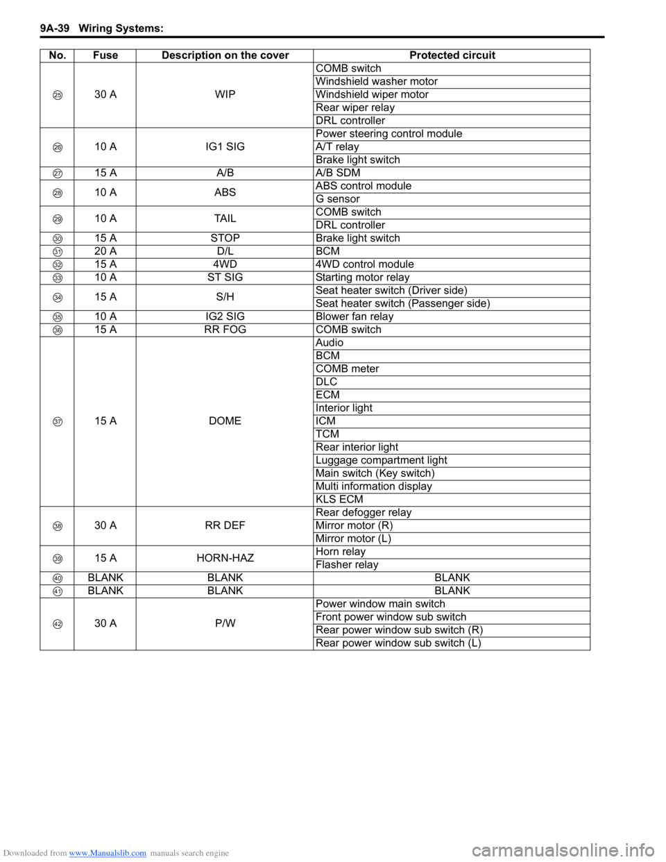
30 A WIPCOMB switch
Windshield washer motor
Windshield wiper motor
Rear wiper relay
DRL controller
10 A IG1 SIGPower steering control module
A/T relay
Brake light switch
15 A A/B A/B SDM
10 A ABSABS control module
G sensor
10 A TAILCOMB switch
DRL controller
15 A STOP Brake light switch
20 A D/L BCM
15 A 4WD 4WD control module
10 A ST SIG Starting motor relay
15 A S/HSeat heater switch (Driver side)
Seat heater switch (Passenger side)
10 A IG2 SIG Blower fan relay
15 A RR FOG COMB switch
15 A DOMEAudio
BCM
COMB meter
DLC
ECM
Interior light
ICM
TCM
Rear interior light
Luggage compartment light
Main switch (Key switch)
Multi information display
KLS ECM
30 A RR DEFRear defogger relay
Mirror motor (R)
Mirror motor (L)
15 A HORN-HAZHorn relay
Flasher relay
BLANK BLANK BLANK
BLANK BLANK BLANK
30 A P/WPower window main switch
Front power window sub switch
Rear power window sub switch (R)
Rear power window sub switch (L) No. Fuse Description on the cover Protected circuit
Page 1208 of 1556

Downloaded from www.Manualslib.com manuals search engine 9A-41 Wiring Systems:
10 A ABSABS control module
G sensor
BLANK BLANK BLANK
15 A STOP Brake light switch
20 A D/L BCM
BLANK BLANK BLANK
10 A ST SIG Starting motor relay
BLANK BLANK BLANK
10 A IG2 SIG Blower fan relay
10 A TAIL Tail light relay
15 A DOMEAudio
BCM
COMB meter
DLC
ECM
Interior light
ICM
TCM
Rear interior light
Luggage compartment light
Main switch (Key switch)
Multi information display
KLS ECM
30 A RR DEFRear defogger relay
Mirror motor (R)
Mirror motor (L)
15 A HORN-HAZHorn relay
Flasher relay
BLANK BLANK BLANK
BLANK BLANK BLANK
30 A P/WPower window main switch
Front power window sub switch
Rear power window sub switch (R)
Rear power window sub switch (L) No. Fuse Description on the cover Protected circuit
Page 1224 of 1556

Downloaded from www.Manualslib.com manuals search engine 9A-57 Wiring Systems:
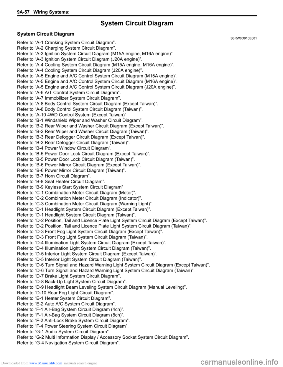
System Circuit Diagram
System Circuit DiagramS6RW0D910E001
Refer to “A-1 Cranking System Circuit Diagram”.
Refer to “A-2 Charging System Circuit Diagram”.
Refer to “A-3 Ignition System Circuit Diagram (M15A engine, M16A engine)”.
Refer to “A-3 Ignition System Circuit Diagram (J20A engine)”.
Refer to “A-4 Cooling System Circuit Diagram (M15A engine, M16A engine)”.
Refer to “A-4 Cooling System Circuit Diagram (J20A engine)”.
Refer to “A-5 Engine and A/C Control System Circuit Diagram (M15A engine)”.
Refer to “A-5 Engine and A/C Control System Circuit Diagram (M16A engine)”.
Refer to “A-5 Engine and A/C Control System Circuit Diagram (J20A engine)”.
Refer to “A-6 A/T Control System Circuit Diagram”.
Refer to “A-7 Immobilizer System Circuit Diagram”.
Refer to “A-8 Body Control System Circuit Diagram (Except Taiwan)”.
Refer to “A-8 Body Control System Circuit Diagram (Taiwan)”.
Refer to “A-10 4WD Control System (Except Taiwan)”
Refer to “B-1 Windshield Wiper and Washer Circuit Diagram”.
Refer to “B-2 Rear Wiper and Washer Circuit Diagram (Except Taiwan)”.
Refer to “B-2 Rear Wiper and Washer Circuit Diagram (Taiwan)”.
Refer to “B-3 Rear Defogger Circuit Diagram (Except Taiwan)”.
Refer to “B-3 Rear Defogger Circuit Diagram (Taiwan)”.
Refer to “B-4 Power Window Circuit Diagram”.
Refer to “B-5 Power Door Lock Circuit Diagram (Except Taiwan)”.
Refer to “B-5 Power Door Lock Circuit Diagram (Taiwan)”.
Refer to “B-6 Power Mirror Circuit Diagram (Except Taiwan)”.
Refer to “B-6 Power Mirror Circuit Diagram (Taiwan)”.
Refer to “B-7 Horn Circuit Diagram”.
Refer to “B-8 Seat Heater Circuit Diagram”.
Refer to “B-9 Keyless Start System Circuit Diagram”
Refer to “C-1 Combination Meter Circuit Diagram (Meter)”.
Refer to “C-2 Combination Meter Circuit Diagram (Indicator)”.
Refer to “C-3 Combination Meter Circuit Diagram (Warning Light)”.
Refer to “D-1 Headlight System Circuit Diagram (Except Taiwan)”.
Refer to “D-1 Headlight System Circuit Diagram (Taiwan)”.
Refer to “D-2 Position, Tail and Licence Plate Light System Circuit Diagram (Except Taiwan)”.
Refer to “D-2 Position, Tail and Licence Plate Light System Circuit Diagram (Taiwan)”.
Refer to “D-3 Front Fog Light System Circuit Diagram (Except Taiwan)”.
Refer to “D-3 Front Fog Light System Circuit Diagram (Taiwan)”.
Refer to “D-4 Illumination Light System Circuit Diagram (Except Taiwan)”.
Refer to “D-4 Illumination Light System Circuit Diagram (Taiwan)”.
Refer to “D-5 Interior Light System Circuit Diagram (Except Taiwan)”.
Refer to “D-5 Interior Light System Circuit Diagram (Taiwan)”.
Refer to “D-6 Turn Signal and Hazard Warning Light System Circuit Diagram (Except Taiwan)”.
Refer to “D-6 Turn Signal and Hazard Warning Light System Circuit Diagram (Taiwan)”.
Refer to “D-7 Brake Light System Circuit Diagram”.
Refer to “D-8 Back-Up Light System Circuit Diagram”.
Refer to “D-9 Headlight Beam Leveling System Circuit Diagram (Manual Leveling)”.
Refer to “D-10 Rear Fog Light Circuit Diagram”.
Refer to “E-1 Heater System Circuit Diagram”.
Refer to “E-2 Auto A/C System Circuit Diagram”.
Refer to “F-1 Air-Bag System Circuit Diagram (4ch)”.
Refer to “F-1 Air-Bag System Circuit Diagram (8ch)”.
Refer to “F-2 Anti-Lock Brake System Circuit Diagram”.
Refer to “F-4 Power Steering System Circuit Diagram”.
Refer to “G-1 Audio System Circuit Diagram”.
Refer to “G-2 Multi Information Display / Accessory Socket System Circuit Diagram”.
Refer to “G-4 Navigation System Circuit Diagram”.
Page 1233 of 1556

Downloaded from www.Manualslib.com manuals search engine Wiring Systems: 9A-66
Weld spliceC311
CKP
sensor
3C31
51
PNKBLK/ORN
BLK/RED
12
GW
J/B
2
15ASTOP
30
15ADOME
37
E0120
GRN/WHT
GRN/WHT
GRN
E3234
E181
Brake
light
switch
1 2
ECM
2
CMP
sensor
C01 C01
BLK
BLK
BLK
3463
1529 3031
1C32
52C01 E0122302813
RED/YEL
BLK/ORNBLKBLKBLKBLK
BLK/REDBLK/RED
32
J/B
E3251
2
YG
YEL/GRNYEL/BLKWHT/REDWHTYEL/RED
Starting
motor
relayICM
"A-7"YBYR
BR
2
W"A-1"
Starting
motor
relay
"A-1"
VSS
"A-6"
C343
E3711
I6RW0C910938-02
Page 1237 of 1556

Downloaded from www.Manualslib.com manuals search engine Wiring Systems: 9A-70
Weld spliceC311
GW
J/B
2
15ASTOP
30
15ADOME
37
E0120
GRN/WHT
GRN/WHT
GRN
E3234
E181
Brake
light
switch
1 2
ECM
2
CMP
sensor
C01
BLK
36
1531 30
1or3C32
20C01 E0148302813
RED/YEL
BLK/ORNBLK/ORN
BLK/ORN
BLKBLKBLK
C01 E0158
BLK/RED
3or2 2or1
J/B
E3251
2
YG
YEL/GRNYEL/BLKWHT/REDWHTYEL/RED
Starting
motor
relay Starting
motor
relay
"A-1"ICM
"A-7"YBYR
2
W"A-1"
CKP
sensor
3C31
21
PNKBLK/ORN
BLK/RED
12
Weld
splice
C313
I6RW0C910943-02