Exhaust System SUZUKI SX4 2006 1.G Service Workshop Manual
[x] Cancel search | Manufacturer: SUZUKI, Model Year: 2006, Model line: SX4, Model: SUZUKI SX4 2006 1.GPages: 1556, PDF Size: 37.31 MB
Page 5 of 1556
Downloaded from www.Manualslib.com manuals search engine 00
0
1
2
3
4
5
6
7
8
9
10
11
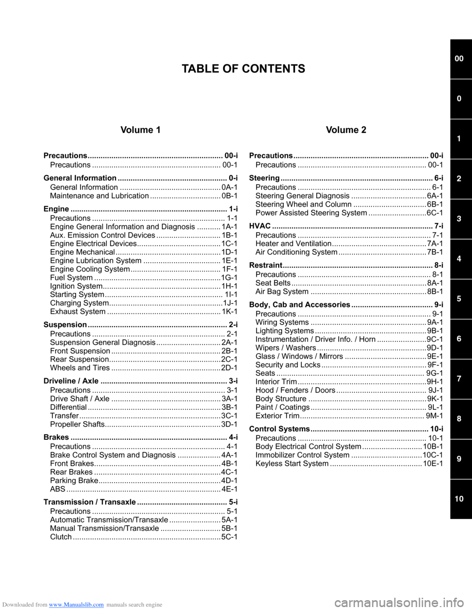
Vo l u m e 1
Precautions............................................................... 00-i
Precautions ............................................................ 00-1
General Information ................................................... 0-i
General Information ............................................... 0A-1
Maintenance and Lubrication ................................. 0B-1
Engine ......................................................................... 1-i
Precautions .............................................................. 1-1
Engine General Information and Diagnosis ........... 1A-1
Aux. Emission Control Devices .............................. 1B-1
Engine Electrical Devices....................................... 1C-1
Engine Mechanical ................................................. 1D-1
Engine Lubrication System .................................... 1E-1
Engine Cooling System .......................................... 1F-1
Fuel System ...........................................................1G-1
Ignition System....................................................... 1H-1
Starting System ....................................................... 1I-1
Charging System.....................................................1J-1
Exhaust System ..................................................... 1K-1
Suspension ................................................................. 2-i
Precautions .............................................................. 2-1
Suspension General Diagnosis .............................. 2A-1
Front Suspension ................................................... 2B-1
Rear Suspension.................................................... 2C-1
Wheels and Tires ................................................... 2D-1
Driveline / Axle ........................................................... 3-i
Precautions .............................................................. 3-1
Drive Shaft / Axle ................................................... 3A-1
Differential .............................................................. 3B-1
Transfer .................................................................. 3C-1
Propeller Shafts...................................................... 3D-1
Brakes ......................................................................... 4-i
Precautions .............................................................. 4-1
Brake Control System and Diagnosis .................... 4A-1
Front Brakes........................................................... 4B-1
Rear Brakes ........................................................... 4C-1
Parking Brake......................................................... 4D-1
ABS ........................................................................ 4E-1
Transmission / Transaxle .......................................... 5-i
Precautions .............................................................. 5-1
Automatic Transmission/Transaxle ........................ 5A-1
Manual Transmission/Transaxle ............................ 5B-1
Clutch ..................................................................... 5C-1
Vo l u m e 2
Precautions ............................................................... 00-i
Precautions ............................................................ 00-1
Steering ....................................................................... 6-i
Precautions .............................................................. 6-1
Steering General Diagnosis ................................... 6A-1
Steering Wheel and Column .................................. 6B-1
Power Assisted Steering System ...........................6C-1
HVAC ........................................................................... 7-i
Precautions .............................................................. 7-1
Heater and Ventilation............................................ 7A-1
Air Conditioning System ......................................... 7B-1
Restraint ...................................................................... 8-i
Precautions .............................................................. 8-1
Seat Belts ............................................................... 8A-1
Air Bag System ...................................................... 8B-1
Body, Cab and Accessories ...................................... 9-i
Precautions .............................................................. 9-1
Wiring Systems ...................................................... 9A-1
Lighting Systems .................................................... 9B-1
Instrumentation / Driver Info. / Horn .......................9C-1
Wipers / Washers ...................................................9D-1
Glass / Windows / Mirrors ...................................... 9E-1
Security and Locks ................................................. 9F-1
Seats ..................................................................... 9G-1
Interior Trim ............................................................9H-1
Hood / Fenders / Doors .......................................... 9J-1
Body Structure ....................................................... 9K-1
Paint / Coatings ...................................................... 9L-1
Exterior Trim .......................................................... 9M-1
Control Systems ....................................................... 10-i
Precautions ............................................................ 10-1
Body Electrical Control System ............................ 10B-1
Immobilizer Control System .................................10C-1
Keyless Start System ........................................... 10E-1
TABLE OF CONTENTS
Page 11 of 1556
Downloaded from www.Manualslib.com manuals search engine Precautions: 00-4
WARNING!
• Whenever raising a vehicle for service, be
sure to follow the instructions under
“Vehicle Lifting Points in Section 0A”.
• When it is necessary to do service work
with the engine running, make sure that
the parking brake is set fully and the
transmission is in Neutral (for manual
transmission vehicles) or Park (for
automatic transmission vehicles), Keep
hands, hair, clothing, tools, etc. away from
the fan and belts when the engine is
running.
• When it is necessary to run the engine
indoors, make sure that the exhaust gas is
forced outdoors.
• Do not perform service work in areas
where combustible materials can come in
contact with a hot exhaust system. When
working with toxic or flammable materials
(such as gasoline and refrigerant), make
sure that the area you work in is well-
ventilated.
• To avoid getting burned, keep away from
hot metal parts such as the radiator,
exhaust manifold, tail pipe, muffler, etc.
• New and used engine oil can be
hazardous. Children and pets may be
harmed by swallowing new or used oil.
Keep new and used oil and used engine oil
filters away from children and pets.
Continuous contact with used engine oil
has been found to cause [skin] cancer in
laboratory animals. Brief contact with used
oil may irritate skin. To minimize your
exposure to used engine oil, wear a long-
sleeve shirt and moisture-proof gloves
(such as dish washing gloves) when
changing engine oil. If engine oil contacts
your skin, wash thoroughly with soap and
water. Launder any clothing or rags if wet
with oil, recycle or properly dispose of
used oil and filters.
• Be sure to observe following instructions
when handling service materials such as
fuel, oil, fluid, coolant, grease, sealant,
thread lock cement, etc. Otherwise, your
health may be ruined.
– Whenever handling any of these service
materials, wear safety glasses to protect
your eyes. If it gets into your eye, it may
cause inflammation.
– Whenever handling any of these service
materials, wear moisture-proof gloves to
protect your skin. If it adheres to your
skin, it may cause inflammation.– Do not swallow any of these service
materials. It would cause diarrhea or
nausea.
– Keep all these materials out of children’s
reach.
• Make sure the bonnet is fully closed and
latched before driving. If it is not, it can fly
up unexpectedly during driving,
obstructing your view and resulting in an
accident.
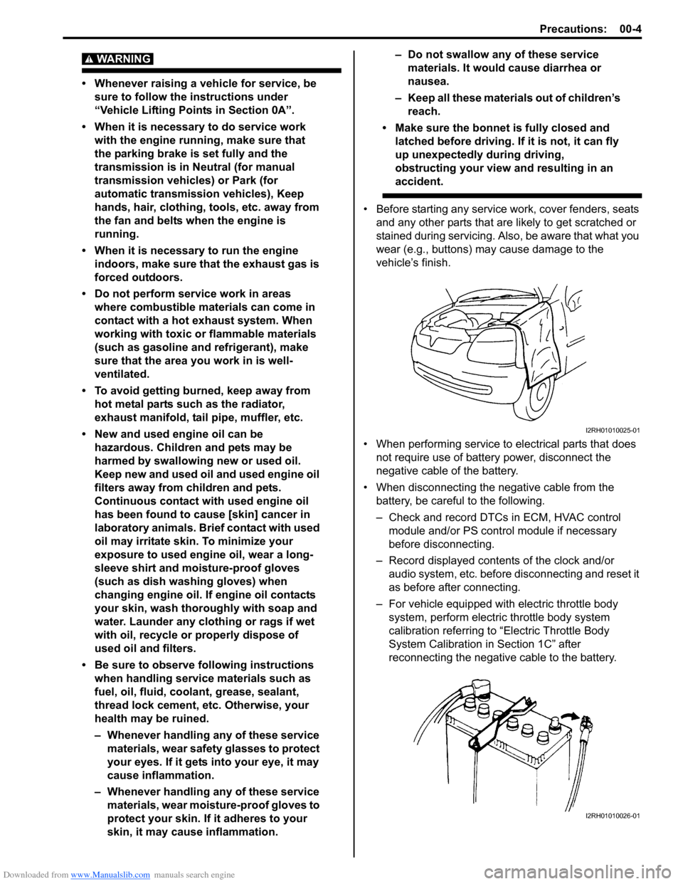
• Before starting any service work, cover fenders, seats
and any other parts that are likely to get scratched or
stained during servicing. Also, be aware that what you
wear (e.g., buttons) may cause damage to the
vehicle’s finish.
• When performing service to electrical parts that does
not require use of battery power, disconnect the
negative cable of the battery.
• When disconnecting the negative cable from the
battery, be careful to the following.
– Check and record DTCs in ECM, HVAC control
module and/or PS control module if necessary
before disconnecting.
– Record displayed contents of the clock and/or
audio system, etc. before disconnecting and reset it
as before after connecting.
– For vehicle equipped with electric throttle body
system, perform electric throttle body system
calibration referring to “Electric Throttle Body
System Calibration in Section 1C” after
reconnecting the negative cable to the battery.
I2RH01010025-01
I2RH01010026-01
Page 13 of 1556
Downloaded from www.Manualslib.com manuals search engine Precautions: 00-6
• After servicing fuel, oil, coolant, vacuum, exhaust or
brake systems, check all lines related to the system
for leaks.
• For vehicles equipped with fuel injection systems,
never disconnect the fuel line between the fuel pump
and injector without first releasing the fuel pressure, or
fuel can be sprayed out under pressure.
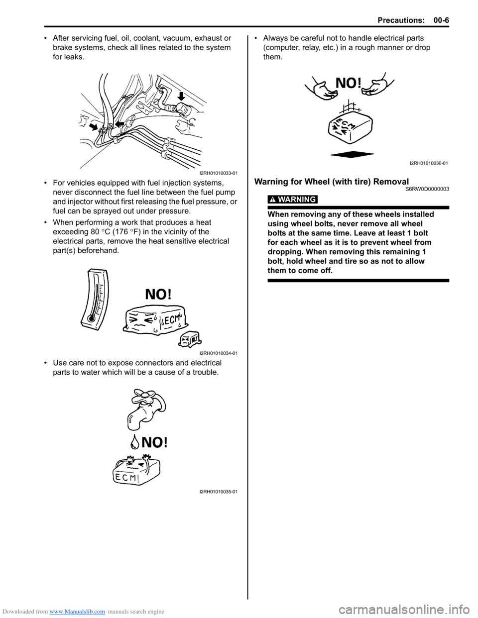
• When performing a work that produces a heat
exceeding 80 °C (176 °F) in the vicinity of the
electrical parts, remove the heat sensitive electrical
part(s) beforehand.
• Use care not to expose connectors and electrical
parts to water which will be a cause of a trouble.• Always be careful not to handle electrical parts
(computer, relay, etc.) in a rough manner or drop
them.
Warning for Wheel (with tire) RemovalS6RW0D0000003
WARNING!
When removing any of these wheels installed
using wheel bolts, never remove all wheel
bolts at the same time. Leave at least 1 bolt
for each wheel as it is to prevent wheel from
dropping. When removing this remaining 1
bolt, hold wheel and tire so as not to allow
them to come off.
I2RH01010033-01
I2RH01010034-01
I2RH01010035-01
I2RH01010036-01
Page 23 of 1556
Downloaded from www.Manualslib.com manuals search engine Table of Contents 0- i
0
Section 0
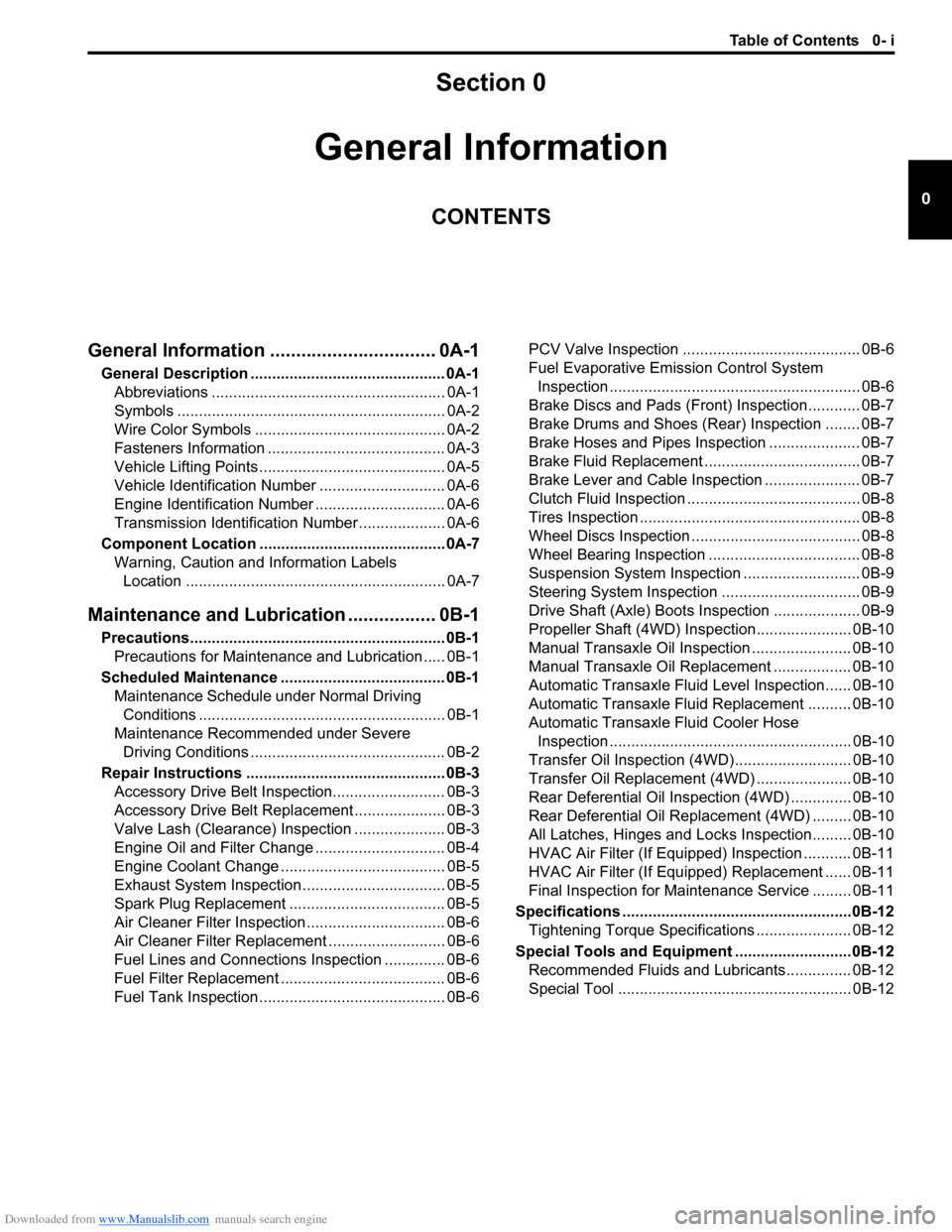
CONTENTS
General Information
General Information ................................ 0A-1
General Description ............................................. 0A-1
Abbreviations ...................................................... 0A-1
Symbols .............................................................. 0A-2
Wire Color Symbols ............................................ 0A-2
Fasteners Information ......................................... 0A-3
Vehicle Lifting Points ........................................... 0A-5
Vehicle Identification Number ............................. 0A-6
Engine Identification Number .............................. 0A-6
Transmission Identification Number .................... 0A-6
Component Location ........................................... 0A-7
Warning, Caution and Information Labels
Location ............................................................ 0A-7
Maintenance and Lubrication ................. 0B-1
Precautions........................................................... 0B-1
Precautions for Maintenance and Lubrication ..... 0B-1
Scheduled Maintenance ...................................... 0B-1
Maintenance Schedule under Normal Driving
Conditions ......................................................... 0B-1
Maintenance Recommended under Severe
Driving Conditions ............................................. 0B-2
Repair Instructions .............................................. 0B-3
Accessory Drive Belt Inspection.......................... 0B-3
Accessory Drive Belt Replacement ..................... 0B-3
Valve Lash (Clearance) Inspection ..................... 0B-3
Engine Oil and Filter Change .............................. 0B-4
Engine Coolant Change ...................................... 0B-5
Exhaust System Inspection ................................. 0B-5
Spark Plug Replacement .................................... 0B-5
Air Cleaner Filter Inspection ................................ 0B-6
Air Cleaner Filter Replacement ........................... 0B-6
Fuel Lines and Connections Inspection .............. 0B-6
Fuel Filter Replacement ...................................... 0B-6
Fuel Tank Inspection ........................................... 0B-6PCV Valve Inspection ......................................... 0B-6
Fuel Evaporative Emission Control System
Inspection .......................................................... 0B-6
Brake Discs and Pads (Front) Inspection............ 0B-7
Brake Drums and Shoes (Rear) Inspection ........ 0B-7
Brake Hoses and Pipes Inspection ..................... 0B-7
Brake Fluid Replacement .................................... 0B-7
Brake Lever and Cable Inspection ...................... 0B-7
Clutch Fluid Inspection ........................................ 0B-8
Tires Inspection ................................................... 0B-8
Wheel Discs Inspection ....................................... 0B-8
Wheel Bearing Inspection ................................... 0B-8
Suspension System Inspection ........................... 0B-9
Steering System Inspection ................................ 0B-9
Drive Shaft (Axle) Boots Inspection .................... 0B-9
Propeller Shaft (4WD) Inspection...................... 0B-10
Manual Transaxle Oil Inspection ....................... 0B-10
Manual Transaxle Oil Replacement .................. 0B-10
Automatic Transaxle Fluid Level Inspection...... 0B-10
Automatic Transaxle Fluid Replacement .......... 0B-10
Automatic Transaxle Fluid Cooler Hose
Inspection ........................................................ 0B-10
Transfer Oil Inspection (4WD)........................... 0B-10
Transfer Oil Replacement (4WD) ...................... 0B-10
Rear Deferential Oil Inspection (4WD) .............. 0B-10
Rear Deferential Oil Replacement (4WD) ......... 0B-10
All Latches, Hinges and Locks Inspection......... 0B-10
HVAC Air Filter (If Equipped) Inspection ........... 0B-11
HVAC Air Filter (If Equipped) Replacement ...... 0B-11
Final Inspection for Maintenance Service ......... 0B-11
Specifications .....................................................0B-12
Tightening Torque Specifications ...................... 0B-12
Special Tools and Equipment ...........................0B-12
Recommended Fluids and Lubricants............... 0B-12
Special Tool ...................................................... 0B-12
Page 24 of 1556
Downloaded from www.Manualslib.com manuals search engine 0A-1 General Information:
General Information
General Information
General Description
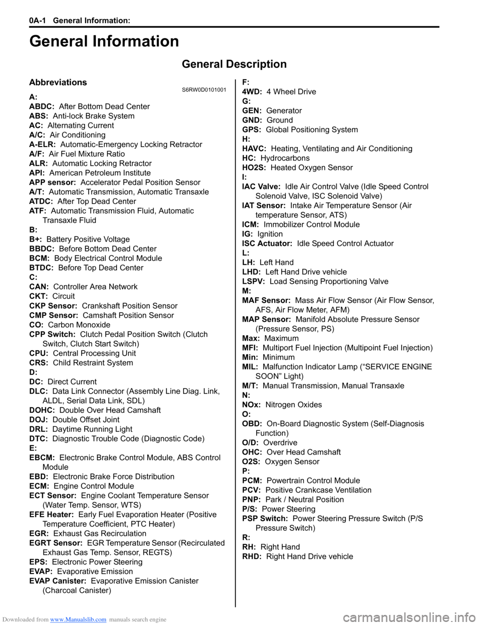
AbbreviationsS6RW0D0101001
A:
ABDC: After Bottom Dead Center
ABS: Anti-lock Brake System
AC: Alternating Current
A/C: Air Conditioning
A-ELR: Automatic-Emergency Locking Retractor
A/F: Air Fuel Mixture Ratio
ALR: Automatic Locking Retractor
API: American Petroleum Institute
APP sensor: Accelerator Pedal Position Sensor
A/T: Automatic Transmission, Automatic Transaxle
AT D C : After Top Dead Center
ATF: Automatic Transmission Fluid, Automatic
Transaxle Fluid
B:
B+: Battery Positive Voltage
BBDC: Before Bottom Dead Center
BCM: Body Electrical Control Module
BTDC: Before Top Dead Center
C:
CAN: Controller Area Network
CKT: Circuit
CKP Sensor: Crankshaft Position Sensor
CMP Sensor: Camshaft Position Sensor
CO: Carbon Monoxide
CPP Switch: Clutch Pedal Position Switch (Clutch
Switch, Clutch Start Switch)
CPU: Central Processing Unit
CRS: Child Restraint System
D:
DC: Direct Current
DLC: Data Link Connector (Assembly Line Diag. Link,
ALDL, Serial Data Link, SDL)
DOHC: Double Over Head Camshaft
DOJ: Double Offset Joint
DRL: Daytime Running Light
DTC: Diagnostic Trouble Code (Diagnostic Code)
E:
EBCM: Electronic Brake Control Module, ABS Control
Module
EBD: Electronic Brake Force Distribution
ECM: Engine Control Module
ECT Sensor: Engine Coolant Temperature Sensor
(Water Temp. Sensor, WTS)
EFE Heater: Early Fuel Evaporation Heater (Positive
Temperature Coefficient, PTC Heater)
EGR: Exhaust Gas Recirculation
EGRT Sensor: EGR Temperature Sensor (Recirculated
Exhaust Gas Temp. Sensor, REGTS)
EPS: Electronic Power Steering
EVAP: Evaporative Emission
EVAP Canister: Evaporative Emission Canister
(Charcoal Canister)F:
4WD: 4 Wheel Drive
G:
GEN: Generator
GND: Ground
GPS: Global Positioning System
H:
HAVC: Heating, Ventilating and Air Conditioning
HC: Hydrocarbons
HO2S: Heated Oxygen Sensor
I:
IAC Valve: Idle Air Control Valve (Idle Speed Control
Solenoid Valve, ISC Solenoid Valve)
IAT Sensor: Intake Air Temperature Sensor (Air
temperature Sensor, ATS)
ICM: Immobilizer Control Module
IG: Ignition
ISC Actuator: Idle Speed Control Actuator
L:
LH: Left Hand
LHD: Left Hand Drive vehicle
LSPV: Load Sensing Proportioning Valve
M:
MAF Sensor: Mass Air Flow Sensor (Air Flow Sensor,
AFS, Air Flow Meter, AFM)
MAP Sensor: Manifold Absolute Pressure Sensor
(Pressure Sensor, PS)
Max: Maximum
MFI: Multiport Fuel Injection (Multipoint Fuel Injection)
Min: Minimum
MIL: Malfunction Indicator Lamp (“SERVICE ENGINE
SOON” Light)
M/T: Manual Transmission, Manual Transaxle
N:
NOx: Nitrogen Oxides
O:
OBD: On-Board Diagnostic System (Self-Diagnosis
Function)
O/D: Overdrive
OHC: Over Head Camshaft
O2S: Oxygen Sensor
P:
PCM: Powertrain Control Module
PCV: Positive Crankcase Ventilation
PNP: Park / Neutral Position
P/S: Power Steering
PSP Switch: Power Steering Pressure Switch (P/S
Pressure Switch)
R:
RH: Right Hand
RHD: Right Hand Drive vehicle
Page 32 of 1556
Downloaded from www.Manualslib.com manuals search engine 0B-1 Maintenance and Lubrication:
General Information
Maintenance and Lubrication
Precautions
Precautions for Maintenance and LubricationS6RW0D0200001
Air Bag Warning
Refer to “Air Bag Warning in Section 00”.
Scheduled Maintenance
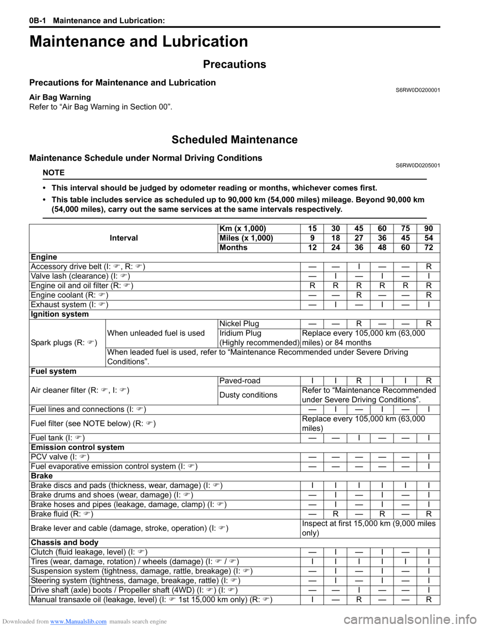
Maintenance Schedule under Normal Driving ConditionsS6RW0D0205001
NOTE
• This interval should be judged by odometer reading or months, whichever comes first.
• This table includes service as scheduled up to 90,000 km (54,000 miles) mileage. Beyond 90,000 km
(54,000 miles), carry out the same services at the same intervals respectively.
IntervalKm (x 1,000) 15 30 45 60 75 90
Miles (x 1,000) 9 18 27 36 45 54
Months 12 24 36 48 60 72
Engine
Accessory drive belt (I: �), R: �))——I——R
Valve lash (clearance) (I: �))—I—I—I
Engine oil and oil filter (R: �)) RRRRRR
Engine coolant (R: �))——R——R
Exhaust system (I: �))—I—I—I
Ignition system
Spark plugs (R: �))When unleaded fuel is usedNickel Plug — — R — — R
Iridium Plug
(Highly recommended)Replace every 105,000 km (63,000
miles) or 84 months
When leaded fuel is used, refer to “Maintenance Recommended under Severe Driving
Conditions”.
Fuel system
Air cleaner filter (R: �), I: �))Paved-road I I R I I R
Dusty conditionsRefer to “Maintenance Recommended
under Severe Driving Conditions”.
Fuel lines and connections (I: �))—I—I—I
Fuel filter (see NOTE below) (R: �))Replace every 105,000 km (63,000
miles)
Fuel tank (I: �))——I——I
Emission control system
PCV valve (I: �)) ————— I
Fuel evaporative emission control system (I: �)) ————— I
Brake
Brake discs and pads (thickness, wear, damage) (I: �)) IIIIII
Brake drums and shoes (wear, damage) (I: �))—I—I—I
Brake hoses and pipes (leakage, damage, clamp) (I: �))—I—I—I
Brake fluid (R: �))—R—R—R
Brake lever and cable (damage, stroke, operation) (I: �))Inspect at first 15,000 km (9,000 miles
only)
Chassis and body
Clutch (fluid leakage, level) (I: �))—I—I—I
Tires (wear, damage, rotation) / wheels (damage) (I: �) / �)) IIIIII
Suspension system (tightness, damage, rattle, breakage) (I: �))—I—I—I
Steering system (tightness, damage, breakage, rattle) (I: �))—I—I—I
Drive shaft (axle) boots / Propeller shaft (4WD) (I: �)) (I: �))——I——I
Manual transaxle oil (leakage, level) (I: �) 1st 15,000 km only) (R: �))I—R——R
Page 36 of 1556
Downloaded from www.Manualslib.com manuals search engine 0B-5 Maintenance and Lubrication:
6) Replenish oil until oil level is brought to FULL level
mark on dipstick (oil pan and oil filter capacity). The
filler inlet is at the top of the cylinder head cover. It is
recommended to use engine oil of SG, SH, SJ, SL or
SM grade. Select the appropriate oil viscosity
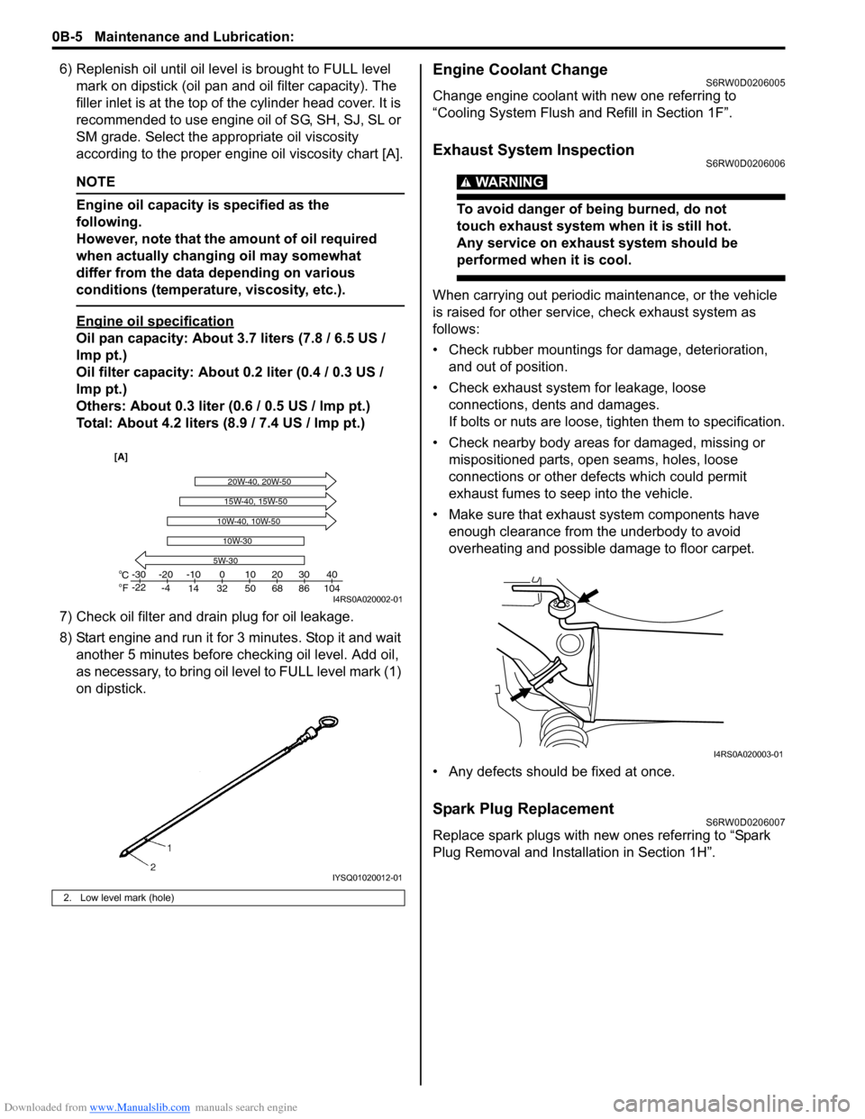
according to the proper engine oil viscosity chart [A].
NOTE
Engine oil capacity is specified as the
following.
However, note that the amount of oil required
when actually changing oil may somewhat
differ from the data depending on various
conditions (temperature, viscosity, etc.).
Engine oil specification
Oil pan capacity: About 3.7 liters (7.8 / 6.5 US /
lmp pt.)
Oil filter capacity: About 0.2 liter (0.4 / 0.3 US /
lmp pt.)
Others: About 0.3 liter (0.6 / 0.5 US / lmp pt.)
Total: About 4.2 liters (8.9 / 7.4 US / lmp pt.)
7) Check oil filter and drain plug for oil leakage.
8) Start engine and run it for 3 minutes. Stop it and wait
another 5 minutes before checking oil level. Add oil,
as necessary, to bring oil level to FULL level mark (1)
on dipstick.
Engine Coolant ChangeS6RW0D0206005
Change engine coolant with new one referring to
“Cooling System Flush and Refill in Section 1F”.
Exhaust System InspectionS6RW0D0206006
WARNING!
To avoid danger of being burned, do not
touch exhaust system when it is still hot.
Any service on exhaust system should be
performed when it is cool.
When carrying out periodic maintenance, or the vehicle
is raised for other service, check exhaust system as
follows:
• Check rubber mountings for damage, deterioration,
and out of position.
• Check exhaust system for leakage, loose
connections, dents and damages.
If bolts or nuts are loose, tighten them to specification.
• Check nearby body areas for damaged, missing or
mispositioned parts, open seams, holes, loose
connections or other defects which could permit
exhaust fumes to seep into the vehicle.
• Make sure that exhaust system components have
enough clearance from the underbody to avoid
overheating and possible damage to floor carpet.
• Any defects should be fixed at once.
Spark Plug ReplacementS6RW0D0206007
Replace spark plugs with new ones referring to “Spark
Plug Removal and Installation in Section 1H”.
2. Low level mark (hole)
C
Fo o-30
-22-20
-4-10
14 32 50 68 86 104010203040
5W-30
20W-40, 20W-50
10W-30
15W-40, 15W-50
10W-40, 10W-50
[A]
I4RS0A020002-01
IYSQ01020012-01
I4RS0A020003-01
Page 42 of 1556
Downloaded from www.Manualslib.com manuals search engine 0B-11 Maintenance and Lubrication:
HVAC Air Filter (If Equipped) InspectionS6RW0D0206034
Check HVAC air filter for dirt and dust referring to “HVAC
Air Filter Inspection (If Equipped) in Section 7A”. If air
filter is dirty, clean or replace air filter with new one.
HVAC Air Filter (If Equipped) ReplacementS6RW0D0206035
Replace HVAC air filter with new one referring to “HVAC
Air Filter Removal and Installation (If Equipped) in
Section 7A”.
Final Inspection for Maintenance ServiceS6RW0D0206036
WARNING!
When carrying out road tests, select a safe
place where no man or no running vehicle is
seen so as to prevent any accident.
Seats
Check that seat slides smoothly and locks securely at
any position. Also check that reclining mechanism of
front seat back allows it to be locked at any angle.
Seat Belt
Inspect belt system including webbing, buckles, latch
plates, retractors and anchors for damage or wear.
Check that seat belt is securely locked. If “REPLACE
BELT” label on seat belt is visible, replace belt.
Battery Electrolyte Level Check
Check that the electrolyte level of all battery cells is
between the upper and lower level lines on the case. If
battery is equipped with built-in indicator, check battery
condition by the indicator.
Accelerator Pedal Operation
Check that pedal operates smoothly without getting
caught or interfered by any other part.
Engine Start
Check engine start for readiness.
WARNING!
Before performing the following check, be
sure to have enough room around the
vehicle. Then, firmly apply both the parking
brake and the regular brakes. Do not use the
accelerator pedal. If the engine starts, be
ready to turn off the ignition promptly. Take
these precautions because the vehicle could
move without warning and possibly cause
personal injury or property damage.
On automatic transaxle vehicles, try to start the engine in
each select lever position. The starting motor should
crank only in “P” (Park) or “N” (Neutral).
On manual transaxle vehicles, place the shift lever in
“Neutral,” depress clutch pedal fully and try to start.
Exhaust System Check
Check for leakage, cracks or loose supports.
Clutch (for Manual Transaxle)
Check for the following.
• Clutch is completely released when depressing clutch
pedal,
• No slipping clutch occurs when releasing pedal and
accelerating.
• Clutch itself is free from any abnormal condition.
Gearshift or Select Lever
Check gear shift or select lever for smooth shifting to all
positions and for good performance of transaxle in any
position.
With automatic transaxle equipped vehicle, also check
that shift indicator indicates properly according to which
position select lever is shifted to.
With automatic transaxle equipped vehicle, make sure
that vehicle is at complete stop when shifting select lever
to “P” range position and release all brakes.
Brake
Foot brake
Check the following:
• that brake pedal has proper travel,
• that brake works properly,
• that it is free from noise,
• that vehicle does not pull to one side when brake is
applied.
• and that brake do not drag.
Parking brake
Check that lever has proper travel.
WARNING!
With vehicle parked on a fairly steep slope,
make sure nothing is in the way downhill to
avoid any personal injury or property
damage. Be prepared to apply regular brake
quickly even if vehicle should start to move.
Check to ensure that parking brake is fully effective
when the vehicle is stopped on the safe slope and brake
lever is pulled all the way.
Page 46 of 1556
Downloaded from www.Manualslib.com manuals search engine 1-ii Table of Contents
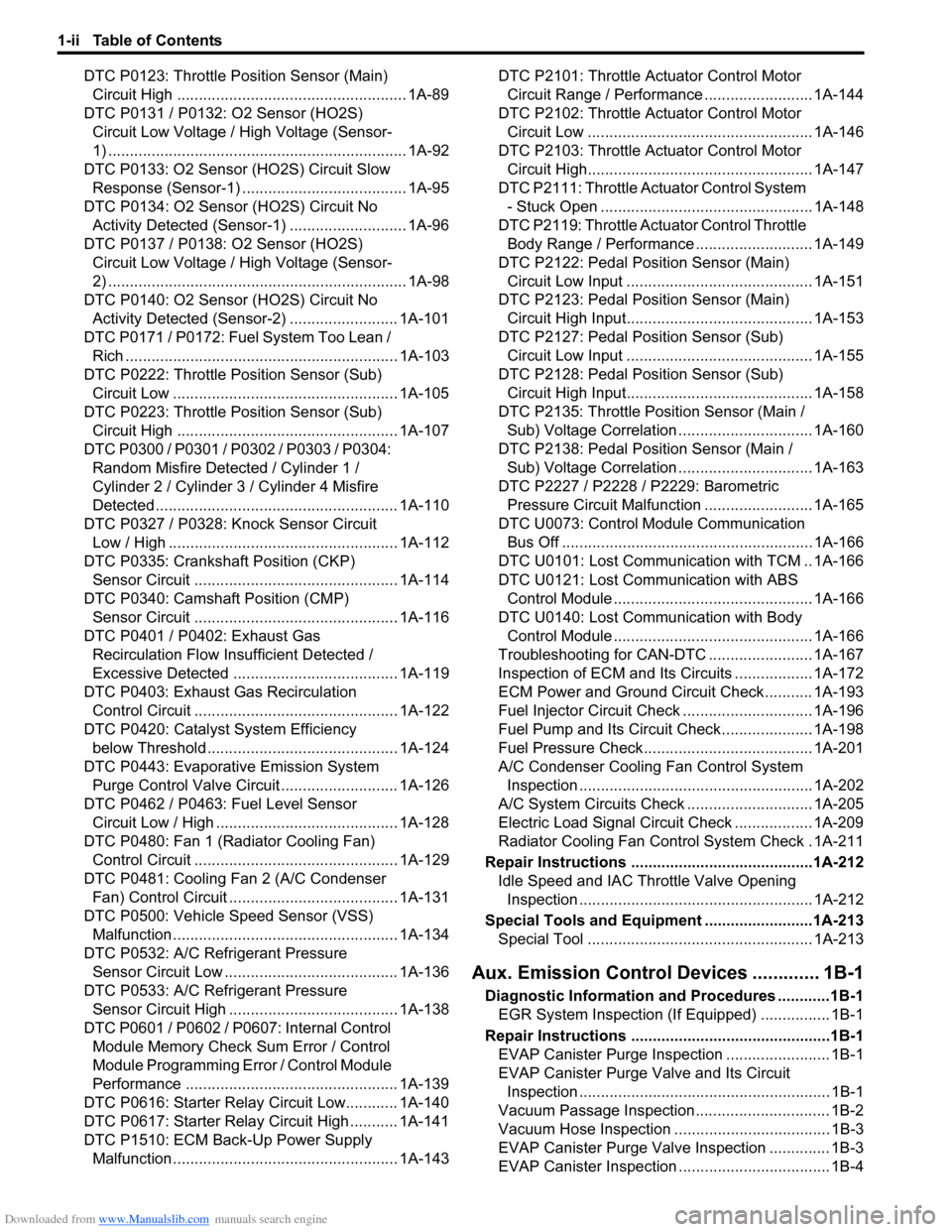
DTC P0123: Throttle Position Sensor (Main)
Circuit High ..................................................... 1A-89
DTC P0131 / P0132: O2 Sensor (HO2S)
Circuit Low Voltage / High Voltage (Sensor-
1) ..................................................................... 1A-92
DTC P0133: O2 Sensor (HO2S) Circuit Slow
Response (Sensor-1) ...................................... 1A-95
DTC P0134: O2 Sensor (HO2S) Circuit No
Activity Detected (Sensor-1) ........................... 1A-96
DTC P0137 / P0138: O2 Sensor (HO2S)
Circuit Low Voltage / High Voltage (Sensor-
2) ..................................................................... 1A-98
DTC P0140: O2 Sensor (HO2S) Circuit No
Activity Detected (Sensor-2) ......................... 1A-101
DTC P0171 / P0172: Fuel System Too Lean /
Rich ............................................................... 1A-103
DTC P0222: Throttle Position Sensor (Sub)
Circuit Low .................................................... 1A-105
DTC P0223: Throttle Position Sensor (Sub)
Circuit High ................................................... 1A-107
DTC P0300 / P0301 / P0302 / P0303 / P0304:
Random Misfire Detected / Cylinder 1 /
Cylinder 2 / Cylinder 3 / Cylinder 4 Misfire
Detected ........................................................ 1A-110
DTC P0327 / P0328: Knock Sensor Circuit
Low / High ..................................................... 1A-112
DTC P0335: Crankshaft Position (CKP)
Sensor Circuit ............................................... 1A-114
DTC P0340: Camshaft Position (CMP)
Sensor Circuit ............................................... 1A-116
DTC P0401 / P0402: Exhaust Gas
Recirculation Flow Insufficient Detected /
Excessive Detected ...................................... 1A-119
DTC P0403: Exhaust Gas Recirculation
Control Circuit ............................................... 1A-122
DTC P0420: Catalyst System Efficiency
below Threshold ............................................ 1A-124
DTC P0443: Evaporative Emission System
Purge Control Valve Circuit........................... 1A-126
DTC P0462 / P0463: Fuel Level Sensor
Circuit Low / High .......................................... 1A-128
DTC P0480: Fan 1 (Radiator Cooling Fan)
Control Circuit ............................................... 1A-129
DTC P0481: Cooling Fan 2 (A/C Condenser
Fan) Control Circuit ....................................... 1A-131
DTC P0500: Vehicle Speed Sensor (VSS)
Malfunction .................................................... 1A-134
DTC P0532: A/C Refrigerant Pressure
Sensor Circuit Low ........................................ 1A-136
DTC P0533: A/C Refrigerant Pressure
Sensor Circuit High ....................................... 1A-138
DTC P0601 / P0602 / P0607: Internal Control
Module Memory Check Sum Error / Control
Module Programming Error / Control Module
Performance ................................................. 1A-139
DTC P0616: Starter Relay Circuit Low............ 1A-140
DTC P0617: Starter Relay Circuit High ........... 1A-141
DTC P1510: ECM Back-Up Power Supply
Malfunction .................................................... 1A-143DTC P2101: Throttle Actuator Control Motor
Circuit Range / Performance ......................... 1A-144
DTC P2102: Throttle Actuator Control Motor
Circuit Low .................................................... 1A-146
DTC P2103: Throttle Actuator Control Motor
Circuit High.................................................... 1A-147
DTC P2111: Throttle Actuator Control System
- Stuck Open ................................................. 1A-148
DTC P2119: Throttle Actuator Control Throttle
Body Range / Performance ........................... 1A-149
DTC P2122: Pedal Position Sensor (Main)
Circuit Low Input ........................................... 1A-151
DTC P2123: Pedal Position Sensor (Main)
Circuit High Input........................................... 1A-153
DTC P2127: Pedal Position Sensor (Sub)
Circuit Low Input ........................................... 1A-155
DTC P2128: Pedal Position Sensor (Sub)
Circuit High Input........................................... 1A-158
DTC P2135: Throttle Position Sensor (Main /
Sub) Voltage Correlation ............................... 1A-160
DTC P2138: Pedal Position Sensor (Main /
Sub) Voltage Correlation ............................... 1A-163
DTC P2227 / P2228 / P2229: Barometric
Pressure Circuit Malfunction ......................... 1A-165
DTC U0073: Control Module Communication
Bus Off .......................................................... 1A-166
DTC U0101: Lost Communication with TCM .. 1A-166
DTC U0121: Lost Communication with ABS
Control Module .............................................. 1A-166
DTC U0140: Lost Communication with Body
Control Module .............................................. 1A-166
Troubleshooting for CAN-DTC ........................ 1A-167
Inspection of ECM and Its Circuits .................. 1A-172
ECM Power and Ground Circuit Check........... 1A-193
Fuel Injector Circuit Check .............................. 1A-196
Fuel Pump and Its Circuit Check..................... 1A-198
Fuel Pressure Check....................................... 1A-201
A/C Condenser Cooling Fan Control System
Inspection ...................................................... 1A-202
A/C System Circuits Check ............................. 1A-205
Electric Load Signal Circuit Check .................. 1A-209
Radiator Cooling Fan Control System Check . 1A-211
Repair Instructions ..........................................1A-212
Idle Speed and IAC Throttle Valve Opening
Inspection ...................................................... 1A-212
Special Tools and Equipment .........................1A-213
Special Tool .................................................... 1A-213
Aux. Emission Control Devices ............. 1B-1
Diagnostic Information and Procedures ............1B-1
EGR System Inspection (If Equipped) ................ 1B-1
Repair Instructions ..............................................1B-1
EVAP Canister Purge Inspection ........................ 1B-1
EVAP Canister Purge Valve and Its Circuit
Inspection .......................................................... 1B-1
Vacuum Passage Inspection............................... 1B-2
Vacuum Hose Inspection .................................... 1B-3
EVAP Canister Purge Valve Inspection .............. 1B-3
EVAP Canister Inspection ................................... 1B-4
Page 49 of 1556
Downloaded from www.Manualslib.com manuals search engine Table of Contents 1-v
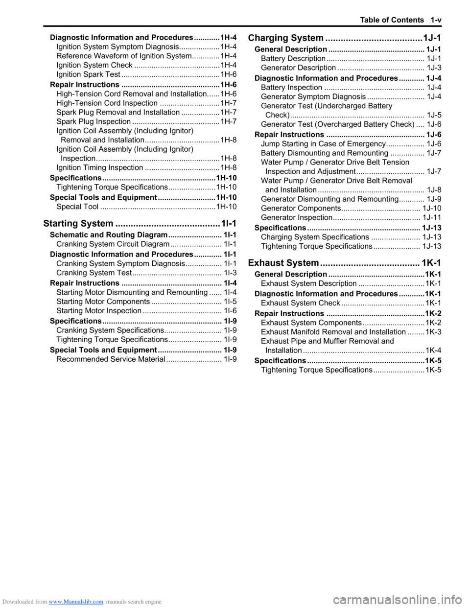
Diagnostic Information and Procedures ............ 1H-4
Ignition System Symptom Diagnosis................... 1H-4
Reference Waveform of Ignition System............. 1H-4
Ignition System Check ........................................ 1H-4
Ignition Spark Test .............................................. 1H-6
Repair Instructions .............................................. 1H-6
High-Tension Cord Removal and Installation...... 1H-6
High-Tension Cord Inspection ............................ 1H-7
Spark Plug Removal and Installation .................. 1H-7
Spark Plug Inspection ......................................... 1H-7
Ignition Coil Assembly (Including Ignitor)
Removal and Installation................................... 1H-8
Ignition Coil Assembly (Including Ignitor)
Inspection.......................................................... 1H-8
Ignition Timing Inspection ................................... 1H-8
Specifications..................................................... 1H-10
Tightening Torque Specifications ...................... 1H-10
Special Tools and Equipment ........................... 1H-10
Special Tool ...................................................... 1H-10
Starting System ......................................... 1I-1
Schematic and Routing Diagram ......................... 1I-1
Cranking System Circuit Diagram ........................ 1I-1
Diagnostic Information and Procedures ............. 1I-1
Cranking System Symptom Diagnosis ................. 1I-1
Cranking System Test.......................................... 1I-3
Repair Instructions ............................................... 1I-4
Starting Motor Dismounting and Remounting ...... 1I-4
Starting Motor Components ................................. 1I-5
Starting Motor Inspection ..................................... 1I-6
Specifications........................................................ 1I-9
Cranking System Specifications........................... 1I-9
Tightening Torque Specifications ......................... 1I-9
Special Tools and Equipment.............................. 1I-9
Recommended Service Material .......................... 1I-9
Charging System ...................................... 1J-1
General Description ............................................. 1J-1
Battery Description .............................................. 1J-1
Generator Description ......................................... 1J-3
Diagnostic Information and Procedures ............ 1J-4
Battery Inspection ............................................... 1J-4
Generator Symptom Diagnosis ........................... 1J-4
Generator Test (Undercharged Battery
Check) ............................................................... 1J-5
Generator Test (Overcharged Battery Check) .... 1J-6
Repair Instructions .............................................. 1J-6
Jump Starting in Case of Emergency.................. 1J-6
Battery Dismounting and Remounting ................ 1J-7
Water Pump / Generator Drive Belt Tension
Inspection and Adjustment ................................ 1J-7
Water Pump / Generator Drive Belt Removal
and Installation .................................................. 1J-8
Generator Dismounting and Remounting............ 1J-9
Generator Components..................................... 1J-10
Generator Inspection......................................... 1J-11
Specifications ..................................................... 1J-13
Charging System Specifications ....................... 1J-13
Tightening Torque Specifications ...................... 1J-13
Exhaust System ....................................... 1K-1
General Description .............................................1K-1
Exhaust System Description ............................... 1K-1
Diagnostic Information and Procedures ............1K-1
Exhaust System Check ....................................... 1K-1
Repair Instructions ..............................................1K-2
Exhaust System Components ............................. 1K-2
Exhaust Manifold Removal and Installation ........ 1K-3
Exhaust Pipe and Muffler Removal and
Installation ......................................................... 1K-4
Specifications .......................................................1K-5
Tightening Torque Specifications ........................ 1K-5