ESP TOYOTA AVALON 2020 (in English) User Guide
[x] Cancel search | Manufacturer: TOYOTA, Model Year: 2020, Model line: AVALON, Model: TOYOTA AVALON 2020Pages: 540, PDF Size: 10.4 MB
Page 73 of 540

731-2. Emergency assistance
1
For safety and security
■Safety Connect Services Information
●Phone calls using the vehicle’s Bluetooth® technology will not be possible
during Safety Connect.
● Safety Connect is available beginning Fall 2009 on select Toyot a models (in
the contiguous United States only). Contact with the Safety Con nect
response center is dependent upon the telematics device being i n operative
condition, cellular connection availability, and GPS satellite signal reception,
which can limit the ability to reach the response center or rec eive emer-
gency service support. Enrollment and Telematics Subscription S ervice
Agreement are required. A variety of subscription terms are ava ilable;
charges vary by subscription term selected and location.
● Automatic Collision Notification, Emergency Assistance and Stolen Vehicle
Location are available in the United States, including Hawaii a nd Alaska,
Puerto Rico and Canada, and Enhanced Roadside Assistance are av ailable
in the United States, Puerto Rico and Canada.
● Automatic Collision Notification, Emergency Assistance, Stolen Vehicle and
Enhanced Road Assistance are not available in the U.S. Virgin I slands.
For vehicles first sold in the U.S. Virgin Islands, no Safety C onnect services
will function in or outside the U.S. Virgin Islands.
● Safety Connect services are not subject to section 255 of the T elecommuni-
cations Act and the device is not TTY compatible.
■ Languages
The Safety Connect response center will offer support in multip le languages.
The Safety Connect system will offer voice prompts in English, Spanish, and
French. Please indicate your language of choice when enrolling.
■ When contacting the response center
You may be unable to contact the response center if the network is busy.
When the engine switch is turned to IGNITION ON mode, the red i ndi-
cator light comes on for 2 seconds then turns off. Afterward, t he green
indicator light comes on, indicat ing that the service is active.
The following indicator light patterns indicate specific system usage
conditions:
● Green indicator light on = Active service
● Green indicator light flashing = Safety Connect call in process
● Red indicator light (except at vehicle start-up) = System malfunction
(contact your Toyota dealer)
● No indicator light (off) = Saf ety Connect service not active
Safety Connect LED light Indicators
Page 74 of 540

741-2. Emergency assistance
■Automatic Collision Notification
In case of either airbag deployment or severe rear-end collision, the
system is designed to automatically call the response center. T he
responding agent receives the v ehicle’s location and attempts to
speak with the vehicl e occupants to assess the level of emergency.
If the occupants are unable to communicate, the agent automati-
cally treats the call as an emergency, contacts the nearest eme r-
gency services provider to descr ibe the situation, and requests that
assistance be sent to the location.
■Stolen Vehicle Location
If your vehicle is stolen, Safety Connect can work with local author-
ities to assist them in locating and recovering the vehicle. Af ter filing
a police report, call the Safety Connect response center at 1-8 55-
405-6500 in the United States, 1-877-855-8377 in Puerto Rico or 1-
888-869-6828 in Canada, and follow the prompts for Safety Con-
nect to initiate this service.
In addition to assisting law enforcement with recovery of a sto len
vehicle, Safety-Connect-equipped vehicle location data may, und er
certain circumstances, be shared with third parties to locate y our
vehicle. Further information is a vailable at Toyota.com in the United
States, Toyotapr.com in Puerto Rico and Toyota.ca in Canada.
■Emergency Assistance Button (“SOS”)
In the event of an emergency on t he road, push the “SOS” button to
reach the Safety Connect respons e center. The answering agent
will determine your vehicle’s loca tion, assess the emergency, and
dispatch the necessary assistanc e required.
If you accidentally press the “SOS” button, tell the response-c enter
agent that you are not experiencing an emergency.
Safety Connect services
Page 75 of 540

751-2. Emergency assistance
1
For safety and security
■Enhanced Roadside Assistance
Enhanced Roadside Assistance adds GPS data to the already
included warranty-based Toyota roadside service.
Subscribers can press the “SOS” button to reach a Safety Connec t
response-center agent, who can he lp with a wide range of needs,
such as: towing, flat tire, fuel delivery, etc. For a description of the
Enhanced Roadside Assistance se rvices and their limitations,
please see the Safety Connect Te rms and Conditions, which are
available at Toyota.com in the United States, Toyotapr.com in
Puerto Rico and Toyota.ca in Canada.
Important! Read this informatio n before using Safety Connect.
■Exposure to radio frequency signals
The Safety Connect system installed in your vehicle is a low-po wer
radio transmitter and receiver. I t receives and also sends out radio
frequency (RF) signals.
In August 1996, the Federal Communications Commission (FCC)
adopted RF exposure guidelines with safety levels for mobile wi re-
less phones. Those guidelines are consistent with the safety stan-
dards previously set by the following U.S. and international
standards bodies.
● ANSI (American National Stand ards Institute) C95.1 [1992]
● NCRP (National Council on Radi ation Protection and Measure-
ment) Report 86 [1986]
● ICNIRP (International Commission on Non-Ionizing Radiation
Protection) [1996]
Those standards were based on comprehensive and periodic eval-
uations of the relevant scienti fic literature. Over 120 scientists, engi-
neers, and physicians from unive rsities, and government health
agencies and industries reviewed the available body of research to
develop the ANSI Standard (C95.1).
The design of Safety Connect complies with the FCC guidelines i n
addition to those standards.
Safety information for Safety Connect
Page 106 of 540

1062. Instrument cluster
■Odometer
Displays the total distance the vehicle has been driven.
■Trip meter A/trip meter B
Displays the distance the vehicl e has been driven since the met er
was last reset. Trip meters A and B can be used to record and d is-
play different distances independently.
To reset, display the desired trip meter and press and hold the “ODO/
TRIP” switch.
Displays suggestions to the drive r in the following situations. To select
a response to a displayed suggestion, use the meter control swi tches.
The suggestion function can be turned on/off.
(Customizable features:P. 497)
■
Suggestion to turn off the headlights
If the headlights are left on for a certain amount of time afte r the
engine switch has been turned of f, if the headlight switch is in the
“AUTO” position, a suggestion m essage will be displayed asking if
you wish to turn the headlights off. To turn the headlights off , select
“Yes”.
If a front door is opened after the engine switch is turned off, this sug-
gestion message will not be displayed.
Odometer/trip meter
Suggestion function
Page 108 of 540

1082. Instrument cluster
WARNING
■Caution for use while driving
● When operating the multi-information display while driving, pay extra
attention to the safety of the area around the vehicle.
● Do not look continuously at the multi-information display while driving as
you may fail to see pedestrians, objects on the road, etc. ahea d of the
vehicle.
■ The information display at low temperatures
Allow the interior of the vehicle to warm up before using the liquid crystal
information display. At extremely low temperatures, the information display
monitor may respond slowly, and display changes may be delayed.
For example, there is a lag between the driver’s shifting and t he new gear
number appearing on the display. This lag could cause the drive r to down-
shift again, causing rapid and excessive engine braking and pos sibly an
accident resulting in death or injury.
■ Cautions during setting up the display
As the engine needs to be running during setting up the display , ensure that
the vehicle is parked in a place with adequate ventilation. In a closed area
such as a garage, exhaust gases including harmful carbon monoxi de (CO)
may collect and enter the vehicle. This may lead to death or a serious
health hazard.
NOTICE
■ While setting up the display
To prevent battery discharge, ensure that the engine is running while setting
up the display features.
Page 114 of 540

1142. Instrument cluster
■Head-up display
The head-up display may seem dark or hard to see when viewed th rough
sunglasses, especially polarized sunglasses.
Adjust the brightness of the head-up display or remove your sun glasses.
■ Display brightness
The brightness of the head-up display can be adjusted on of th e multi-
information display. Also, it is automatically adjusted accordi ng to the ambient
brightness.
■ Enabling/disabling of the head-up display
If the head-up display is disabled, it will remain disabled whe n the engine
switch is turned off then back to IGNITION ON mode.
■ Street name display
Only street names which are included in the map data will be displayed.
WARNING
■Before using the head-up display
● Check that the position and brightness of the head-up display i mage does
not interfere with safe driving. Incorrect adjustment of the image’s position
or brightness may obstruct the driver’s view and lead to an acc ident,
resulting in death or serious injury.
● Do not continuously look at the head-up display while driving a s you may
fail to see pedestrians, objects on the road, etc. ahead of the vehicle.
■ Caution for changing setti ngs of the head-up display
As the engine needs to be running while changing the settings of the head-
up display, ensure that the vehicle is parked in a place with adequate venti-
lation. In a closed area such as a garage, exhaust gases includ ing harmful
carbon monoxide (CO) may collect and enter the vehicle. This may lead to
death or a serious health hazard.
Page 130 of 540

1303-2. Opening, closing and locking the doors
■Using the mechanical key
The doors can also be locked and unlocked with the mechanical key.
(P. 459)
■ Conditions affecting the operation of the smart key system or w ireless
remote control
P. 137
■ Customization
Some functions can be customized. ( P. 497)
WARNING
■To prevent an accident
Observe the following precautions while driving the vehicle.
Failure to do so may result in a door opening and an occupant falling out,
resulting in death or serious injury.
● Ensure that all doors are properly closed.
● Do not pull the inside handle of the doors while driving.
Be especially careful for the front doors, as the doors may be opened
even if the inside lock buttons are in locked position.
● Set the rear door child-protector locks when children are seate d in the rear
seats.
■ When opening or closing a door
Check the surroundings of the vehicle such as whether the vehic le is on an
incline, whether there is enough space for a door to open and w hether a
strong wind is blowing.
When opening or closing the door, hold the door handle tightly to prepare
for any unpredictable movement.
Page 136 of 540

1363-2. Opening, closing and locking the doors
■Alarms and warning indicators
A combination of exterior and interior alarms as well as warnin g messages
shown on the multi-information display are used to prevent theft of the vehicle
and accidents resulting from erroneous operation. Take appropriate mea-
sures in response to any warning message on the multi-information display.
( P. 440)
When only an alarm sounds, circumstances and correction procedu res are as
follows.
■ Battery-saving function
The battery-saving function will be activated in order to preve nt the electronic
key battery and the vehicle battery from being discharged while the vehicle is
not in operation for a long time.
● In the following situations, the smart key system may take some time to
unlock the doors.
• The electronic key has been left in an area of approximately 6 ft. (2 m) of
the outside of the vehicle for 10 minutes or longer.
• The smart key system has not been used for 5 days or longer.
● If the smart key system has not been used for 14 days or longer , the doors
cannot be unlocked at any doors except the driver’s door. In th is case, take
hold of the driver’s door handle, or use the wireless remote co ntrol or the
mechanical key, to unlock the doors.
AlarmSituationCorrection procedure
Exterior alarm sounds
once for 5 seconds An attempt was made
to lock the vehicle while
a door was open.
Close all of the doors
and lock the doors
again.
The trunk was closed
while the electronic key
was still inside the trunk
and all the doors were
locked. Retrieve the electronic
key from the trunk and
close the trunk lid.
Interior alarm pings
repeatedly The engine switch was
turned to ACCESSORY
mode while the driver’s
door was open (The
driver’s door was
opened when the
engine switch was in
ACCESSORY mode).
Turn the engine switch
off and close the
driver’s door.
The engine switch was
turned off while the
driver’s door was open. Close the driver’s door.
Page 152 of 540

1523-3. Adjusting the seats
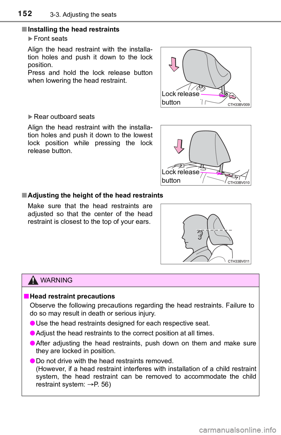
■Installing the head restraints
Front seats
Rear outboard seats
■ Adjusting the height o f the head restraints
Align the head restraint with the installa-
tion holes and push it down to the lock
position.
Press and hold the lock release button
when lowering the head restraint.
Align the head restraint with the installa-
tion holes and push it down to the lowest
lock position while pressing the lock
release button.
Make sure that the head restraints are
adjusted so that the center of the head
restraint is closest to the top of your ears.
WARNING
■
Head restraint precautions
Observe the following precautions regarding the head restraints. Failure to
do so may result in death or serious injury.
● Use the head restraints designed for each respective seat.
● Adjust the head restraints to the correct position at all times.
● After adjusting the head restraints, push down on them and make sure
they are locked in position.
● Do not drive with the head restraints removed.
(However, if a head restraint interferes with installation of a child restraint
system, the head restraint can be removed to accommodate the ch ild
restraint system: P. 56)
Lock release
button
Lock release
button
Page 155 of 540

1553-4. Adjusting the steering wheel and mirrors
3
Operation of each component
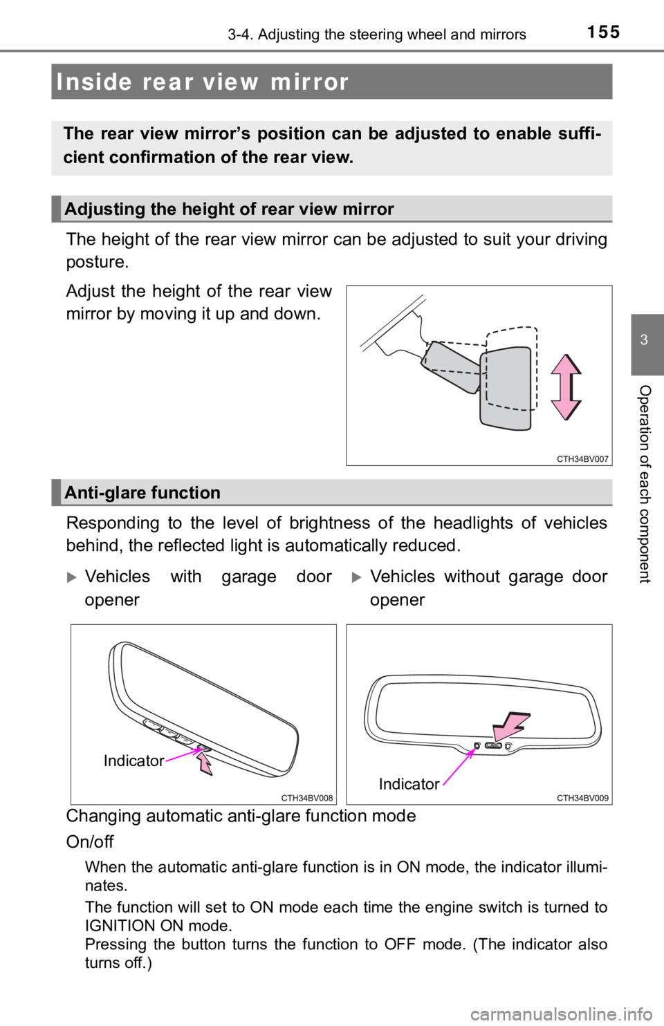
The height of the rear view mirror can be adjusted to suit your driving
posture.
Adjust the height of the rear view
mirror by moving it up and down.
Responding to the level of brightness of the headlights of vehi cles
behind, the reflected light is automatically reduced.
Changing automatic anti- glare function mode
On/off
When the automatic anti-glare function is in ON mode, the indic ator illumi-
nates.
The function will set to ON mode each time the engine switch is turned to
IGNITION ON mode.
Pressing the button turns the function to OFF mode. (The indica tor also
turns off.)
Inside rear view mirror
The rear view mirror’s position ca n be adjusted to enable suffi-
cient confirmation of the rear view.
Adjusting the height of rear view mirror
Anti-glare function
Vehicles with garage door
openerVehicles without garage door
opener
Indicator
Indicator