display TOYOTA AVALON 2022 Owners Manual
[x] Cancel search | Manufacturer: TOYOTA, Model Year: 2022, Model line: AVALON, Model: TOYOTA AVALON 2022Pages: 572, PDF Size: 9.42 MB
Page 2 of 572

TABLE OF CONTENTS2
For your information....................... 8
Reading this manual .................... 14
How to search .............................. 15
Pictorial index .............................. 16
1-1. For safe useBefore driving ...................... 26
For safe driving ................... 28
Seat belts ............................ 30
SRS airbags ........................ 36
Front passenger occupant classification system ......... 50
Safety information for children ............................. 55
Child restraint systems ........ 56
Installing child restraints ...... 60
Exhaust gas precautions ..... 70
1-2. Emergency assistance Safety Connect.................... 71
1-3. Theft deterrent system Engine immobilizer system............................... 77
Alarm ................................... 80 2. Instrument cluster
Warning lights and indicators ........................... 84
Gauges and meters ............. 90
Multi-information display ...... 93
Head-up display................. 111
Fuel consumption information....................... 118
1For safety and security
2Instrument cluster
Page 5 of 572
5
1
8 7 5 4
3
2
9
6
6-1. Maintenance and careCleaning and protecting the vehicle exterior .......... 386
Cleaning and protecting the vehicle interior ........... 389
6-2. Maintenance Maintenance requirements ................... 392
General maintenance ........ 394
Emission inspection and maintenance (I/M)
programs ......................... 398
6-3. Do-it-yourself maintenance
Do-it-yourself service precautions ..................... 399
Hood.................................. 401
Positioning a floor jack ...... 402
Engine compartment ......... 403
Tires .................................. 414
Tire inflation pressure........ 428
Wheels .............................. 431
Air conditioning filter .......... 433
Electronic key battery ........ 435
Checking and replacing fuses ............................... 438
Light bulbs ......................... 441 7-1. Essential information
Emergency flashers ........... 444
If your vehicle has to be stopped in
an emergency.................. 445
If the vehicle is submerged or water on the road is
rising ................................ 446
7-2. Steps to take in an emergency
If your vehicle needs to be towed ...................... 448
If you think something is wrong ........................... 453
Fuel pump shut off system ............................. 454
If a warning light turns on or a warning
buzzer sounds ................. 455
If a warning message is displayed...................... 465
If you have a flat tire .......... 470
If the engine will not start ................................. 482
If the electronic key does not operate properly ........ 484
If the vehicle battery is discharged ................... 487
If your vehicle overheats......................... 492
If the vehicle becomes stuck ................................ 495
6Maintenance and care7When trouble arises
Page 18 of 572
18Pictorial index
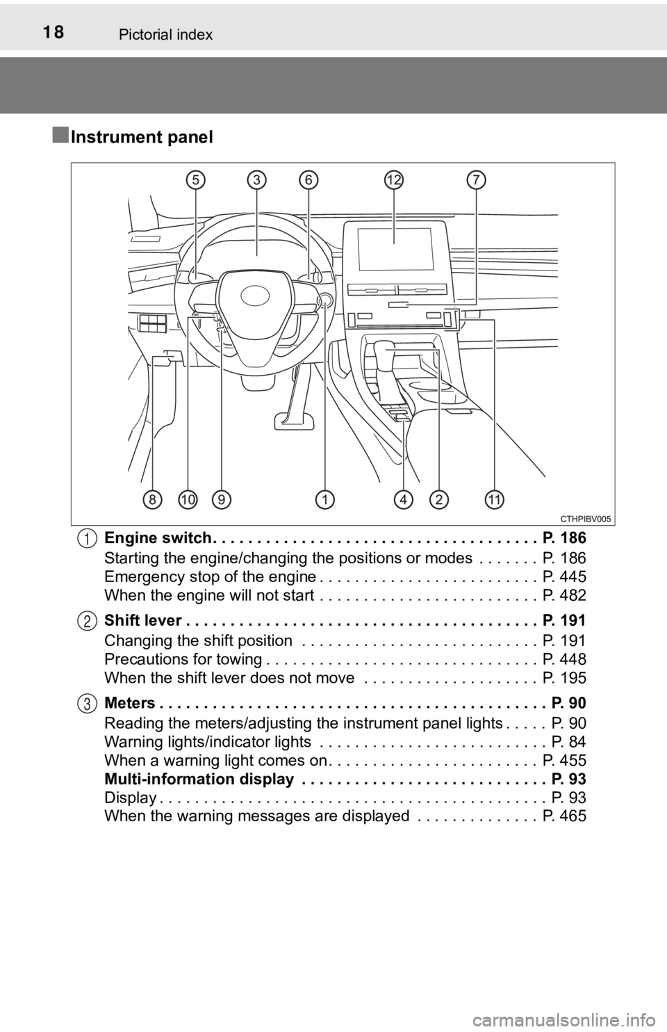
■Instrument panel
Engine switch . . . . . . . . . . . . . . . . . . . . . . . . . . . . . . . . . . . . . P. 186
Starting the engine/changing the positions or modes . . . . . . . P. 186
Emergency stop of the engine . . . . . . . . . . . . . . . . . . . . . . . . . P. 445
When the engine will not start . . . . . . . . . . . . . . . . . . . . . . . . . P. 482
Shift lever . . . . . . . . . . . . . . . . . . . . . . . . . . . . . . . . . . . . . . . . P. 191
Changing the shift position . . . . . . . . . . . . . . . . . . . . . . . . . . . P. 191
Precautions for towing . . . . . . . . . . . . . . . . . . . . . . . . . . . . . . . P. 448
When the shift lever does not move . . . . . . . . . . . . . . . . . . . . P. 195
Meters . . . . . . . . . . . . . . . . . . . . . . . . . . . . . . . . . . . . . . . . . . . . P. 90
Reading the meters/adjusting the instrument panel lights . . . . . P. 90
Warning lights/indicator lights . . . . . . . . . . . . . . . . . . . . . . . . . . P. 84
When a warning light comes on . . . . . . . . . . . . . . . . . . . . . . . . P. 455
Multi-information display . . . . . . . . . . . . . . . . . . . . . . . . . . . . P. 93
Display . . . . . . . . . . . . . . . . . . . . . . . . . . . . . . . . . . . . . . . . . . . . P. 93
When the warning messages are displayed . . . . . . . . . . . . . . P. 4651
2
3
Page 60 of 572
601-1. For safe use
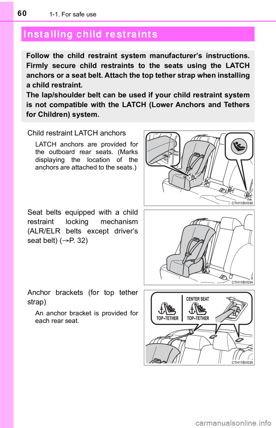
Child restraint LATCH anchors
LATCH anchors are provided for
the outboard rear seats. (Marks
displaying the location of the
anchors are attached to the seats.)
Seat belts equipped with a child
restraint locking mechanism
(ALR/ELR belts except driver’s
seat belt) (P. 32)
Anchor brackets (for top tether
strap)
An anchor bracket is provided for
each rear seat.
Installing child restraints
Follow the child restraint system manufacturer’s instructions.
Firmly secure child restraints to the seats using the LATCH
anchors or a seat belt. Attach t he top tether strap when installing
a child restraint.
The lap/shoulder belt can be used if your child restraint syste m
is not compatible with the LATCH (Lower Anchors and Tethers
for Children) system.
Page 83 of 572

83
Instrument cluster2
2. Instrument clusterWarning lights and indicators .......................... 84
Gauges and meters ............ 90
Multi-information display ..... 93
Head-up display ................ 111
Fuel consumption information ...................... 118
Page 86 of 572
862. Instrument cluster
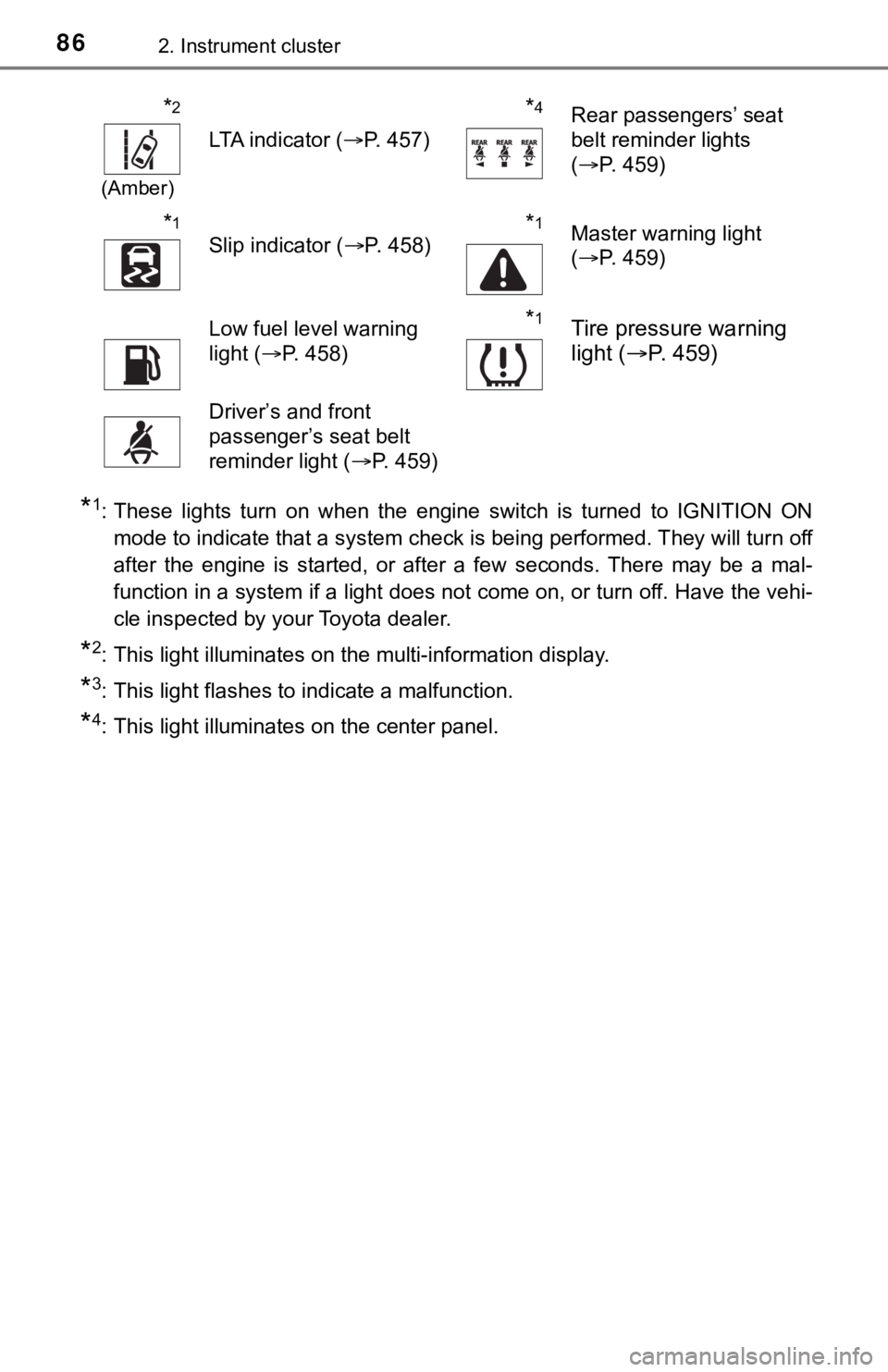
*1: These lights turn on when the engine switch is turned to IGNITION ON
mode to indicate that a system check is being performed. They will turn off
after the engine is started, or after a few seconds. There may be a mal-
function in a system if a light does not come on, or turn off. Have the vehi-
cle inspected by your Toyota dealer.
*2: This light illuminates on the multi-information display.
*3: This light flashes to indicate a malfunction.
*4: This light illuminates on the center panel.
*2
(Amber)
LTA indicator ( P. 457)
*4Rear passengers’ seat
belt reminder lights
(P. 459)
*1
Slip indicator ( P. 458)*1Master warning light
(P. 459)
Low fuel level warning
light ( P. 458)*1Tire pressure warning
light ( P. 459)
Driver’s and front
passenger’s seat belt
reminder light ( P. 459)
Page 89 of 572

892. Instrument cluster
2
Instrument cluster
*1: These lights turn on when the engine switch is turned to IGNITION ON
mode to indicate that a system check is being performed. They will turn off
after the engine is started, or after a few seconds. There may be a mal-
function in a system if a light does not come on, or turn off. Have the vehi-
cle inspected by your Toyota dealer.
*2: This light illuminates on the multi-information display.
*3: This light does not turn on when the system is disabled.
*4: This light turns on when the system is off.
*5: Depending on the operating condition, the color and illuminating/flashing state of the light change.
*6: This light flashes to indicate that the system is operating.
*7: These indicators will illuminate in the following situations to indicate thatthe system initial check is being performed:
• When the BSM function or RCTA function is enabled and the engi ne
switch is turned to IGNITION ON mode.
• When the engine switch is in IGNITION ON mode and the BSM function is enabled.
• When the engine switch is in IGNITION ON mode and the RCTA fun c-
tion is enabled. (At this time, a buzzer will also sound.)
The indicators will turn off after a few seconds. If the indicators do not
illuminate or turn off, or if a buzzer does not sound when the RCTA func-
tion is enabled, the system may be malfunctioning. Have the vehicle
inspected by your Toyota dealer.
*8: This light illuminates on the outside rear view mirrors.
*9: This light illuminates on the center panel.
*10: When the outside temperature is approximately 37°F (3°C) or lo wer, this
indicator will flash for approximately 10 seconds, then stay on .
WARNING
■If a safety system warning light does not come on
Should a safety system light such as the ABS and SRS warning lights not
come on when you start the engine, this could mean that these s ystems are
not available to help protect you in an accident, which could result in death
or serious injury. Have the vehicle inspected by your Toyota dealer immedi-
ately if this occurs.
Page 90 of 572
902. Instrument cluster
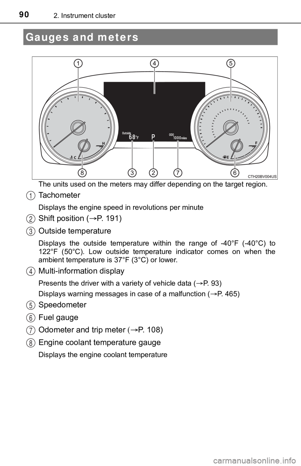
The units used on the meters may differ depending on the target region.
Tachometer
Displays the engine speed in revolutions per minute
Shift position (P. 1 9 1 )
Outside temperature
Displays the outside temperature within the range of -40°F (-40 °C) to
122°F (50°C). Low outside temperat ure indicator comes on when the
ambient temperature is 37°F (3°C) or lower.
Multi-information display
Presents the driver with a variety of vehicle data ( P. 93)
Displays warning messages in case of a malfunction ( P. 465)
Speedometer
Fuel gauge
Odometer and trip meter P. 1 0 8 )
Engine coolant temperature gauge
Displays the engine coolant temperature
Gauges and meters
1
2
3
4
5
6
7
8
Page 92 of 572
922. Instrument cluster
■The meters and display illuminate when
The engine switch is in IGNITION ON mode.
■ Brightness of the meters (day mode and night mode)
●The brightness of the meters is changed between day mode and ni ght
mode.
• Day mode: When the tail lights are off or when the tail lights are on but
the surrounding area is bright
• Night mode: When the tail lights are on and the surrounding area is dark
● When in night mode, the brightness will be reduced slightly unless the
meters are set to the maximum brightness level.
■ Outside temperature display
In the following situations, the correct outside temperature may not be dis-
played, or the display may take longer than normal to change:
●When stopped, or driving at low speeds (less than 16 mph [25 km/h])
● When the outside temperature has changed suddenly (at the entrance/exit
of a garage, tunnel, etc.)
● When “ ” or “E” is displayed, the system may be malfunctioning.
Take your vehicle to your Toyota dealer.
NOTICE
■To prevent damage to the engine and its components
● Do not let the indicator needle of the tachometer enter the red zone, which
indicates the maximum engine speed.
● The engine may be overheating if the engine coolant temperature gauge is
in the red zone (H). In this case, immediately stop the vehicle in a safe
place, and check the engine after it has cooled completely. ( P. 492)
Page 93 of 572
932. Instrument cluster
2
Instrument cluster
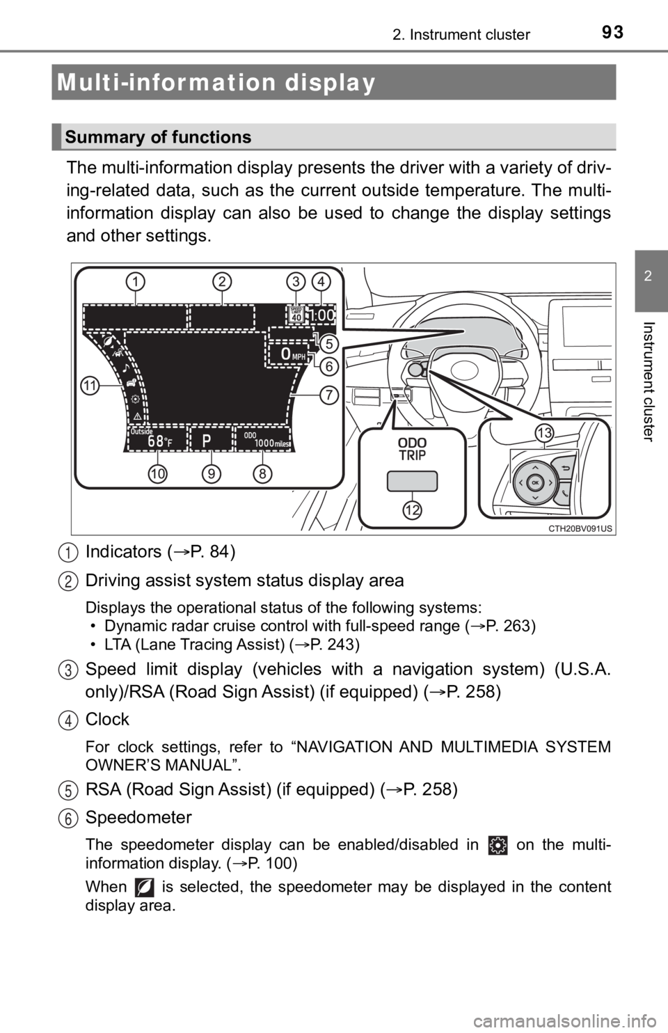
The multi-information display presents the driver with a variety of driv-
ing-related data, such as the cur rent outside temperature. The multi-
information display can also be used to change the display sett ings
and other settings.
Indicators ( P. 84)
Driving assist system status display area
Displays the operational status of the following systems:
• Dynamic radar cruise control with full-speed range ( P. 263)
• LTA (Lane Tracing Assist) ( P. 243)
Speed limit display (vehicles wit h a navigation system) (U.S.A.
only)/RSA (Road Sign Assist) (if equipped) ( P. 2 5 8 )
Clock
For clock settings, refer to “NAVIGATION AND MULTIMEDIA SYSTEM
OWNER’S MANUAL”.
RSA (Road Sign Assist) (if equipped) ( P. 258)
Speedometer
The speedometer display can be enabled/disabled in on the mult i-
information display. ( P. 100)
When is selected, the speedometer may be displayed in the content
display area.
Multi-infor mation display
Summary of functions
1
2
3
4
5
6