TOYOTA AVENSIS 2002 User Guide
AVENSIS 2002
TOYOTA
TOYOTA
https://www.carmanualsonline.info/img/14/57446/w960_57446-0.png
TOYOTA AVENSIS 2002 User Guide
Trending: warning light, steering, turn signal, low oil pressure, weight, transmission oil, reset
Page 11 of 1690
67±26
±
AUDI O & VISUAL SYSTE MANTENNA CORD SUB±ASSY NO.3
A VENSIS RE PAIR MANUAL (RM1018E)
24 . INS TALL ANTENNA CORD SUB±ASSY NO.3
(a ) Install the bolt.
T orque: 7.0 N �m (71 kgf �cm, 62 in. �lbf)
(b ) w/ Navigation:
Install the nut and scre w.
w/o Navigation:
Install the nut.
(c ) w/ Navigation:
Install the 11 clamps and the antenna cord sub±assy No.3.
w/o Navigation:
Install the 10 clamps and the antenna cord sub±assy No.3.
25 . INS TALL REAR SE ATBACK ASSY
( See page 40/60 FOLDING FLIP±UP CUSHION 72±21 , 40/60 FOLDING 72±27 )
26 . INS TALL FRONT SE AT ASSY RH ( See page POWER SE AT 72± 11 , MANUAL SE AT 72±16 )
Page 12 of 1690

AUDIO & VISUAL SYSTEM
PRECAUTION
1. OBSERVE HANDLING AND OPERATIONAL PRECAUTIONS
(a) Please explain to t")
670S4±01
± AUDIO & VISUAL SYSTEMAUDIO & VISUAL SYSTEM
67±1
AVENSIS REPAIR MANUAL (RM1018E)
AUDIO & VISUAL SYSTEM
PRECAUTION
1. OBSERVE HANDLING AND OPERATIONAL PRECAUTIONS
(a) Please explain to the customer that when the negative terminal is disconnected from the battery, the
channel information memory of the AM/FM broadcast stations in the radio receiver is cleared. If neces-
sary, make a note of the recorded channel information before the negative terminal is disconnected,
then reset the information after the negative terminal is reconnected.
(b) The removal/installation of the radio receiver should be performed after all the cassette tapes and au-
dio CDs are ejected from the radio receiver.
HINT:
If the cassette tapes and the audio CDs cannot be ejected due to the malfunction of the radio receiver, do
not try to drag them out by force. Bring the vehicle to the repair plant.
(c) Fasten the earth bolt securely when the antenna cord is removed or installed.
HINT:
Failing to fasten the earth bolt securely causes noise at the time of radio wave reception.
(d) Do not touch the cone paper of the speaker.
Page 13 of 1690
670S5±01
I35223
Instrument Cluster Finish Panel Garnish No.2
Radio Bracket No.2Radio Receiver Assy
Instrument Panel
Register Assy CTR
Air Conditioning Control AssyConsole Panel
Sub±assy Upper
Navigation System:Navigation Computer Cover
Instrument Panel
Support No.3 Instrument Panel
Support No.1Instrument Panel
Support No.2
Door Control Motor
Door Control Switch
Assy (TILT)
Instrument Cluster Finish Panel AssyDoor Control Switch Instrument Cluster Finish
Upper PanelMulti±display Instrument Panel Box
Door CoverRadio Bracket No.1
Instrument Panel
Register Control Gear
Control Knob
Protector No.1
Position Sensor
67±2
± AUDIO & VISUAL SYSTEMAUDIO & VISUAL SYSTEM
AVENSIS REPAIR MANUAL (RM1018E)
COMPONENTS
Page 14 of 1690
I35224
Front No.2 Speaker AssyAmplifier Antenna Assy
Front No.1 Speaker
Assy
Rear Speaker AssyNavigation System:
Disc Player Bracket No.2 Rivet
Navigation ECUPower Point Socket Cover
Power Point Socket Assy
Liftback:
Antenna Cord Sub±assy No.3Amplifier Antenna Assy Wagon:
Non±reusable part ��
Disc Player Bracket No.3
Rivet �
Rear No.2 Speaker Assy
Navigation ECU Cover
± AUDIO & VISUAL SYSTEMAUDIO & VISUAL SYSTEM
67±3
AVENSIS REPAIR MANUAL (RM1018E)
Page 15 of 1690
I35225
Navigation System:
Navigation Antenna Assy
Cigarette lighter Socket &
Retainer Assy
Cigarette lighter Knob
& Element Assy 67±4
± AUDIO & VISUAL SYSTEMAUDIO & VISUAL SYSTEM
AVENSIS REPAIR MANUAL (RM1018E)
Page 16 of 1690
670SJ±01
I35195
I35197Claw
I35196
I35205
±
AUDIO & VISUAL SYSTEM CIGARETTE LIGHTER ASSY
67±29
AVENSIS REPAIR MANUAL (RM1018E)
CIGARETTE LIGHTER ASSY
REPLACEMENT
1.REMOVE CONSOLE PANEL SUB±ASSY UPPER (See page 71±11)
2. REMOVE FRONT ASH RECEPTACLE ASSY
(a) Using a torx socket wrench (T20), remove the 4 screwsand front ash receptacle assy.
3. RE MO V E FRO NT AS H RE CE P TACLE RE TAINE R SUB±ASSY
(a) Disengage the claw and disconnect the connector.
(b) Push up the corner of the outer case open and remove the retainer assy as shown in the illustration.
4. REMOVE CIGARETTE LIGHTER ASSY
(a) Remove the 2 springs.
Page 17 of 1690
I351992 Claws
I35200
I35203
I35204
5.0mm
(0.20in.)
I35205
67±30
± AUDIO & VISUAL SYSTEMCIGARETTE LIGHTER ASSY
AVENSIS REPAIR MANUAL (RM1018E)
(b) Disengage the 2 claws and remove the door.
(c) Push out the cigarette lighter housing to the room side.
(d) Push out the cigarette lighter ring w/ wire harness to the
room side.
5. INSTALL CIGARETTE LIGHTER ASSY
(a) Align the claws of the cigarette lighter ring with the
notches of the cigarette lighter box to fix the cigarette
lighter w/ wire harness.
(b) Push the cigarette lighter housing to the out side.
(c) Install the wire harness as shown in the illustration.
(d) Place the wire harness in the position shown in the il-
lustration and install the door cover.
(e) Install the 2 springs.
Page 18 of 1690
I35206
I35195
± AUDIO & VISUAL SYSTEMCIGARETTE LIGHTER ASSY
67±31
AVENSIS REPAIR MANUAL (RM1018E)
(f) Make sure that the 2 springs are hooked on the claws and
install the retainer assy.
(g) Connect the connecter.
(h) Using a torx socket wrench (T20), install the 4 screws and
front ash receptacle.
Page 19 of 1690

(1)
(3)
H02440
Riveter
Mandrel
67±10
±
AUDIO & VISUAL SYSTEM FRONT NO.1 SPEAKER ASSY
AVENSIS REPAIR MANUAL (RM1018E)
FRONT NO.1 SPEAKER ASSY
REPLACEMENT
1.")
670S8±01
������I35168
������I35169
(2)
(1)
(3)
H02440
Riveter
Mandrel
67±10
±
AUDIO & VISUAL SYSTEM FRONT NO.1 SPEAKER ASSY
AVENSIS REPAIR MANUAL (RM1018E)
FRONT NO.1 SPEAKER ASSY
REPLACEMENT
1. REMOVE REAR DOOR WINDOW REGULATOR HANDLE ASSY (W/O POWER WINDOW) (See page 75±8)
2.REMOVE FRONT DOOR LOWER FRAME BRACKET GARNISH LH (See page 75±8)
3.REMOVE FRONT DOOR TRIM BASE LH (See page 75±8)
4.REMOVE FUEL LID OPENER SWITCH (See page 75±8)
5. REMOVE POWER WINDOW REGULATOR SWITCH ASSY (W/ POWER WINDOW) (See page 75±8)
6.REMOVE FRONT DOOR TRIM BOARD SUB±ASSY LH (See page 75±8)
7. REMOVE FRONT NO.1 SPEAKER ASSY
(a) Disconnect the connector.
(b) Using a drill of less then � 4 mm (0.16 in.), drill out the 3
rivet heads and remove the front No.1 speaker assy from
the front door panel.
(c) Gently and vertically put the drill to the rivet, and cut the rivet flanges.
NOTICE:
�Prizing the hole with a drill can lead to damage to the
rivet hole or breaking the drill.
�Take care as the cut rivet is hot.
(d) Even if flange is taken off, continue drilling and push out remaining fragments with the drill.
(e) Using a vacuum cleaner, remove the drilled rivet and their
dust from the inside of the front door panel.
8. INSTALL FRONT NO.1 SPEAKER ASSY
(a) Using an air riveter or a hand riveter, install 3 new strike rivets to install the front No.1 speaker assy on the front
door panel.
NOTICE:
�Install the new strike rivet in order shown in the il-
lustration to install the front No.1 speaker assy.
�Do not prize a riveter, as the riveter could be dam-
aged, loosened and the mandrel could be bent.
Page 20 of 1690
H02441
Riveter
Riveter
H02442
Riveter
± AUDIO & VISUAL SYSTEMFRONT NO.1 SPEAKER ASSY
67±11
AVENSIS REPAIR MANUAL (RM1018E)
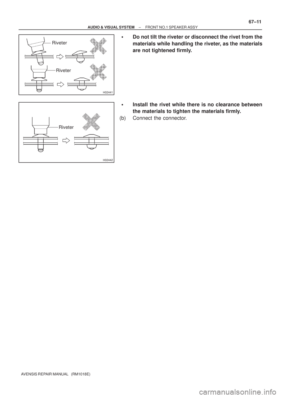
�Do not tilt the riveter or disconnect the rivet from the
materials while handling the riveter, as the materials
are not tightened firmly.
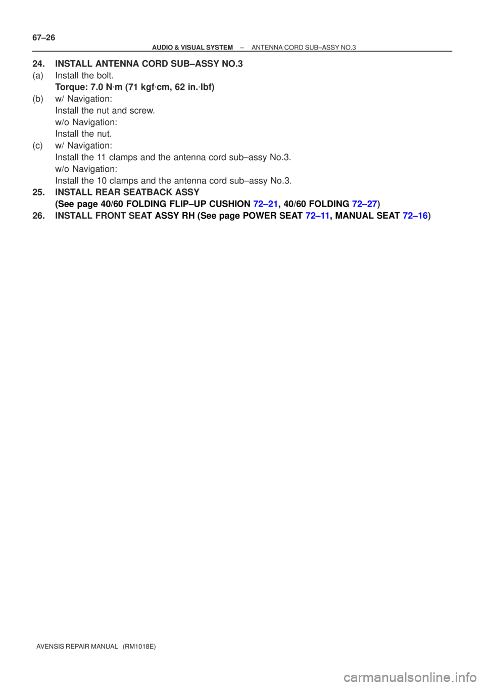
�Install the rivet while there is no clearance between
the materials to tighten the materials firmly.
(b) Connect the connector.
Trending: check transmission fluid, engine oil, brake rotor, auxiliary battery, Booster, transmission, engine coolant


CIGARETTE LIGHTER ASSY
REPLACEMENT
1.REMOVE CONSOLE PANEL SUB±ASSY U")

I35205
67±30
± AUDIO & VISUAL SYSTEMCIGARETTE LIGHTER ASSY
AVENSIS REPAIR MANUAL (RM1018E)
(b) Disengage the 2 claws and remove the door.
(c) Pu")

(f) Make sure that the 2 springs are hooked on the claws and
install the retainer assy.
(g) Connec")