stop start TOYOTA BZ4X 2022 Owners Manual (in English)
[x] Cancel search | Manufacturer: TOYOTA, Model Year: 2022, Model line: BZ4X, Model: TOYOTA BZ4X 2022Pages: 674, PDF Size: 120.02 MB
Page 7 of 674
5
Owners Manual_Europe_M42D76_en
TABLE OF CONTENTS
1
6
5
4
3
2
8
7
9
Maintenance requirements . 463
7-3. Do-it-yourself maintenance
Do-it-yourself service precau-
tions .................................. 465
Hood ................................... 467
Positioning a floor jack ........ 468
Motor compartment............. 470
Tires .................................... 476
Replacing the tire ................ 488
Tire inflation pressure ......... 494
Wheels ................................ 495
Air conditioning filter ........... 496
Electronic key battery ......... 499
Checking and replacing fuses
.......................................... 501
Light bulbs .......................... 504
8-1. Essential information
Emergency flashers ............ 506
If your vehicle has to be stopped
in an emergency ............... 506
If the vehicle is submerged or
water on the road is rising 507
8-2. Steps to take in an emergency
If your vehicle needs to be towed
.......................................... 509
If you think something is wrong
.......................................... 513
If a warning light turns on or a
warning buzzer sounds..... 515
If a warning message is dis-
played ............................... 523
If you have a flat tire ........... 528
If the EV system will not start
.......................................... 539
If you lose your keys ........... 541
If the charging port lids cannot
be opened......................... 541
If the electronic key does not
operate properly ............... 542
If the 12-volt battery is dis-
charged............................. 544
If your vehicle overheats ..... 549
If the vehicle becomes stuck
.......................................... 551
9-1. Specifications
Maintenance data ............... 554
9-2. Customization
Customizable features ........ 561
9-3. Initialization
Items to initialize ................. 574
What to do if... (Troubleshooting)
.......................................... 576
Alphabetical Index .............. 579
8When trouble arises
9Vehicle specifications
Index
Page 17 of 674
15
Owners Manual_Europe_M42D76_en
Pictorial index
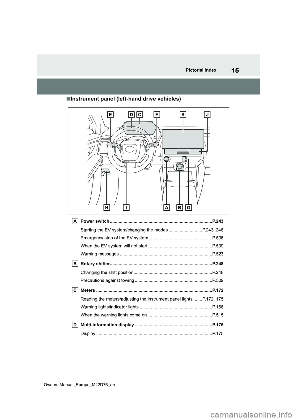
■Instrument panel (left-hand drive vehicles)
Power switch ..................................................................................P.243
Starting the EV system/changing the modes ...................... .....P.243, 246
Emergency stop of the EV system ................................ ...................P.506
When the EV system will not start .............................. .....................P.539
Warning messages ............................................... ...........................P.523
Rotary shifter................................................. .................................P.248
Changing the shift position.................................... ...........................P.248
Precautions against towing ..................................... .........................P.509
Meters ......................................................... ....................................P.172
Reading the meters/adjusting the instrument panel lights ....... P.172, 175
Warning lights/indicator lights ................................ ..........................P.168
When the warning lights come on ................................ ....................P.515
Multi-information display ...................................... ........................P.175
Display ........................................................ .....................................P.175
Page 25 of 674
23
Owners Manual_Europe_M42D76_en
Pictorial index
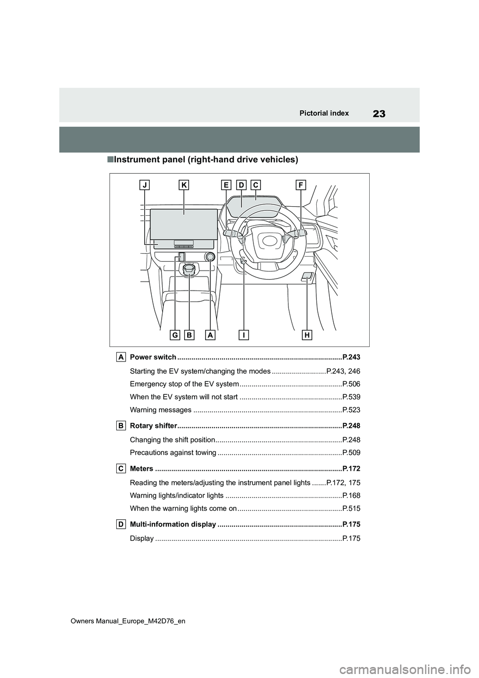
■Instrument panel (right-hand drive vehicles)
Power switch ..................................................................................P.243
Starting the EV system/changing the modes ...................... .....P.243, 246
Emergency stop of the EV system ................................ ...................P.506
When the EV system will not start .............................. .....................P.539
Warning messages ............................................... ...........................P.523
Rotary shifter................................................. .................................P.248
Changing the shift position.................................... ...........................P.248
Precautions against towing ..................................... .........................P.509
Meters ......................................................... ....................................P.172
Reading the meters/adjusting the instrument panel lights ....... P.172, 175
Warning lights/indicator lights ................................ ..........................P.168
When the warning lights come on ................................ ....................P.515
Multi-information display ...................................... ........................P.175
Display ........................................................ .....................................P.175
Page 34 of 674
32
Owners Manual_Europe_M42D76_en
1-1. For safe use
1-1.For s afe us e
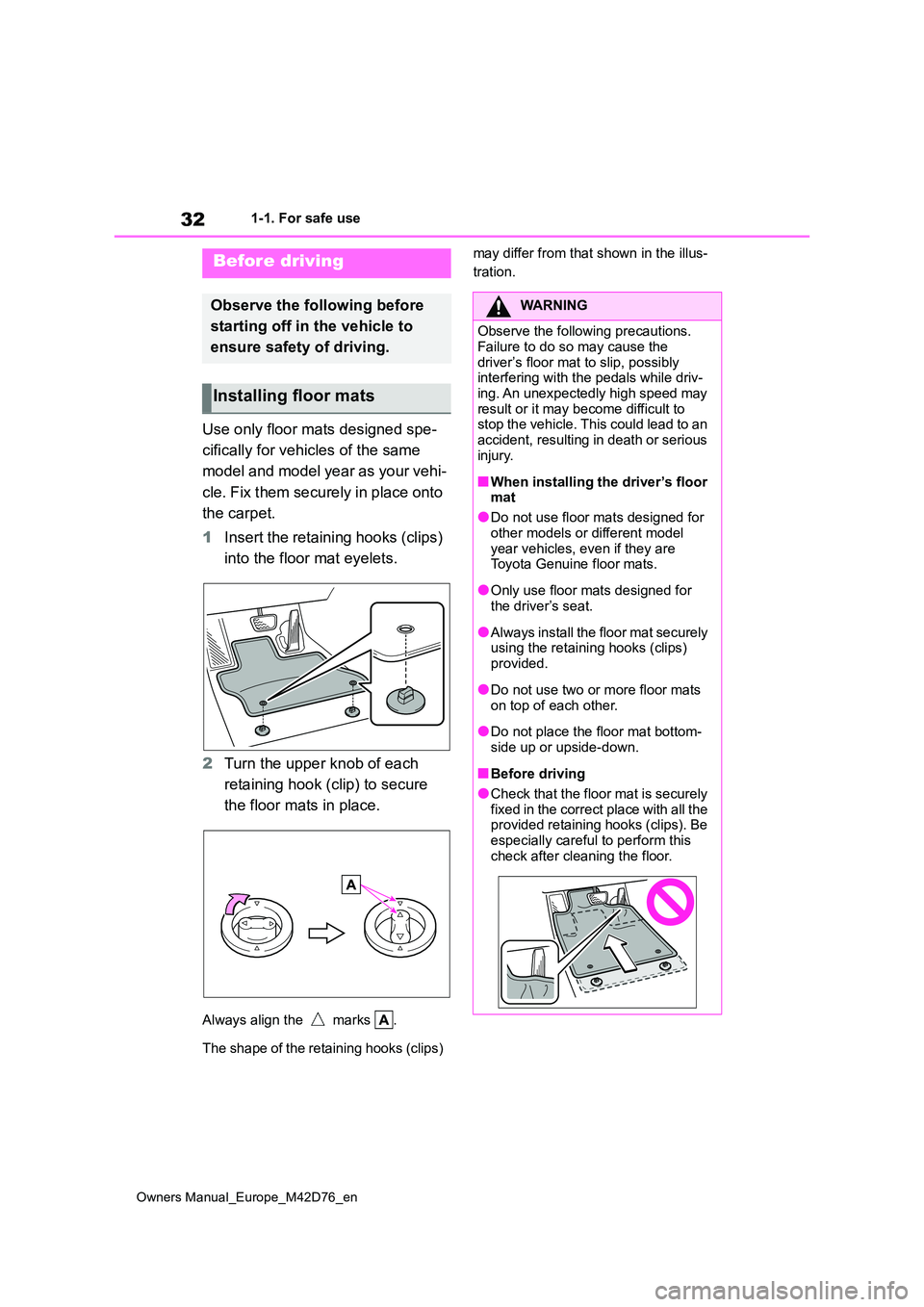
Use only floor mats designed spe-
cifically for vehicles of the same
model and model year as your vehi-
cle. Fix them securely in place onto
the carpet.
1 Insert the retaining hooks (clips)
into the floor mat eyelets.
2 Turn the upper knob of each
retaining hook (clip) to secure
the floor mats in place.
Always align the marks .
The shape of the retaining hooks (clips)
may differ from that shown in the illus-
tration.Before driving
Observe the following before
starting off in t he vehicle to
ensure safety of driving.
Installing floor mats
WARNING
Observe the following precautions.
Failure to do so may cause the driver’s floor mat to slip, possibly interfering with the pedals while driv-
ing. An unexpectedly high speed may result or it may become difficult to stop the vehicle. This could lead to an
accident, resulting in death or serious injury.
■When installing the driver’s floor mat
●Do not use floor mats designed for
other models or different model year vehicles, even if they are Toyota Genuine floor mats.
●Only use floor mats designed for the driver’s seat.
●Always install the floor mat securely using the retaining hooks (clips)
provided.
●Do not use two or more floor mats
on top of each other.
●Do not place the floor mat bottom-
side up or upside-down.
■Before driving
●Check that the floor mat is securely fixed in the correct place with all the provided retaining hooks (clips). Be
especially careful to perform this check after cleaning the floor.
Page 36 of 674
34
Owners Manual_Europe_M42D76_en
1-1. For safe use
Make sure that all occupants are
wearing their seat belts before driv-
ing the vehicle. ( P.36)
Use a child restraint system appro-
priate for the child until the child
becomes large enough to properly
wear the vehicle’s seat belt.
( P. 4 9 )
Make sure that you can see the
rear of the vehicle clearly, by
adjusting the inside rear view mirror
and outside rear view mirrors prop-
erly. ( P.216, 217)
WARNING
Observe the following precautions. Failure to do so may result in death or
serious injury.
●Do not adjust the position of the
driver’s seat while driving. Doing so could cause the driver to lose control of the vehicle.
●Do n ot p la ce a cu s hi on b et we en t he driver or passenger and the
seatback. A cushion may prevent correct pos-ture from being achieved, and
reduce the effectiveness of the seat belt and head restraint.
●Do not place anything under the front seats.Objects placed under the front
seats may become jammed in the seat tracks and stop the seat from locking in place. This may lead to
an accident and the adjustment mechanism may also be damaged.
●Always observe the legal speed limit when driving on public roads.
●When driving over long distances, take regular breaks before you start to feel tired. Also, if you feel tired or
sleepy while driving, do not force yourself to continue driving and take a break immediately.
Correct use of the seat belts
Adjusting the mirrors
Page 77 of 674
75
1
Owners Manual_Europe_M42D76_en
1-4. Theft deterrent system
For safety and security
1-4.Theft de terre nt sys te m
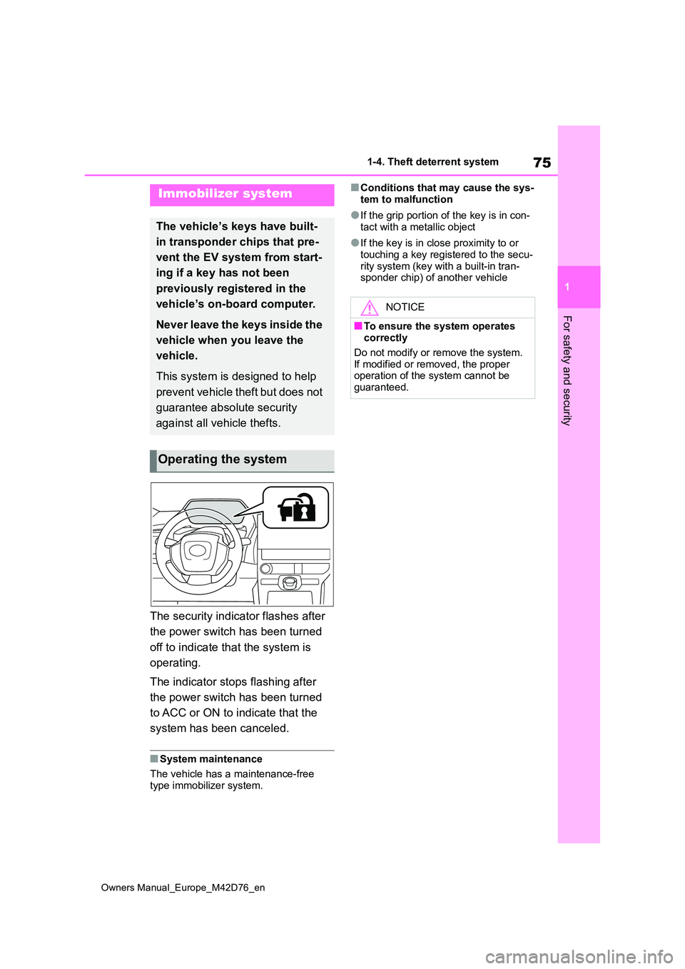
The security indicator flashes after
the power switch has been turned
off to indicate that the system is
operating.
The indicator stops flashing after
the power switch has been turned
to ACC or ON to indicate that the
system has been canceled.
■System maintenance
The vehicle has a maintenance-free type immobilizer system.
■Conditions that may cause the sys-
tem to malfunction
●If the grip portion of the key is in con-
tact with a metallic object
●If the key is in close proximity to or
touching a key registered to the secu- rity system (key with a built-in tran-sponder chip) of another vehicle
Immobilizer system
The vehicle’s keys have built-
in transponder chips that pre-
vent the EV system from start-
ing if a key has not been
previously registered in the
vehicle’s on-board computer.
Never leave the keys inside the
vehicle when you leave the
vehicle.
This system is designed to help
prevent vehicle theft but does not
guarantee absolute security
against all vehicle thefts.
Operating the system
NOTICE
■To ensure the system operates correctly
Do not modify or remove the system.
If modified or removed, the proper operation of the system cannot be guaranteed.
Page 79 of 674
77
1
Owners Manual_Europe_M42D76_en
1-4. Theft deterrent system
For safety and security
*: If equipped
■Items to check before locking
the vehicle
To prevent unexpected triggering of
the alarm and vehicle theft, make
sure of the following.
Nobody is in the vehicle.
The windows are closed before
the alarm is set.
No valuables or other personal
items are left in the vehicle.
■Setting
Close the doors and hood, and lock
all the doors using the entry func-
tion or wireless remote control. The
system will be set automatically
after 30 seconds.
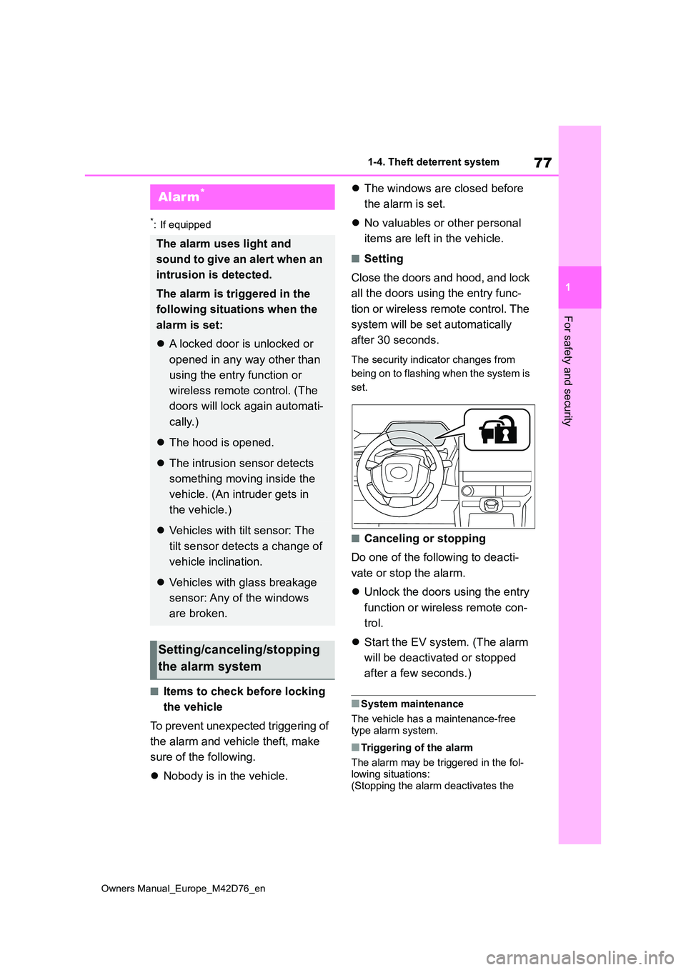
The security indicator changes from
being on to flashing when the system is
set.
■Canceling or stopping
Do one of the following to deacti-
vate or stop the alarm.
Unlock the doors using the entry
function or wireless remote con-
trol.
Start the EV system. (The alarm
will be deactivated or stopped
after a few seconds.)
■System maintenance
The vehicle has a maintenance-free type alarm system.
■Triggering of the alarm
The alarm may be triggered in the fol-
lowing situations: (Stopping the alarm deactivates the
Alarm*
The alarm uses light and
sound to give an alert when an
intrusion is detected.
The alarm is triggered in the
following situations when the
alarm is set:
A locked door is unlocked or
opened in any way other than
using the entry function or
wireless remote control. (The
doors will lock again automati-
cally.)
The hood is opened.
The intrusion sensor detects
something moving inside the
vehicle. (An intruder gets in
the vehicle.)
Vehicles with tilt sensor: The
tilt sensor detects a change of
vehicle inclination.
Vehicles with glass breakage
sensor: Any of the windows
are broken.
Setting/canceling/stopping
the alarm system
Page 86 of 674
84
Owners Manual_Europe_M42D76_en
2-1. Electric vehicle system
■Charging the traction battery
Be sure to maintain the traction battery charge level suitable for your driving needs.
If the traction battery fully discharges, the vehicle cannot be driven at all. When the battery becomes low, charge it as
soon as possible.
■If the traction battery becomes low
●If the traction battery becomes low,
the traction battery charge warning light comes on or flashes and a mes-sage will be displayed on the multi-
information display. ( P.517)
●If the traction battery is completely
discharged, the EV system cannot be started and driving will not be possi-ble. When the traction battery
becomes low, charge it as soon as possible.
■Sounds and vibrations specific to an battery electric vehicle
Because there is no engine sound or vibration, it is easy to mistake the bat-tery electric vehicle for being off when it
is actually still running, as indicated by the “READY” indicator being illuminated. For safety, make sure to always shift the
shift position to P and apply the parking brake when parked.
Before and after the EV system is
started, the following sounds and vibra- tions may occur. However, these sounds and/or vibrations are not signs of mal-
functions:
●The brake system operation sound
may be heard from the front of the vehicle when the driver’s door is opened.
●Motor sounds may be heard from the motor compartment or luggage com-
partment.
●Electrical relay sounds may be heard
from the motor compartment when the EV system starts or stops.
●Relay operating sounds such as a snap or soft clank will be emitted from the traction battery in the following sit-
uations:
• When the EV system is started or stopped• When charging starts or completes
• When the vehicle is driven the first time after the traction battery has been charged using DC charging
●Sounds may be heard due to regener-ative braking when the brake pedal is
depressed or as the accelerator pedal is released.
●Cooling fan operating sounds from the radiator.
●The operation sound of the air condi-tioning system (air conditioning com-pressor, blower motor).
■Maintenance, repair, recycling, and
disposal
Contact any authorized Toyota retailer or Toyota authorized repairer, or any reli-
able repairer regarding maintenance, repair, recycling and disposal. Do not dispose of the vehicle yourself.
A sound which changes in accor-
dance with the driving speed, will
be played in order to warn people
nearby of the vehicle’s approach.
This sound may be heard inside the
vehicle. The sound will stop when
the vehicle speed exceeds approxi-
mately 25 km/h (15 mph).
■Acoustic Vehicle Alerting System
In the following cases, the Acoustic Vehicle Alerting System may be difficult
for surrounding people to hear.
●In very noisy areas
●In the wind or the rain
Also, as the Acoustic Vehicle Alerting
System is installed on the front of the
Acoustic Vehicle Alerting
System
Page 92 of 674
90
Owners Manual_Europe_M42D76_en
2-1. Electric vehicle system
When a certain level of impact is
detected by the impact sensors, the
emergency shut off system turns off
the EV system and blocks the high
voltage current. If the emergency
shut off system activates, your vehi-
cle will not restart. To restart the EV
system, contact any authorized
Toyota retailer or Toyota authorized
repairer, or any reliable repairer.
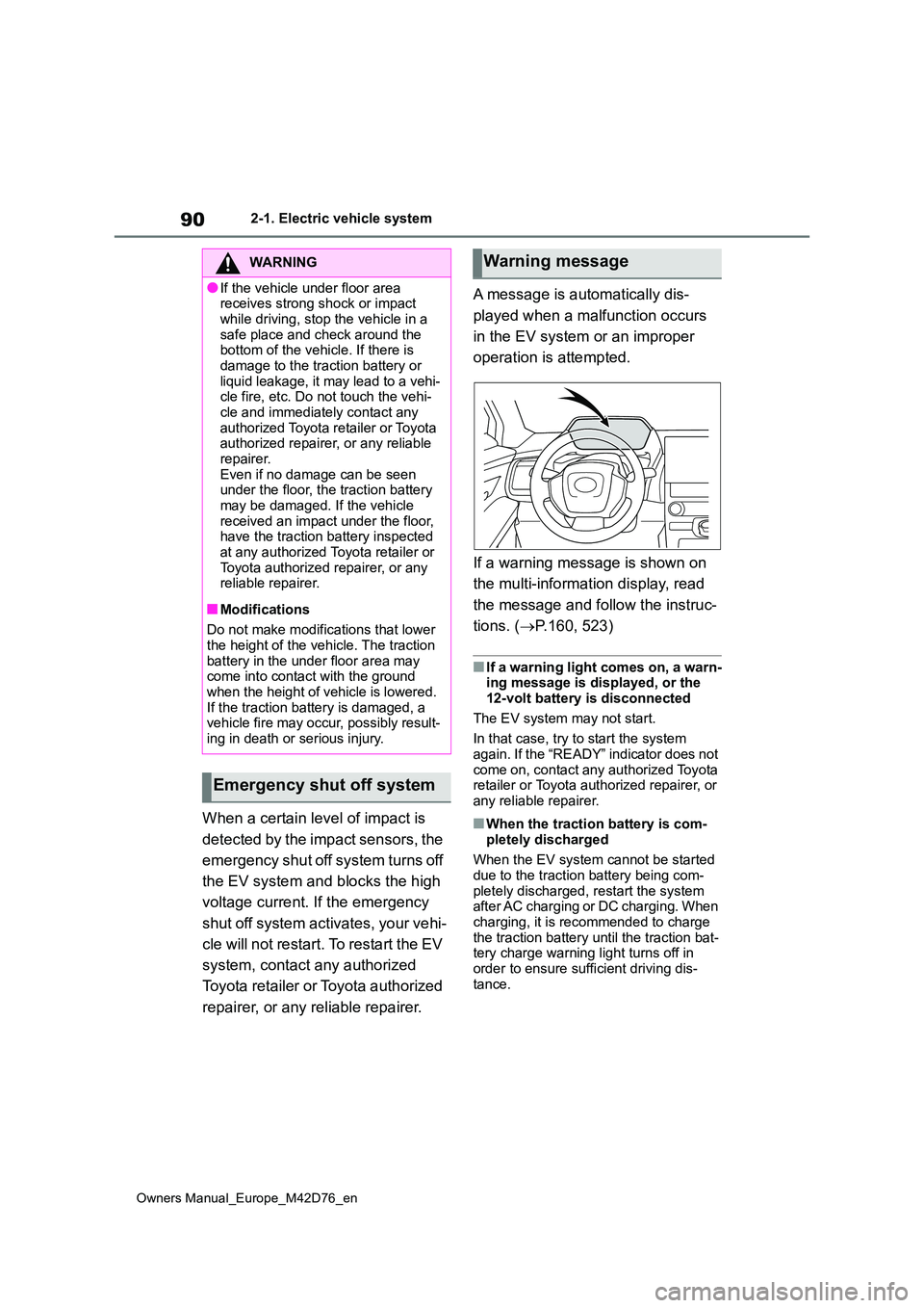
A message is automatically dis-
played when a malfunction occurs
in the EV system or an improper
operation is attempted.
If a warning message is shown on
the multi-information display, read
the message and follow the instruc-
tions. ( P.160, 523)
■If a warning light comes on, a warn- ing message is displayed, or the 12-volt battery is disconnected
The EV system may not start.
In that case, try to start the system again. If the “READY” indicator does not
come on, contact any authorized Toyota retailer or Toyota authorized repairer, or any reliable repairer.
■When the traction battery is com-
pletely discharged
When the EV system cannot be started due to the traction battery being com-
pletely discharged, restart the system after AC charging or DC charging. When
charging, it is recommended to charge the traction battery until the traction bat-tery charge warning light turns off in
order to ensure sufficient driving dis- tance.
WARNING
●If the vehicle under floor area receives strong shock or impact
while driving, stop the vehicle in a safe place and check around the bottom of the vehicle. If there is
damage to the traction battery or liquid leakage, it may lead to a vehi-cle fire, etc. Do not touch the vehi-
cle and immediately contact any authorized Toyota retailer or Toyota authorized repairer, or any reliable
repairer. Even if no damage can be seen under the floor, the traction battery
may be damaged. If the vehicle received an impact under the floor, have the traction battery inspected
at any authorized Toyota retailer or Toyota authorized repairer, or any reliable repairer.
■Modifications
Do not make modifications that lower
the height of the vehicle. The traction battery in the under floor area may come into contact with the ground
when the height of vehicle is lowered. If the traction battery is damaged, a vehicle fire may occur, possibly result-
ing in death or serious injury.
Emergency shut off system
Warning message
Page 112 of 674
110
Owners Manual_Europe_M42D76_en
2-2. Charging
■Locking the charging connec-
tor
The AC charging connector will be
automatically locked when inserting
it into the AC charging inlet.
■Unlocking the charging con-
nector
The AC charging connector will be
unlocked when the doors are
unlocked using the smart entry &
start system or wireless remote
control.
The AC charging connector locks
when connected and unlocks when
the door is unlocked, so lock-
ing/unlocking the AC charging con-
nector does not necessarily
correspond to locking/unlocking the
door.
If the door is unlocked and the AC
charging connector is locked, you
can unlock it by doing the following:
• When using the smart entry &
start system, lock the door once
and then unlock it again.
(→P.185)
• When using the wireless remote
control, press the unlock button
to unlock the door. (→P.185)
■AC charging connector lock func-
tion
If the AC charging connector is locked/unlocked repeatedly, it may not
work temporary due to protect the sys- tem by AC charging system. In this case, wait for a while before connecting
the AC charging connector to AC charging inlet again.
The AC charging connector lock func-
tion does not guarantee that theft of the AC charging cable will be prevented, and is not necessarily effective for all
mischiefs.
■Security function for unlocking
If the AC charging connector is not removed within approximately 30 sec-
onds after the vehicle is unlocked, the security function automatically locks the connector again.
■Unlocking the AC charging connec-
tor during charging
If the AC charging connector is unlocked during charging, charging will be
stopped. Once the security function ( P.77) works, charging may not restart automatically. In this case, remove the
AC charging connector* and insert it again.*: When the AC charging connector is
removed, the charging schedule will
be updated. ( P.134)
■When the AC charging connector cannot be inserted into the AC
charging inlet
Check that the connector lock pin is not lowered.
If the connector lock pin is lowered, the connector lock is operating. Unlock the doors using the smart entry & start sys-
Locking and unlocking
AC charging connector
The AC charging connector
will be locked when it is con-
nected to the AC charging
inlet, preventing the AC
charging cable from being dis-
connected while charging.
Locking and unlocking the
AC charging connector