Multimedia system TOYOTA BZ4X 2023 Owners Manual
[x] Cancel search | Manufacturer: TOYOTA, Model Year: 2023, Model line: BZ4X, Model: TOYOTA BZ4X 2023Pages: 628, PDF Size: 11.91 MB
Page 18 of 628
18Pictorial index
Owners Manual_USA_M42C01_en
Turn signal lever.............................................. ................... P.242
Headlight switch ............................................... ................. P.248
Headlights/parking lights/tail lig hts/license plate lights/daytime run-
ning lights .................................................... ......................... P.248
Windshield wiper and washer switch............................... P.253
Usage................................................................................... P.253
Adding washer fluid .............................................................. P.471
Warning messages ............................................... ............... P.522
Emergency flasher switch ....................................... .......... P.504
Hood lock release lever ........................................ ............. P.462
Tilt and telescopic steering lock release lever ................P. 1 9 9
Adjustment ..................................................... ...................... P.199
Air conditioning system ............................. ....................... P.402
Usage................................................................................... P.402
Rear window defogger ........................................... .............. P.404
Multimedia system
*
*
: Refer to “MULTIMEDIA OWNER’S MANUAL”.
Page 94 of 628
942-2. Charging
Owners Manual_USA_M42C01_en
3Press or of the meter
control switches to select
“Charging Settings”, and then
press .
The “Charging Settings” screen will
be displayed.
4Press or of the meter
control switches to select
“Connector Lock”, and then
press .
The “Connector L ock” screen will
be displayed.
Multimedia operation
1 Select on the main menu.
2 Select “Vehicle customize”.
3 Select “Charging”.
4 Select “Connector lock”.
AC charging connector lock-
ing/unlocking settings can be
changed as follows.
*1: The AC charging connector will be unlocked if power supply is
interrupted due to a power out-
age, etc., after the AC charging
connector is automatically
locked.
*2: The AC charging connector can be unlocked by similar opera-
tions to that of “Auto Lock”
(Default setting).
*3: When the stop time of the charging schedule “Start-Stop”
setting is reached, the AC
charging connector is unlocked
even if it is not fully charged.
SettingOperation
description
“Auto Lock”
(Default setting)
The AC charging
connector is
automatically
locked when the
AC charging
connector is con-
nected.
“Auto Lock & Unlock”
The AC charging
connector is
automatically
locked when the
AC charging
connector is con-
nected and auto-
matically
unlocked when
charging is com-
pleted.
*1, 2, 3
“OFF”
Not using the AC
charging con-
nector locking
system
Page 109 of 628
1092-2. Charging
Owners Manual_USA_M42C01_en
2
Electric Vehicle system
1 Press or of the meter
control switches to select .
2 Press or of the meter
control switches to select “Vehi-
cle Settings”, and then press and
hold .
3 Press or of the meter
control switches to select
“Charging Settings”, and then
press .
The “Charging Sett ings” screen will
be displayed.
4 Press or of the meter
control switches to select
“Charging Limit”, and then press
.
The “Charging Limit” screen will be
displayed.
5 Select “Full”, “90%”, “80%”,
“70%”, “60%” or “50%” and then
press .
●Setting operations on multimedia
1 Select .
2 Select “Vehicle customize”.
3 Select “Charging”.
4 Select “Charging limit”.
5 Select “Full”, “90%”, “80%”,
“70%”, “60%” or “50%”.
If the setting is changed during DC
charging, charging may stop due to
the operation of the DC charger
timer and the traction battery cannot
be fully charged.
■Protection function of AC
charging inlet overheating
By installing a temp erature sensor
to the AC charging inlet, prevents
parts from melting when the tem-
perature rises due to foreign matter
entering the charging connector. When a certain temperature
increase is detected, charging is
stopped immediately.
After this, when the power switch is
off, a message will be displayed on
the multi-information display
(
P.140)
WARNING
■When charging
Observe the following precau-
tions.
Failure to do so may cause an
unexpected accident, resulting in
death or serious injury.
●Connect to a power source suit-
able for charging. ( P. 9 6 )
●Check that the AC charging
cable, plug and outlet are free of
foreign matter.
●Before charging, check that the
AC charging inlet is not
deformed, damaged or cor-
roded, and check that the inlet
is free of foreign matter such as
dirt, snow and ice.
If there is dirt or dust in these
areas, remove completely
before inserting the charging
connector.
●Do not get the te rminals of the
AC charging inlet wet.
●Only use outlets where the plug
can be securely inserted.
●Do not bundle or wind the AC
charging cable while charging,
as doing so may result in over-
heating.
●Do not touch the terminals of
the charging connector and AC
charging inlet with a sharp metal
objects (needles, etc.,) or
hands, or short them with for-
eign objects.
Page 115 of 628
1152-2. Charging
Owners Manual_USA_M42C01_en
2
Electric Vehicle system
cannot be hear d due to noise
occurrence during DC charging
●As the battery approaches full
charge, the charging speed will
decrease and it will take longer to
complete charging.
●The time to complete charging
may change, or charging may
stop before reaching the upper
limit of the charge capacity, due to
the remaining charge of the trac-
tion battery, the outside tempera-
ture, the specifications of the
charger (stand), etc.
●It is recommended to avoid fre-
quent DC charging to prevent a
decline in the traction battery
capacity.
●Quickly move from the DC
charging space for other users
after the DC charging is com-
pleted.
■How to set the DC charging
power
You can change the DC charging
power limit on the multi-information
display or multimedia.
●Setting operations on multi-infor-
mation display
1 Press or of the meter
control switches to select .
2 Press or of the meter
control switches to select “Vehi-
cle Settings”, and then press and
hold .
3 Press or of the meter
control switches to select
“Charging Settings”, and then
press .
The “Charging Sett ings” screen will
be displayed.
4 Press or of the meter
control switches to select “DC charging power”, and then press
.
The “DC charging power” screen
will be displayed.
5 Press or of the meter
control switches to select the
charging power from “MAX”,
“125kW”, “100kW”, “75kW”,
“50kW” and then press .
*The maximum power when
charging is limited to the selected
power or less.
If “MAX” is selected , the vehicle will
be charged with the maximum
power that can be charged.
●Setting operations on multimedia
1 Select .
2 Select “Vehicle customize”.
3 Select “Charging”.
4 Select “DC charging power”.
5 Select from “MAX”, “125kW”,
“100kW”, “75kW”, “50kW”.
*The maximum power when
charging is limited to the selected
power or less.
If “MAX” is selected , the vehicle will
be charged with the maximum
power that can be charged.
■Changing the “Cha rging Limit”
settings
P.108
■If “Check Charging System
Close Charging Port Lid See
Owner’s Manual” is displayed
on the multi-information display
If the system check after DC
charging is not completed success-
fully, the EV system will not start
even if the power switch is pressed
while depressing the brake pedal.
Perform a system check with the fol-
lowing procedures.
Page 119 of 628
1192-2. Charging
Owners Manual_USA_M42C01_en
2
Electric Vehicle system
according to the set start time
and stop time.
*
*: There might be a slight error in the timing when charging starts
due to the state of the traction
battery.
■Repeated setting
The periodic charging schedule
can be set by selecting your
desired day of the week. Select
one or more day of the week to
do the charging schedule.
■Turning “Charge Now” on
and off
To start charging without chang-
ing the charging schedule set-
ting, turn “Charge Now” on to
temporarily cancel the charging
schedule and enable charging
after connecting the AC
charging connector.
*
*: If the charging connector is removed during charging while
the charging schedule is regis-
tered and “Charge Now” is on,
“Charge Now” turns off.
■“Next Event”
Of the registered charging
schedules, the closest charging
schedule after the current time
is called the “Next Event”.
For charging schedule, AC
charging will be performed
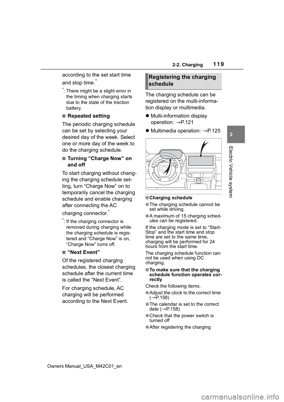
according to the Next Event. The charging schedule can be
registered on the multi-informa-
tion display or multimedia.
Multi-information display
operation: P.121
Multimedia operation: P. 1 2 5
■Charging schedule
●The charging schedule cannot be
set while driving.
●A maximum of 15 charging sched-
ules can be registered.
If the charging mode is set to “Start-
Stop” and the start time and stop
time are set to the same time,
charging will be performed for 24
hours from the start time.
The charging schedule function can
not be used when using DC
charging.
■To make sure that the charging
schedule function operates cor-
rectly
Check the following items.
●Adjust the clock to the correct time
( P.158)
●The calendar is set to the correct
date ( P.158)
●Check that the power switch is
turned off
●After registering the charging
Registering the charging
schedule
Page 125 of 628
1252-2. Charging
Owners Manual_USA_M42C01_en
2
Electric Vehicle systemFor details on how to operate
the audio system screen, refer
to “MULTIMEDIA OWNER’S
MANUAL”.
Setting operations related to the
charging schedule are per-
formed on the “Charging sched-
ule” screen.
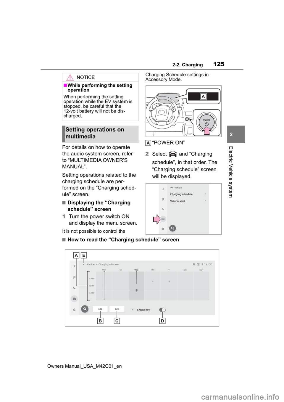
■Displaying the “Charging
schedule” screen
1 Turn the power switch ON
and display the menu screen.
It is not possible to control the Charging Schedule settings in
Accessory Mode.
“POWER ON”
2 Select and “Charging
schedule”, in that order. The
“Charging schedule” screen
will be displayed.
■How to read the “Charging schedule” screen
NOTICE
■While performing the setting
operation
When performing the setting
operation while t he EV system is
stopped, be careful that the
12-volt battery will not be dis-
charged.
Setting operations on
multimedia
Page 156 of 628
1563-1. Instrument cluster
Owners Manual_USA_M42C01_en
■Menu icons
The menu icons will be dis-
played by pressing the or
meter control switch.
■Liquid crystal display
Small spots or light spots may
appear on the display. This phenom-
enon is characteristi c of liquid crys-
tal displays, and there is no problem
continuing to use the display.
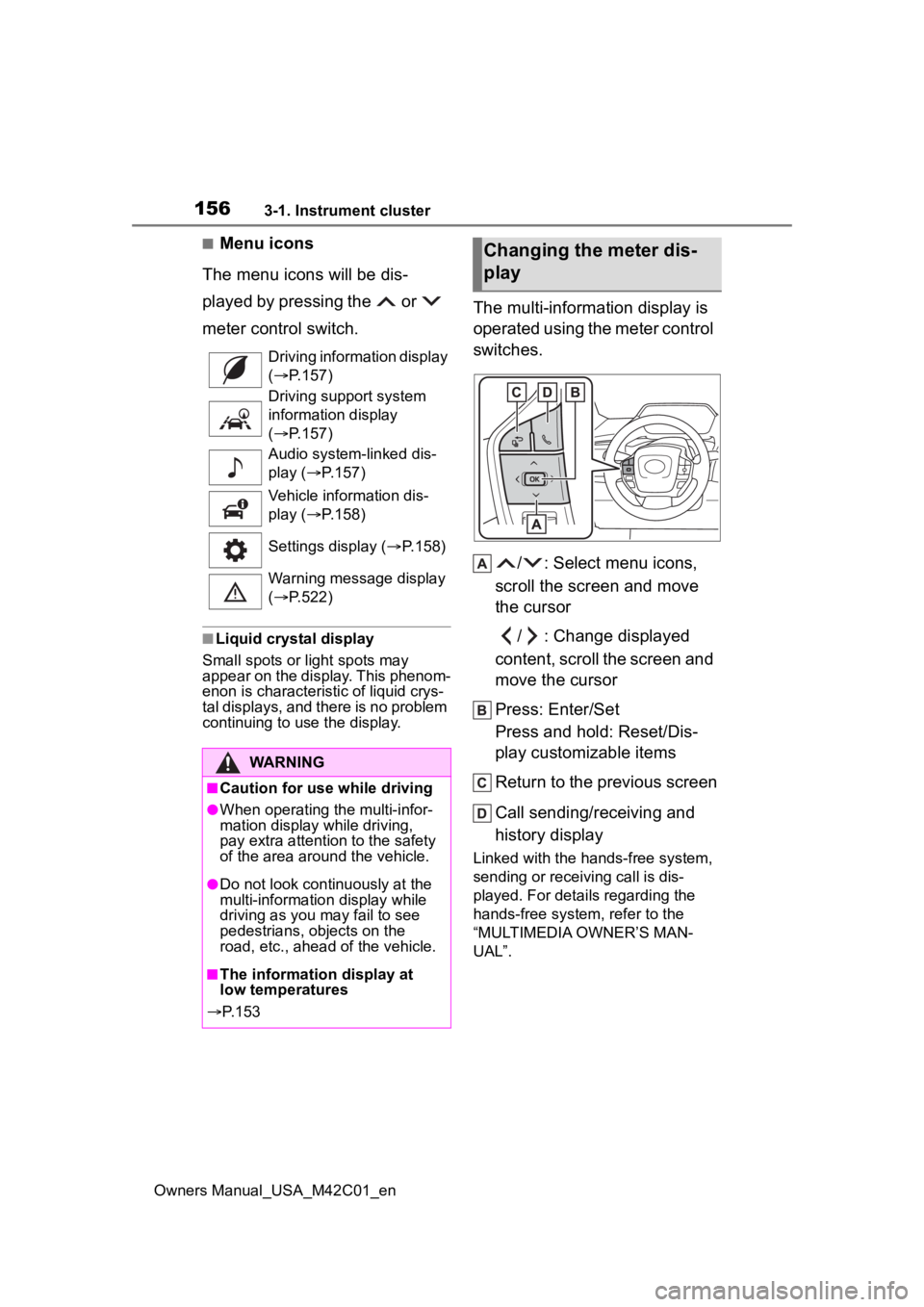
The multi-information display is
operated using the meter control
switches.
/ : Select menu icons,
scroll the screen and move
the cursor
/ : Change displayed
content, scroll the screen and
move the cursor
Press: Enter/Set
Press and hold: Reset/Dis-
play customizable items
Return to the previous screen
Call sending/receiving and
history display
Linked with the hands-free system,
sending or receiving call is dis-
played. For details regarding the
hands-free system, refer to the
“MULTIMEDIA OWNER’S MAN-
UAL”.
Driving information display
(
P.157)
Driving support system
information display
( P.157)
Audio system-linked dis-
play ( P.157)
Vehicle information dis-
play ( P.158)
Settings display ( P.158)
Warning message display
( P.522)
WARNING
■Caution for use while driving
●When operating the multi-infor-
mation display while driving,
pay extra attention to the safety
of the area aroun d the vehicle.
●Do not look continuously at the
multi-information display while
driving as you may fail to see
pedestrians, objects on the
road, etc., ahead of the vehicle.
■The information display at
low temperatures
P. 1 5 3
Changing the meter dis-
play
Page 215 of 628
2154-6. Favorite settings
Owners Manual_USA_M42C01_en
4
Before driving
4-6.Favorite settings
*: If equipped
An individual can be identified
using the following authentica-
tion devices.
Electronic key
An individual is identified when the
Smart key system detects their
electronic key.
Bluetooth devices
An individual can be detected if the
same Bluetooth d evice that was
used as a handsfree phone the last time the vehicle was entered is con-
nected to the audio system.
When an individual is identified
from an authentication device,
settings for the following func-
tions are recalled.
Meter displays and multime-
dia information
*
When an individual is identified, the
vehicle settings used when the
p o w e r s w i t c h w a s l a s t t u r n e d o ff a r e
recalled.
Vehicle settings that can be
set using the multimedia dis-
play
*
When an individual is identified, the
vehicle settings used when the
p o w e r s w i t c h w a s l a s t t u r n e d o ff a r e
recalled.
Safe driving support function*
When an individual is identified, the
vehicle settings used when the
p o w e r s w i t c h w a s l a s t t u r n e d o ff a r e
recalled.
*: Some settings are excluded
My Settings*
By recognizing an individ-
ual through a device, such
as an electronic key, and
vehicle settings recorded
for that driver can be
recalled when the vehicle is
entered. By assigning an
authentication device to a
driver in advance, the driver
can enter the vehicle with
their preferred settings. Set-
tings for up to 3 drivers can
be recorded by My Set-
tings. For details on how to
assign/delete electronic
keys, set driver names, per-
form initialization, change
drivers manually, or delete a
driver, refer to the “MULTI-
MEDIA OWNER’S MAN-
UAL”.
Types of assigned
authentication devices
Recalled functions
Page 311 of 628
3115-4. Using the driving support systems
Owners Manual_USA_M42C01_en
5
Driving
due to a strong impact to the sen-
sor or its surrounding area
• When a vehicle or bicycle
approaches from behind your
vehicle at an angle
• When the vehicle is stopped at an
angle to the road
• When a vehicle or bicycle approaches from behind a parked
vehicle at an angle
• When a parked vehicle, wall, sign, person or other stationary object
is behind the vehicle
• When an approaching vehicle or bicycle suddenly changes direc-
tion
• When an approaching vehicle or bicycle is traveling along a station-
ary object, such a wall or sign
• When the back door is open
• When a bicycle carrier, ramp, or other accessory is installed to the
back of the vehicle
• When a vehicle or bicycle is
approaching at high speed
• When towing with the vehicle
• When stopped on a steep incline
• When stopped on a curve or at the exit of a curve
*: If equipped
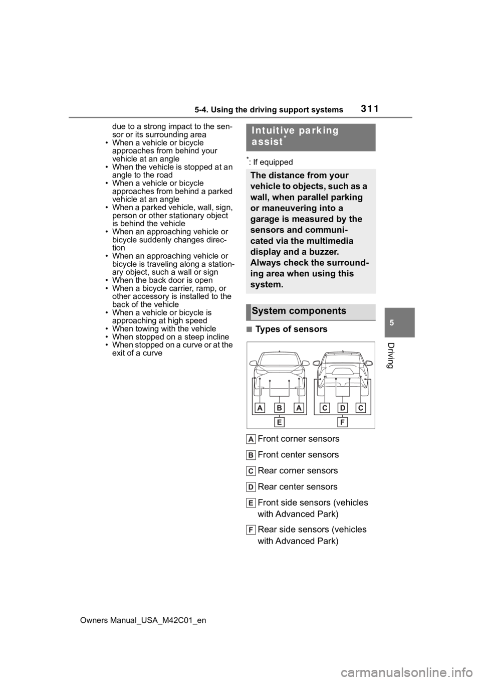
■Types of sensors
Front corner sensors
Front center sensors
Rear corner sensors
Rear center sensors
Front side sensors (vehicles
with Advanced Park)
Rear side sensors (vehicles
with Advanced Park)
Intuitive parking
assist*
The distance from your
vehicle to objects, such as a
wall, when parallel parking
or maneuvering into a
garage is measured by the
sensors and communi-
cated via the multimedia
display and a buzzer.
Always check the surround-
ing area when using this
system.
System components
Page 312 of 628
3125-4. Using the driving support systems
Owners Manual_USA_M42C01_en
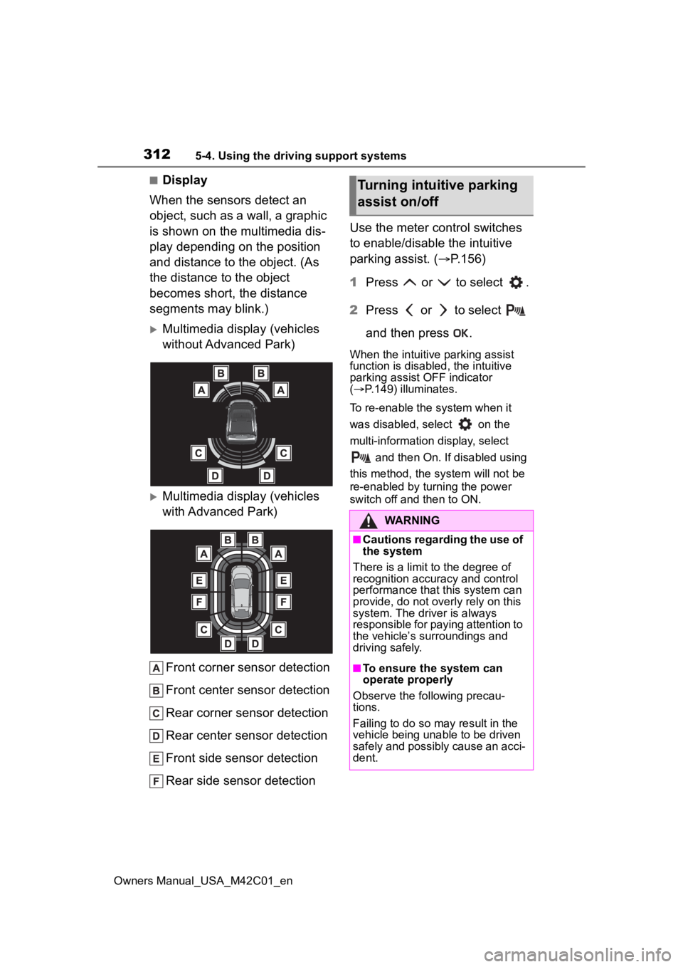
■Display
When the sensors detect an
object, such as a wall, a graphic
is shown on the multimedia dis-
play depending on the position
and distance to the object. (As
the distance to the object
becomes short, the distance
segments may blink.)
Multimedia display (vehicles
without Advanced Park)
Multimedia display (vehicles
with Advanced Park)
Front corner sensor detection
Front center sensor detection
Rear corner sensor detection
Rear center sensor detection
Front side sensor detection
Rear side sensor detection Use the meter control switches
to enable/disable the intuitive
parking assist. (
P.156)
1 Press or to select .
2 Press or to select
and then press .
When the intuitive parking assist
function is disabled, the intuitive
parking assist OFF indicator
( P.149) illuminates.
To re-enable the system when it
was disabled, select on the
multi-information display, select and then On. If disabled using
this method, the system will not be
re-enabled by turning the power
switch off and then to ON.
Turning intuitive parking
assist on/off
WARNING
■Cautions regarding the use of
the system
There is a limit t o the degree of
recognition accuracy and control
performance that this system can
provide, do not overly rely on this
system. The driver is always
responsible for paying attention to
the vehicle’s su rroundings and
driving safely.
■To ensure the system can
operate properly
Observe the following precau-
tions.
Failing to do so may result in the
vehicle being unable to be driven
safely and possibly cause an acci-
dent.