service indicator TOYOTA BZ4X 2023 Owners Manual
[x] Cancel search | Manufacturer: TOYOTA, Model Year: 2023, Model line: BZ4X, Model: TOYOTA BZ4X 2023Pages: 628, PDF Size: 11.91 MB
Page 64 of 628

641-3. Emergency assistance
Owners Manual_USA_M42C01_en
1-3.Emergency assistance
Microphone
“SOS” button
LED light indicators
Speaker
Subscribers have the following
Safety Connect services avail-
able:
Automatic Collision Notifica-
tion
*
Helps drivers receive necessary
response from emergency service
providers. (
P. 6 6)
*: U.S. Patent No. 7,508,298 B2
Stolen Vehicle Location
Helps drivers in the event of vehicle
theft. (
P. 6 6)
Emergency Assistance Button
(“SOS”)
Connects drivers to response-cen-
Safety Connect
Safety Connect is a sub-
scription-based telematics
service that uses Global
Positioning System (GPS)
data and embedded cellular
technology to provide
safety and security fea-
tures to subscribers. Safety
Connect is supported by
Toyota’s designated
response center, which
operates 24 hours per day, 7
days per week.
Safety Connect service is
available by subscription on
select, telematics hardware-
equipped vehicles.
By using the Safety Con-
nect service, you are agree-
ing to be bound by the
Telematics Subscription
Service Agreement and its
Terms and Conditions, as in
effect and amended from
time to time, a current copy
of which is available at Toy-
ota.com. All use of the
Safety Connect service is
subject to such then-appli-
cable Terms and Condi-
tions.
System components
Services
Page 66 of 628
661-3. Emergency assistance
Owners Manual_USA_M42C01_en
When the power switch is turned
to ON, the red indicator light
comes on for 2 seconds then
turns off. Afterward, the green
indicator light comes on, indicat-
ing that the service is active.
The following indicator light pat-
terns indicate specific system
usage conditions:
Green indicator light on =
Active service
Green indicator light flashing
= Safety Connect call in pro-
cess
Red indicator light (except at
vehicle start-up) = System
malfunction (contact your Toy-
ota dealer)
No indicator light (off) =
Safety Connect service not
active
■Automatic Collision Notifi-
cation
In case of either airbag deploy-
ment or severe rear-end colli- sion, the system is designed to
automatically call the response
center. The responding agent
receives the vehicle’s location
and attempts to speak with the
vehicle occupants to assess the
level of emergency. If the occu-
pants are unable to communi-
cate, the agent automatically
treats the call as an emergency,
contacts the nearest emer-
gency services provider to
describe the situation, and
requests that assistance be sent
to the location.
■Stolen Vehicle Location
If your vehicle is stolen, Safety
Connect can work with local
authorities to assist them in
locating and recovering the
vehicle. After filing a police
report, call the Customer Experi-
ence Center at 1-800-331-4331
in the United States, 1-888-869-
6828 in Canada, and follow the
prompts for Safety Connect to
initiate this service.
In addition to assisting law
enforcement with recovery of a
stolen vehicle, Safety-Connect-
equipped vehicle location data
may, under certain circum-
stances, be shared with third
parties to locate your vehicle.
Further information is available
at Toyota.com.
■Emergency Assistance But-
ton (“SOS”)
In the event of an emergency on
NOTICE
■When contacting the
response center
You may be unable to contact the
response center if the network is
busy.
Safety Connect LED light
Indicators
Safety Connect services
Page 120 of 628
1202-2. Charging
Owners Manual_USA_M42C01_enschedule, connect the AC
charging connector
The charging start time is deter-
mined based on the charging
schedule at the t ime that the AC
charging connector was connected.
●Connect the AC charging connec-
tor before the start time
When the charging mode is set to
“Start”, if you connect the AC
charging connector after the set
start time, the next charging sched-
ule will be referenced.
When the charging mode is “Start-
Stop”, if you connect the AC
charging connector after the start
time, charging will start immediately
and charging will be performed until
the stop time.
●After connecting the AC charging
connector, check that the charging
indicator of the charging port
flashes ( P. 8 6 )
●Do not use an ou tlet that has a
power cut off function (including a
timer function)
Use an outlet that constantly sup-
plies electricity. For outlets where
the power is cut off due to a timer
function, etc., charging may not be
carried out accord ing to plan if the
power is cut off during the set time.
■When the AC charging connec-
tor remains connected to the
vehicle
●When the charging mode is set to
“Start”, even if multiple consecu-
tive charging schedules are regis-
tered, the next charge will not be
carried out according to the
charging schedule until the AC
charging connector is removed
and reconnected after charging
completes. Also, when the traction
battery is fully charged, charging
according to the charging sched- ule will not be carried out.
●If the charging stop time is
reached before t
he traction bat-
tery is fully cha rged and the
charging mode is set to “Start-
Stop”, the nearest charging
schedule after the stop time is
updated as the next charging
schedule, and charging is
repeated until the battery is fully
charged.
■Smartphone-linked operation
After applying to Toyota App, it is
possible to use the smartphone
application to change charging
schedule settings.
For details about Toyota Apps, refer
to http://www.toyota.com/
connected-services in the United
States and http://www.toy-
ota.ca/connected in Canada.
■When charging schedules are
ignored
When the following operations are
performed while the charging
schedule is on standby, charging
schedule is temporarily canceled
and charging is started.
●When the Remote Air Condition-
ing System ( P.409) is operated
●When turning “My Room Mode”
on ( P.129)
●When turning “Charge Now” on
( P.124, 128)
●When an operation that temporar-
ily cancel charging using the
charging schedule ( P.107)
■Battery heater ( P.99)/“Battery
Cooler” ( P. 9 9 )
Depending on the temperature of
the traction battery , the traction bat-
tery heater or traction battery cooler
may be activated and the charging
indicator may light up while the timer
is waiting for charging.
Page 459 of 628
4597-2. Maintenance
Owners Manual_USA_M42C01_en
7
Maintenance and care
The OBD system determines
that a problem exists some-
where in the emission control
system. Your vehicle may not
pass the I/M test and may need
to be repaired. Contact your
Toyota dealer to service the
vehicle.
When the 12-volt battery is dis-
connected or discharged
Readiness codes that are set
during ordinary driving are
erased.
Also, depending on your driving
habits, the readiness codes may
not be completely set. The error code in the OBD sys-
tem will not be cleared unless
the vehicle is driven 40 or more
times.
Contact your Toyota dealer to
prepare the vehicle for re-test-
ing.
Emission inspection
and mainte
nance (I/M)
programs
Some states have vehicle
emission inspection pro-
grams which include OBD
(On Board Diagnostics)
checks. The OBD system
monitors the operation of
the emission control sys-
tem.
If the malfunc tion indica-
tor lamp comes on
Your vehicle may not pass
the I/M test in the follow-
ing situations:
When the malfunction
indicator lamp still
remains on after several
driving trips
If your vehicle does not
pass the I/M test
Page 537 of 628
5378-2. Steps to take in an emergency
Owners Manual_USA_M42C01_en
8
When trouble arises
One of the following may be the
cause of the problem:
The charging cable may be
connected to the vehicle.
( P.102)
The electronic key may not be
functioning properly.
*
( P.539)
The traction battery may be
completely discharged.
Charge the traction battery.
( P.98)
There may be a malfunction
in the immobilizer system.
*
( P.68)
There may be a malfunction
in the shift control system.
*
( P.233, 525)
The EV system may be mal-
functioning due to an electri-
cal problem such as
electronic key battery deple-
tion or a blown fuse. However,
NOTICE
●Do not put the repair kit directly
onto dusty ground such as sand
at the side of the road. If the
repair kit vacuums up dust, etc.,
a malfunction may occur.
●Make sure the sealant bottle of
the repair kit is in a vertical posi-
tion. The repair kit does not
operate properly when it is laid.
■Precautions for the emer-
gency tire puncture repair kit
●The repair kit power source
should be 12 V DC suitable for
vehicle use. Do not connect the
repair kit to any other source.
●Place the repair kit in a storage
to prevent it from being exposed
to dirt or water.
●Store the repair kit in the lug-
gage compartment out of reach
of children.
●Do not disassemble or modify
the repair kit. Do not subject
parts such as the air pressure
indicator to impacts. This may
cause a malfunction.
■To avoid damage to the tire
pressure warning valves and
transmitters
When a tire is repaired with liquid
sealants, the tire pressure warn-
ing valve and transmitter may not
operate properly. If a liquid seal-
ant is used, contact your Toyota
dealer or other qualified service
shop as soon as possible. After
use of liquid sealant, make sure to
replace the tire pressure warning
valve and transmitter when repair-
ing or replacing the tire. ( P.476)
If the EV system will
not star t
Reasons for the EV system
not starting vary depending
on the situation. Check the
following and perform the
appropriate procedure:
The EV system will not
start even though the cor-
rect starting procedure is
being followed ( P.231)
Page 604 of 628
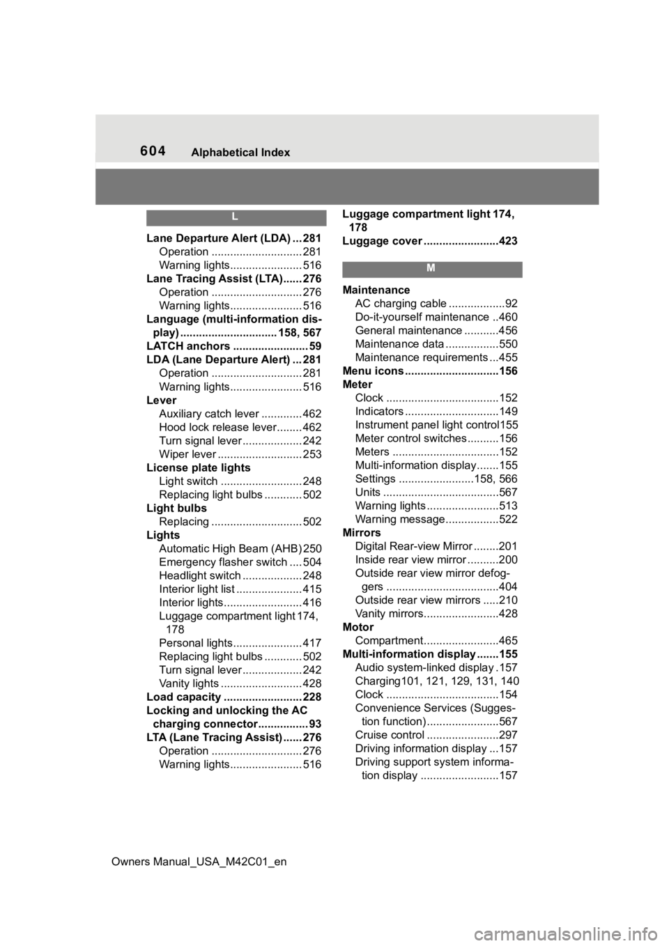
604Alphabetical Index
Owners Manual_USA_M42C01_en
L
Lane Departure A lert (LDA) ... 281
Operation ............................. 281
Warning lights....................... 516
Lane Tracing Assist (LTA)...... 276 Operation ............................. 276
Warning lights....................... 516
Language (multi-information dis- play) ............................... 158, 567
LATCH anchors ........................ 59
LDA (Lane Departure Alert) ... 281 Operation ............................. 281
Warning lights....................... 516
Lever Auxiliary catch lever ............. 462
Hood lock release lever........ 462
Turn signal lever ................... 242
Wiper lever ........................... 253
License plate lights Light switch .......................... 248
Replacing light bulbs ............ 502
Light bulbs Replacing ............................. 502
Lights Automatic High Beam (AHB) 250
Emergency flasher switch .... 504
Headlight switch ................... 248
Interior light list ..................... 415
Interior lights......................... 416
Luggage compartment light 174, 178
Personal lights...................... 417
Replacing light bulbs ............ 502
Turn signal lever ................... 242
Vanity lights .......................... 428
Load capacity ......................... 228
Locking and unlocking the AC charging c onnector................ 93
LTA (Lane Tracing Assist) ...... 276 Operation ............................. 276
Warning lights....................... 516 Luggage compartment light 174,
178
Luggage cover ........................423
M
Maintenance AC charging cable ..................92
Do-it-yourself maintenance ..460
General maintenance ...........456
Maintenance data .................550
Maintenance requirements ...455
Menu icons ..............................156
Meter Clock ....................................152
Indicators ..............................149
Instrument panel light control155
Meter control switches..........156
Meters ..................................152
Multi-information display.......155
Settings ........................158, 566
Units .....................................567
Warning lights .......................513
Warning message.................522
Mirrors Digital Rear-view Mirror ........201
Inside rear view mirror ..........200
Outside rear view mirror defog-gers ....................................404
Outside rear view mirrors .....210
Vanity mirrors........................428
Motor Compartment........................465
Multi-information display .......155
Audio system-linked display .157
Charging101, 121, 129, 131, 140
Clock ....................................154
Convenience Services (Sugges- tion function) .......................567
Cruise control .......................297
Driving information display ...157
Driving support system informa- tion display .........................157