TOYOTA CAMRY 1999 Service Repair Manual
CAMRY 1999
TOYOTA
TOYOTA
https://www.carmanualsonline.info/img/14/57448/w960_57448-0.png
TOYOTA CAMRY 1999 Service Repair Manual
Trending: air bleeding, transmission maintenance, index, child restraint, MPG, oil viscosity, maintenance
Page 4271 of 4592
G ELECTRICAL WIRING ROUTING
: Location of Connector Joining Wire Harness and Wire Harness
: Location of Ground Points
: Location of Splice Points
Page 4272 of 4592
G
Connector Joining Wire Harness and Wire Harness
2
76 5431 2 1
345 672
765431 2 1
34567
BO1BP1
CodeJoining Wire Harness and Wire Harness (Connector Location)
BO1Rear Door Wire LH and Floor Wire (Under the Left Center Pillar)
BP1Rear Door Wire RH and Floor No.2 Wire (Under the Right Center Pillar)
Page 4273 of 4592
G ELECTRICAL WIRING ROUTING
: Location of Connector Joining Wire Harness and Wire Harness
: Location of Splice Points
Page 4274 of 4592
G
Connector Joining Wire Harness and Wire Harness
132
1 2 312
2121 2 1
1221
BQ1BR1BV1YELLOW
BW1YELLOW
CodeJoining Wire Harness and Wire Harness (Connector Location)
BQ1Floor Wire and Seat No.1 Wire (Under the Driver's Seat)
BR1Floor No.2 Wire and Seat No.2 Wire (Under the Passenger's Seat)
BV1Floor Wire and Seat No.1 Wire (Under the Driver's Seat)
BW1Floor No.2 Wire and Seat No.2 Wire (Under the Passenger's Seat)
Page 4275 of 4592
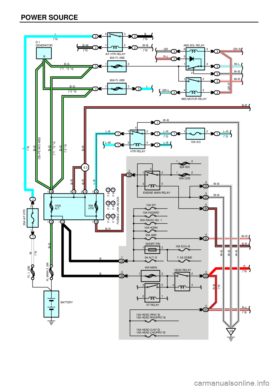
POWER SOURCE
1260A FL ABS
1260A FL ABS 3
3
1
1
2B2
2A1
2B33
3
3
1240A MAIN
EB B 1F1F2E1
A 1C1D1 E 33
1
1
1
2L4
2G3
2G4 2C5
2K63
3
3
3
3 16
5
1
1
4
4
1
3
4
1
3
1
44
3
2
3
2
5
2
5
2
3 2 B
B
BB±R L±WL±B L±R
L±B W±B B±G
B±G L
GR±LR±LGR GR±R
W± L
W±B
W± R
B±R
W±B
W±R
R
R±L
B±GB±G
B±G
B±G
B±R B±R
B±R
L±B
W±B
W±B
W±B R±B
BATTERY
FL MAIN 3. 0W
100A
ALT50A
HTR GENERATOR G 1
ABS SOL RELAY
AB S MOTOR RELAY
HTR RELAY
ENGINE MAIN RELAY
15A EFI
10A HAZARD
20A RADIO NO. 1
10A HORN
30A AM2
SHORT PIN
5A ALT±S
HEAD RELAY
15A HEAD (
RH)(
*9)
15A HEAD RH(
UPR)(
*8)
15A HEAD (
LH)(
*9)
15A HEAD LH(
UPR)(
*8)
(
5S±FE W/O ABS)
(
*7, *2 *4)
(
*2 *5)
(
*7, *2 *4)
(
*2 *5)
GR±R
30A CDS30A RDI
1 1
2 2
10A ECU±B
7. 5A DOME
(
*8)
(
*8)
(
*9)
112
1
10A A/C
2F4
W±B
B±R
12
3
25
1
ST RELAYL±R 5
13
22
2 2
2B
(
*6)
W±B
(
*6) B±W
(
*6) L
(
*6)
A/F HTR RELAY
1 1
W
(
*6) FL 1. 25B25A A/F HTR
F 4 BA, F 5
F 7
FUSIBLE LINK BLOCKE D, F 8C , F 6
F , F 9L
(
*6)
,
1 2(
*3)(
*3)
Page 4276 of 4592
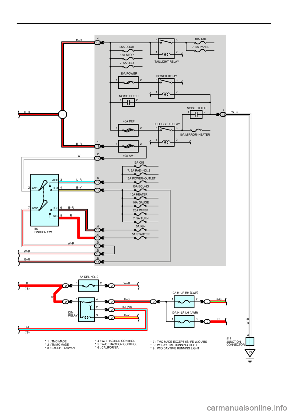
1230A POWER
1240A DEF
12
40A AM1 1B4
1B1
1K2
1K6
1K1
1K3
1K4
1K5
1B5
2
221J7
2
2
2
22
2 AM1
AM2 7 23
6 ACC
IG1
IG2
ST24
8I 1
12
IG 12
13 25A DOOR
15A STOP
7. 5A OBDTAI LL IGHT REL AY10A TAIL
7. 5A PANEL
POWER RELAY
NOISE FILTER
NOISE FILTER
DEFOGGER RELAY
10A MIRROR±HEATER
15A CIG
7. 5A RAD±NO. 2
15A POWER±OUTLET
15A ECU±IG
10A HEATER
10A GAUGE
25A WIPER
7. 5A TURN
5A IGN
5A STARTER
5A DRL NO. 2
DIM
RELAY10A H±LP RH (
LWR)
10A H±LP LH (
LWR)
JUNCTION
CONNECTOR IGNITION SW I16
J11 B±R
B±R
W B±R
W± B
L±R
B±Y
B±R
R1
1 5
1
5
1
5
13
2
3
2
2
2
3
2
* 1 : TMC MADE
* 2 : TMMK MADE
* 3 : EXCEPT TAIWAN* 4 : W/ TRACTION CONTROL
* 5 : W/ O TRACTI ON CONTROL W±R
R
R±L W±R
(
*8)
(
*8)14
2
3W±R
R±B
R±L(
*8)
R±YR±G
R
A
W±B
1A6
B±R
R
* 6 : CALIFORNIA* 7 : TMC MADE EXCEPT 5S±FE W/O ABS
* 8 : W/ DAYTIME RUNNING LIGHT
* 9 : W/O DAYTIME RUNNING LIGHT
Page 4277 of 4592
![TOYOTA CAMRY 1999 Service Repair Manual POWER SOURCE
HEAD RELAY [ENGINE ROOM J/B NO.2]
2±1 : Closed with the light control SW at HEAD position or the dimmer SW at FLASH position
Closed with the engine running and the parking brake pedal re TOYOTA CAMRY 1999 Service Repair Manual POWER SOURCE
HEAD RELAY [ENGINE ROOM J/B NO.2]
2±1 : Closed with the light control SW at HEAD position or the dimmer SW at FLASH position
Closed with the engine running and the parking brake pedal re](/img/14/57448/w960_57448-4276.png)
POWER SOURCE
HEAD RELAY [ENGINE ROOM J/B NO.2]
2±1 : Closed with the light control SW at HEAD position or the dimmer SW at FLASH position
Closed with the engine running and the parking brake pedal released (Parking brake SW off) (w/ Daytime Running
Light)
TAILLIGHT RELAY [INSTRUMENT PANEL J/B]
5±3 : Closed with the light control SW at TAIL or HEAD position
I16 IGNITION SW
2±3 : Closed with the ignition SW at ACC or ON position
2±4 : Closed with the ignition SW at ON or ST position
7±6 : Closed with the ignition SW at ON or ST position
7±8 : Closed with the ignition SW at ST position
: PARTS LOCATION
CodeSee PageCodeSee PageCodeSee Page
F4A26 (1MZ±FE)F7D26 (1MZ±FE)G126 (1MZ±FE)F4A28 (5S±FE)F7D28 (5S±FE)G128 (5S±FE)
F5B26 (1MZ±FE)F8E26 (1MZ±FE)I1630F5B28 (5S±FE)F8E28 (5S±FE)J1131
F6C26 (1MZ±FE)F9F26 (1MZ±FE)F6C28 (5S±FE)F9F28 (5S±FE)
: RELAY BLOCKS
CodeSee PageRelay Blocks (Relay Block Location)
124Engine Room R/B No.1 (Engine Compartment Left)
224Engine Room R/B No.2 (Near the Battery)
325Engine Room R/B No.3 (Radiator Upper Support RH)
: JUNCTION BLOCK AND WIRE HARNESS CONNECTOR
CodeSee PageJunction Block and Wire Harness (Connector Location)
1A
1B20Cowl Wire and J/B Instrument Panel J/B (Lower Finish Panel)1J20Cowl Wire and J/B Instrument Panel J/B (Lower Finish Panel)
1K
2A
2B
2C22Engine Room Main Wire and Engine Room J/B No.2 (Engine Compartment Left)
2F
gg(g)
2G
2K22Cowl Wire and Engine Room J/B No 2 (Engine Compartment Left)2L22Cowl Wire and Engine Room J/B No.2 (Engine Compartment Left)
: GROUND POINTS
CodeSee PageGround Points Location
EB36 (1MZ±FE)Left Radiator Side SupportEB38 (5S±FE)Left Radiator Side Support
IG40Instrument Panel Brace LH
: SPLICE POINTS
CodeSee PageWire Harness with Splice PointsCodeSee PageWire Harness with Splice Points
E336 (1MZ±FE)Cowl WireI142Cowl WireE338 (5S±FE)Cowl Wire
SERVICE HINTS
Page 4278 of 4592
1111
12
1
X234
X678
AA
AAAA
1
F4 (A) F5 (B) F6 (C) F7 (D) F8 (E)
ORANGEG1 I16 J11
(Hint : See Page 7)
F9 (F)
Page 4279 of 4592
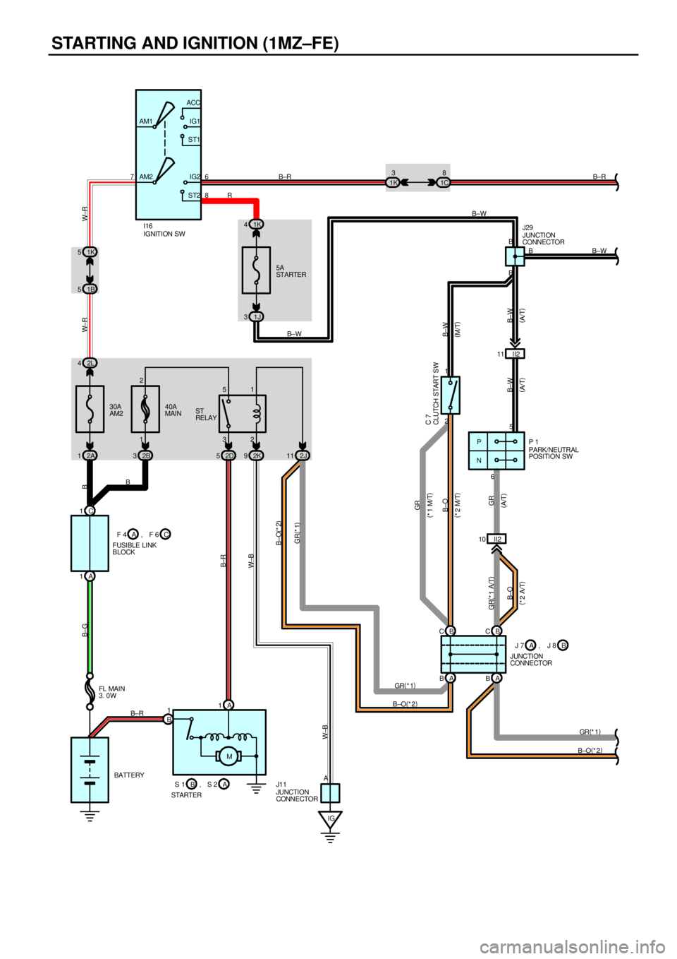
STARTING AND IGNITION (1MZ±FE)
2L 4
2A 1
IG M 1
B1
B±RB±R
B±G
B±RB
IGNITION SW
32 51
30A
AM2ST
RELAY
PARK/NEUTRAL
POSITION SW
BATTERY FL MAI N
3. 0WI16
P 1
AP
N5
6 2D 52K92J11 40A
MAIN 76
8 AM2 AM1ACC
IG1
ST1
IG2
ST2
5A
ST ARTER
1J 31K 4
1B 51K 5
W± R
2B 3
JUNCTION
CONNECTOR J1 1
W±B
B
AB
BB±W
GR(
*1) B
GR(
*1 A/T)
GR
B±WW±R
B±R
(
A/T)
JUNCTION
CONNECTOR J29
C 1
B C A 1
A BAB 1K3
1C8
II2 11
2 1
II2 10
B±O(
*2) R
B±W
GR(
*1)
B±O(
*2)
B±O B±W GR(
*1) B±O(
*2)
W±B
B±O(
*2 M/T)(
M/T)
(
*2 A/T)CLUTCH START S W C 7
B±W
(
A/T)
1 2
J 7
JUNCTION
CONNECTORB A, J 8
S 1
STARTERA B, S 2 F 4
FUSIBLE LINK
BLOCKC A, F 6
B C
(
A/T) GR
(
*1 M/T)
B±W
Page 4280 of 4592
II3 12
2 1 A A
B±R B±R L
22 1 A
B±R Y
12 1 A
B±R G
10A
9
B±R
A
2 1
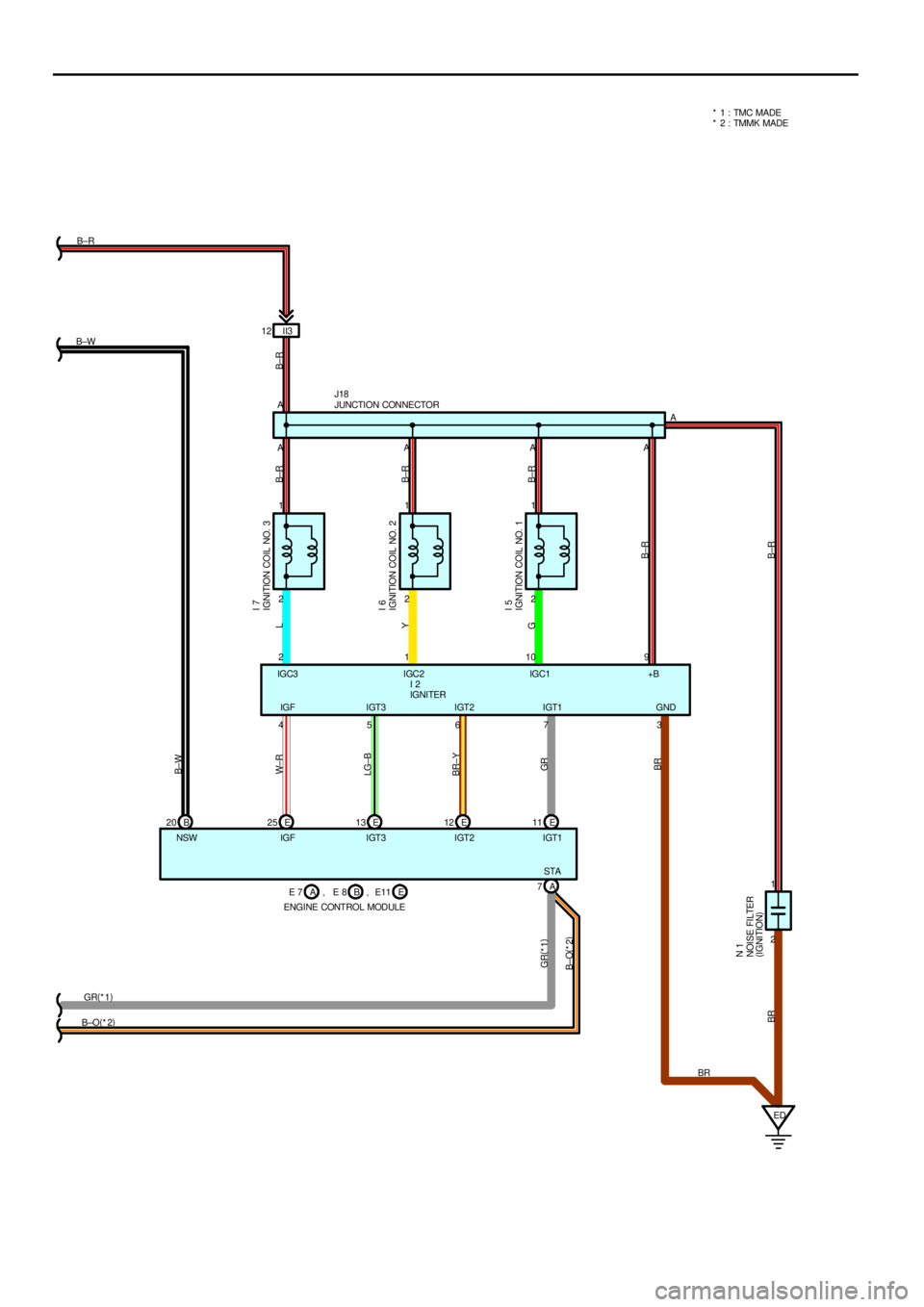
B±R IGNITION COIL NO. 3 I 7
IGNITION COIL NO. 2 I 6
IGNITION COIL NO. 1 I 5
NOISE FILTER
(
IGNITION) N 1
ED 3 7 6 5 4 B±R
GR(
*1)
W± R
LG±B
BR±Y
GR
BR
BR
JUNCTION CONNECTOR J18
IGNITER I 2
IGF I GT3 I GT2 I GT1 GND
NSW IGF IGT3 IGT2 IGT1IGC3 IGC2 IGC1 +B
B±O(
*2)STA* 1 : TMC MADE
* 2 : TMMK MADE
E 25 E13 E12 E11
A 7
B±W
E 7
ENGINE CONTROL MODULEB A, E 8 E, E11 B 20 B±W
GR(
*1)
B±O(
*2)
BR
Trending: clutch starter switch, heater, transmission maintenance, remove the head, automatic transaxle fluid, warning, air bleeding


![TOYOTA CAMRY 1999 Service Repair Manual POWER SOURCE
HEAD RELAY [ENGINE ROOM J/B NO.2]
2±1 : Closed with the light control SW at HEAD position or the dimmer SW at FLASH position
Closed with the engine running and the parking brake pedal re TOYOTA CAMRY 1999 Service Repair Manual POWER SOURCE
HEAD RELAY [ENGINE ROOM J/B NO.2]
2±1 : Closed with the light control SW at HEAD position or the dimmer SW at FLASH position
Closed with the engine running and the parking brake pedal re](/img/14/57448/w960_57448-4276.png)


