TOYOTA CAMRY 2010 XV40 / 8.G Owners Manual
Manufacturer: TOYOTA, Model Year: 2010, Model line: CAMRY, Model: TOYOTA CAMRY 2010 XV40 / 8.GPages: 538, PDF Size: 9.22 MB
Page 411 of 538
409
4-3. Do-it-yourself maintenance
4
Maintenance and care
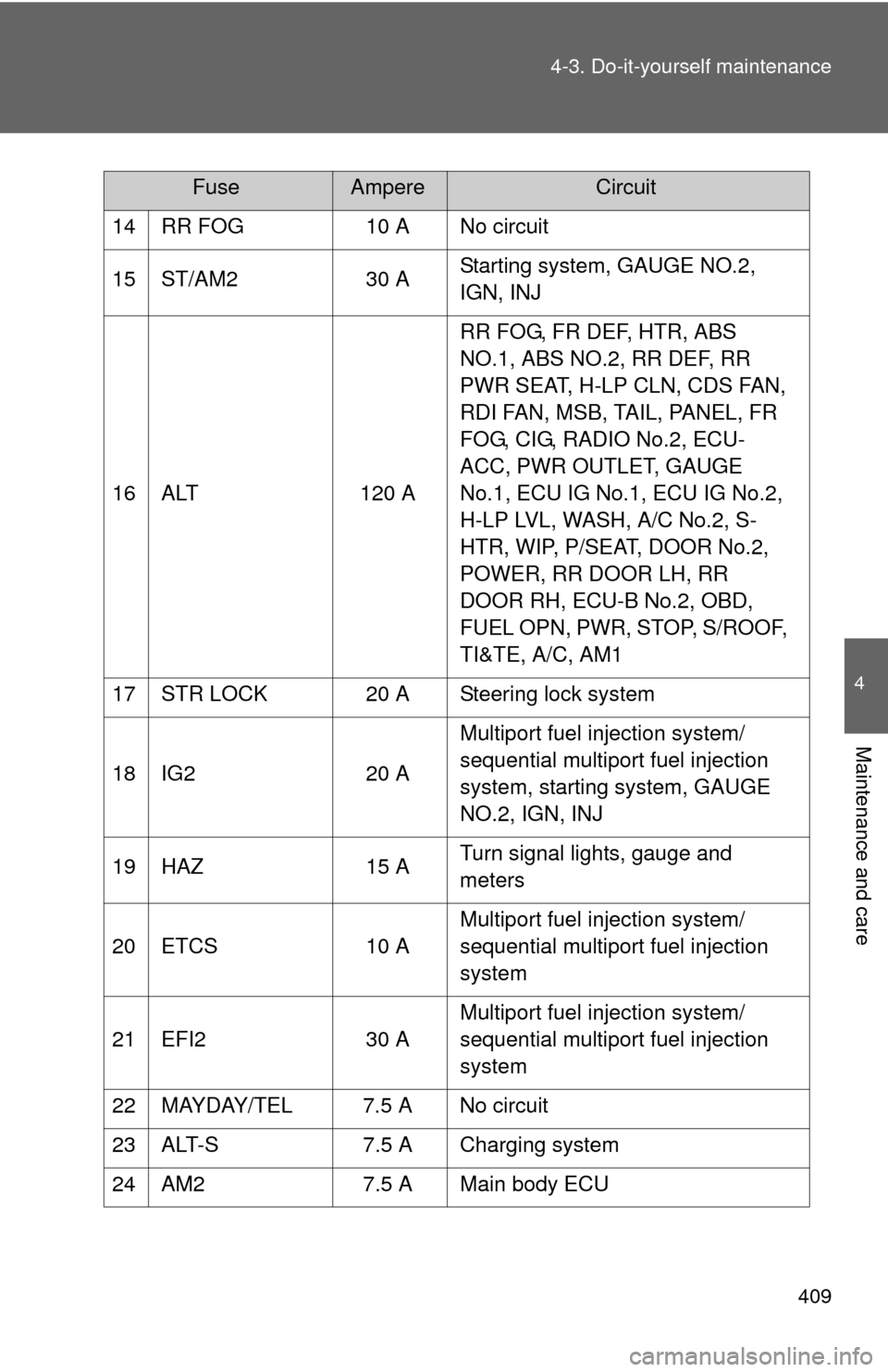
14 RR FOG
10 A No circuit
15 ST/AM2 30 AStarting system, GAUGE NO.2,
IGN, INJ
16 ALT 120 ARR FOG, FR DEF, HTR, ABS
NO.1, ABS NO.2, RR DEF, RR
PWR SEAT, H-LP CLN, CDS FAN,
RDI FAN, MSB, TAIL, PANEL, FR
FOG, CIG, RADIO No.2, ECU-
ACC, PWR OUTLET, GAUGE
No.1, ECU IG No.1, ECU IG No.2,
H-LP LVL, WASH, A/C No.2, S-
HTR, WIP, P/SEAT, DOOR No.2,
POWER, RR DOOR LH, RR
DOOR RH, ECU-B No.2, OBD,
FUEL OPN, PWR, STOP, S/ROOF,
TI&TE, A/C, AM1
17 STR LOCK 20 A Steering lock system
18 IG2 20 AMultiport fuel injection system/
sequential multiport fuel injection
system, starting system, GAUGE
NO.2, IGN, INJ
19 HAZ 15 ATurn signal lights, gauge and
meters
20 ETCS 10 AMultiport fuel injection system/
sequential multiport fuel injection
system
21 EFI2 30 AMultiport fuel injection system/
sequential multiport fuel injection
system
22 MAYDAY/TEL 7.5 A No circuit
23 ALT-S 7.5 A Charging system
24 AM2 7.5 A Main body ECU
FuseAmpereCircuit
Page 412 of 538
410 4-3. Do-it-yourself maintenance
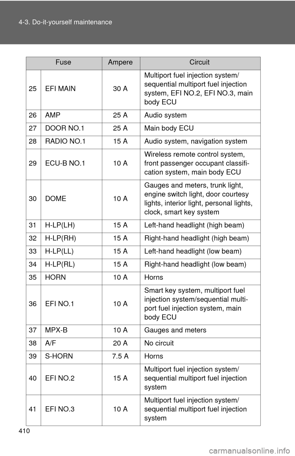
25 EFI MAIN 30 AMultiport fuel injection system/
sequential multiport fuel injection
system, EFI NO.2, EFI NO.3, main
body ECU
26 AMP 25 A Audio system
27 DOOR NO.1 25 A Main body ECU
28 RADIO NO.1 15 A Audio system, navigation system
29 ECU-B NO.1 10 A Wireless remote control system,
front passenger occupant classifi-
cation system, main body ECU
30 DOME 10 AGauges and meters, trunk light,
engine switch light, door courtesy
lights, interior light, personal lights,
clock, smart key system
31 H-LP(LH) 15 A Left-hand headlight (high beam)
32 H-LP(RH) 15 A Right-hand headlight (high beam)
33 H-LP(LL) 15 A Left-hand headlight (low beam)
34 H-LP(RL) 15 A Right-hand headlight (low beam)
35 HORN 10 A Horns
36 EFI NO.1 10 ASmart key system, multiport fuel
injection system/sequential multi-
port fuel injection system, main
body ECU
37 MPX-B 10 A Gauges and meters
38 A/F 20 A No circuit
39 S-HORN 7.5 A Horns
40 EFI NO.2 15 AMultiport fuel injection system/
sequential multiport fuel injection
system
41 EFI NO.3 10 AMultiport fuel injection system/
sequential multiport fuel injection
system
FuseAmpereCircuit
Page 413 of 538
411
4-3. Do-it-yourself maintenance
4
Maintenance and care
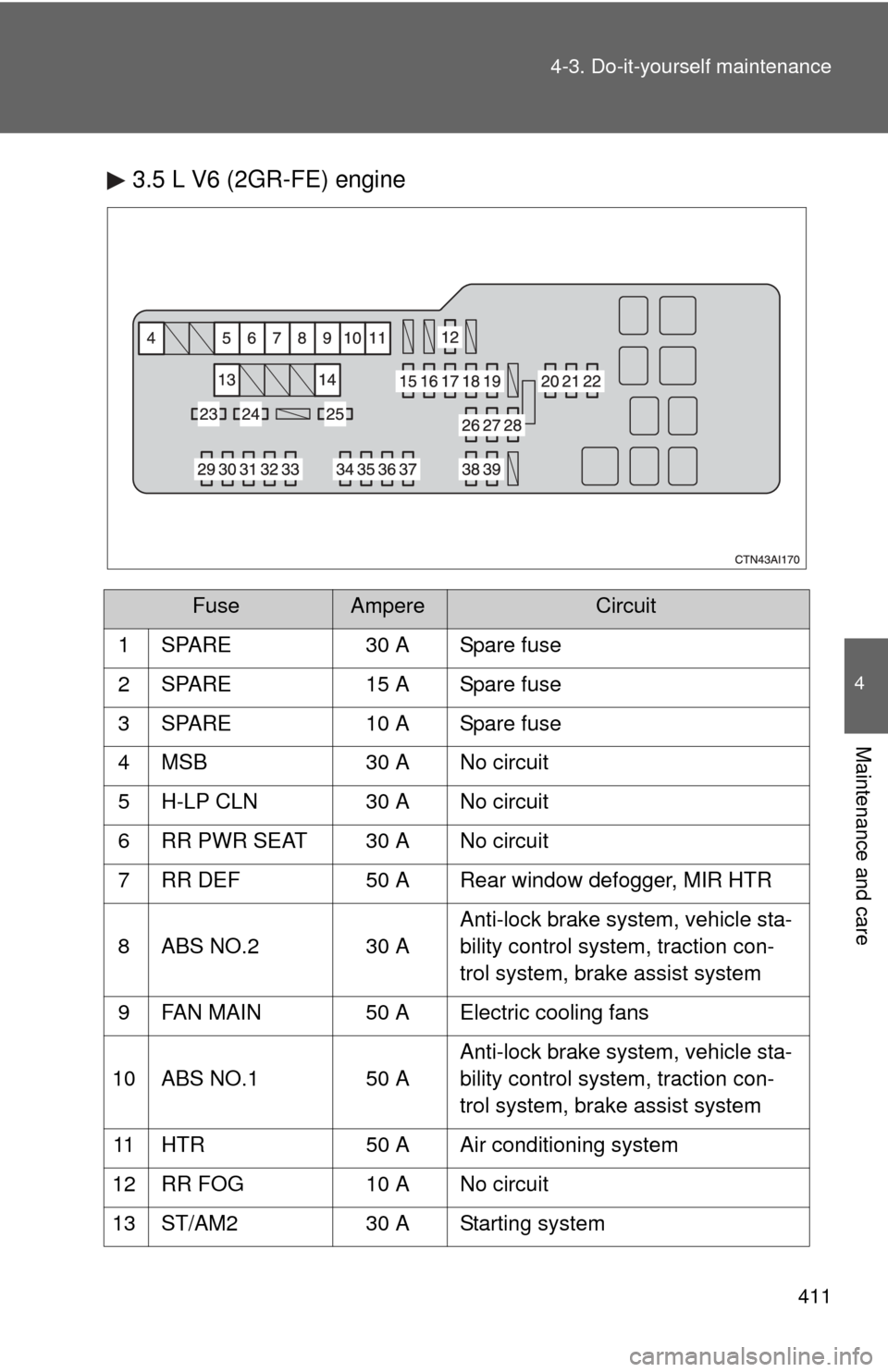
3.5 L V6 (2GR-FE) engine
FuseAmpereCircuit
1 SPARE 30 A Spare fuse
2 SPARE 15 A Spare fuse
3 SPARE 10 A Spare fuse
4 MSB 30 A No circuit
5 H-LP CLN 30 A No circuit
6 RR PWR SEAT 30 A No circuit
7 RR DEF 50 A Rear window defogger, MIR HTR
8 ABS NO.2 30 A Anti-lock brake system, vehicle sta-
bility control system, traction con-
trol system, brake assist system
9 FAN MAIN 50 A Electric cooling fans
10 ABS NO.1 50 A Anti-lock brake system, vehicle sta-
bility control system, traction con-
trol system, brake assist system
11 HTR 50 A Air conditioning system
12 RR FOG 10 A No circuit
13 ST/AM2 30 A Starting system
Page 414 of 538
412 4-3. Do-it-yourself maintenance
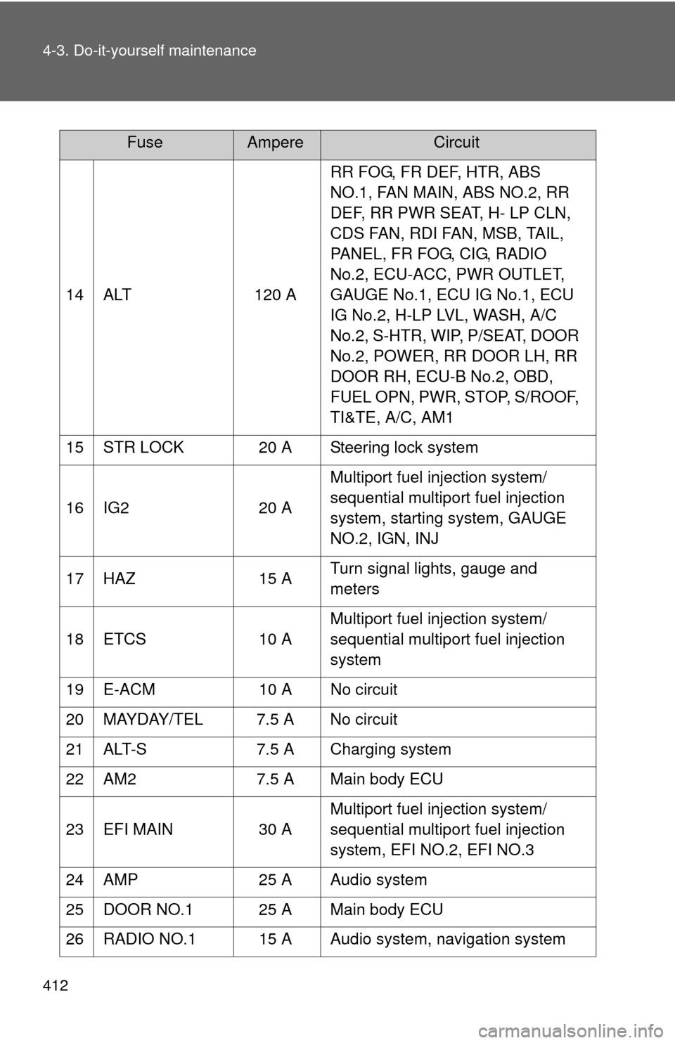
14 ALT120 ARR FOG, FR DEF, HTR, ABS
NO.1, FAN MAIN, ABS NO.2, RR
DEF, RR PWR SEAT, H- LP CLN,
CDS FAN, RDI FAN, MSB, TAIL,
PANEL, FR FOG, CIG, RADIO
No.2, ECU-ACC, PWR OUTLET,
GAUGE No.1, ECU IG No.1, ECU
IG No.2, H-LP LVL, WASH, A/C
No.2, S-HTR, WIP, P/SEAT, DOOR
No.2, POWER, RR DOOR LH, RR
DOOR RH, ECU-B No.2, OBD,
FUEL OPN, PWR, STOP, S/ROOF,
TI&TE, A/C, AM1
15 STR LOCK 20 A Steering lock system
16 IG2 20 AMultiport fuel injection system/
sequential multiport fuel injection
system, starting system, GAUGE
NO.2, IGN, INJ
17 HAZ 15 ATurn signal lights, gauge and
meters
18 ETCS 10 AMultiport fuel injection system/
sequential multiport fuel injection
system
19 E-ACM 10 A No circuit
20 MAYDAY/TEL 7.5 A No circuit
21 ALT-S 7.5 A Charging system
22 AM2 7.5 A Main body ECU
23 EFI MAIN 30 AMultiport fuel injection system/
sequential multiport fuel injection
system, EFI NO.2, EFI NO.3
24 AMP 25 A Audio system
25 DOOR NO.1 25 A Main body ECU
26 RADIO NO.1 15 A Audio system, navigation system
FuseAmpereCircuit
Page 415 of 538
413
4-3. Do-it-yourself maintenance
4
Maintenance and care
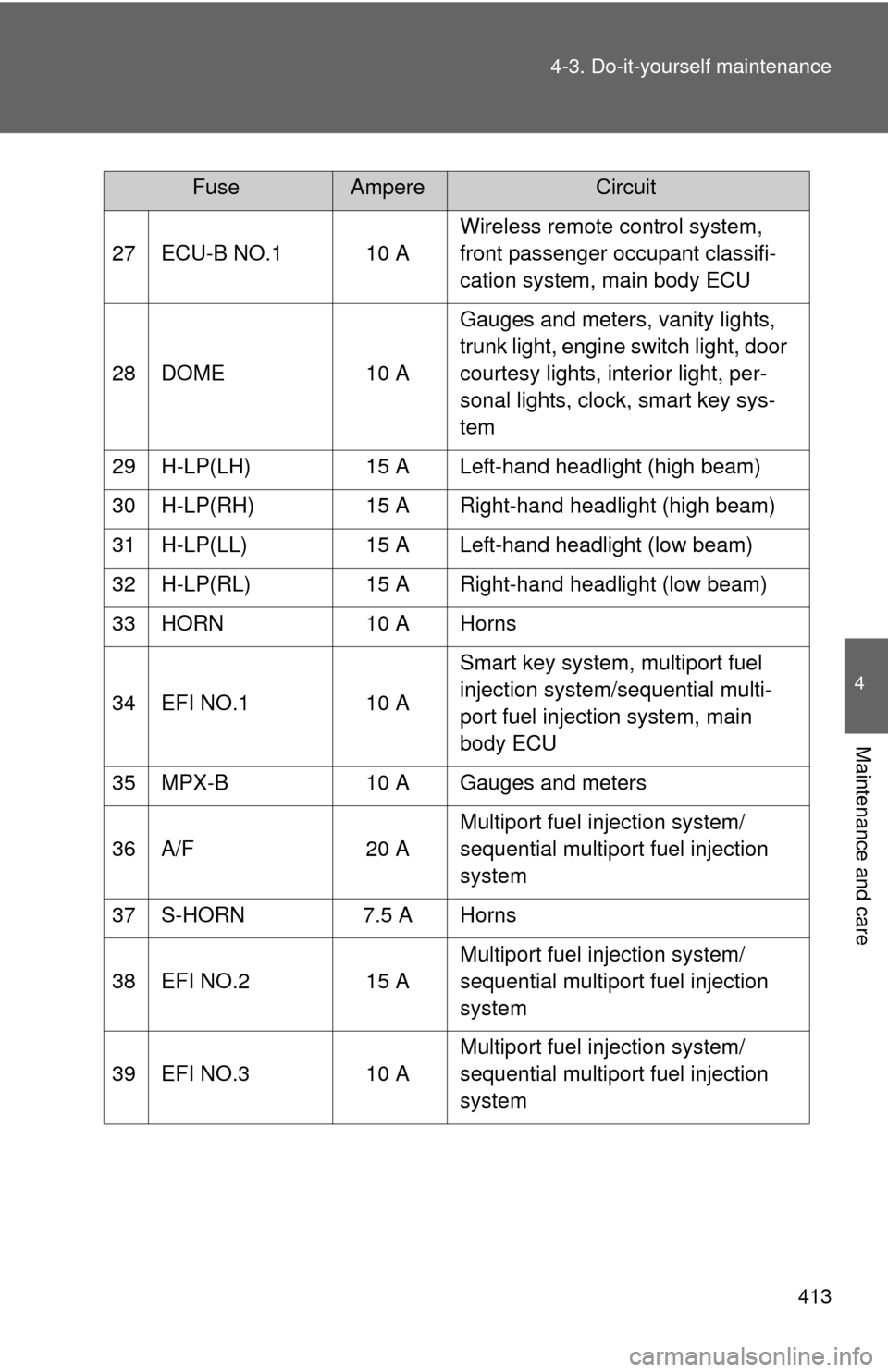
27 ECU-B NO.1 10 A
Wireless remote control system,
front passenger occupant classifi-
cation system, main body ECU
28 DOME 10 A Gauges and meters, vanity lights,
trunk light, engine switch light, door
courtesy lights, interior light, per-
sonal lights, clock, smart key sys-
tem
29 H-LP(LH) 15 A Left-hand headlight (high beam)
30 H-LP(RH) 15 A Right-hand headlight (high beam)
31 H-LP(LL) 15 A Left-hand headlight (low beam)
32 H-LP(RL) 15 A Right-hand headlight (low beam)
33 HORN 10 A Horns
34 EFI NO.1 10 A Smart key system, multiport fuel
injection system/sequential multi-
port fuel injection system, main
body ECU
35 MPX-B 10 A Gauges and meters
36 A/F 20 A Multiport fuel injection system/
sequential multiport fuel injection
system
37 S-HORN 7.5 A Horns
38 EFI NO.2 15 A Multiport fuel injection system/
sequential multiport fuel injection
system
39 EFI NO.3 10 A Multiport fuel injection system/
sequential multiport fuel injection
system
FuseAmpereCircuit
Page 416 of 538
414 4-3. Do-it-yourself maintenance
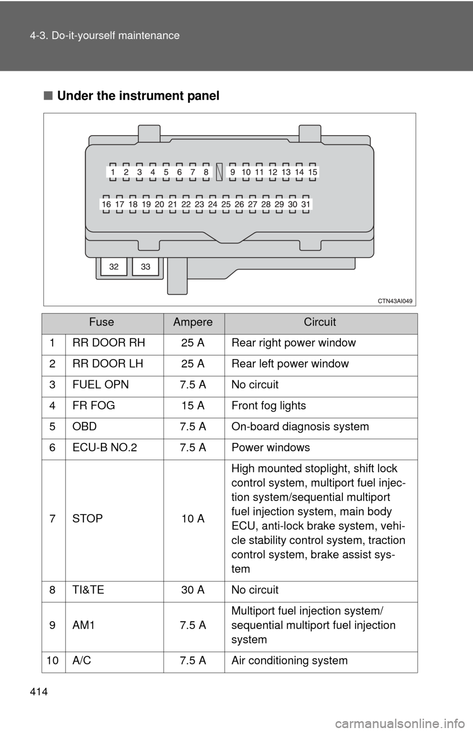
■Under the instrument panel
FuseAmpereCircuit
1 RR DOOR RH 25 A Rear right power window
2 RR DOOR LH 25 A Rear left power window
3 FUEL OPN 7.5 A No circuit
4 FR FOG 15 A Front fog lights
5 OBD 7.5 A On-board diagnosis system
6 ECU-B NO.2 7.5 A Power windows
7 STOP 10 A High mounted stoplight, shift lock
control system, multiport fuel injec-
tion system/sequential multiport
fuel injection system, main body
ECU, anti-lock brake system, vehi-
cle stability control system, traction
control system, brake assist sys-
tem
8 TI&TE 30 A No circuit
9 AM1 7.5 A Multiport fuel injection system/
sequential multiport fuel injection
system
10 A/C 7.5 A Air conditioning system
Page 417 of 538
415
4-3. Do-it-yourself maintenance
4
Maintenance and care
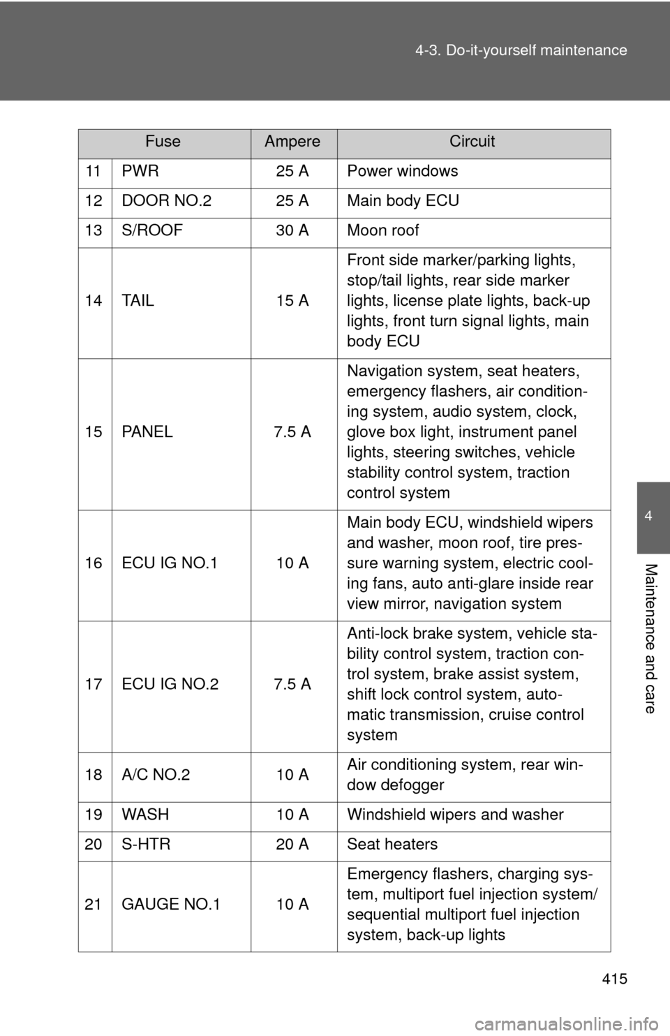
11 PWR
25 A Power windows
12 DOOR NO.2 25 A Main body ECU
13 S/ROOF 30 A Moon roof
14 TAIL 15 AFront side marker/parking lights,
stop/tail lights, rear side marker
lights, license plate lights, back-up
lights, front turn signal lights, main
body ECU
15 PANEL 7.5 ANavigation system, seat heaters,
emergency flashers, air condition-
ing system, audio system, clock,
glove box light, instrument panel
lights, steering switches, vehicle
stability control system, traction
control system
16 ECU IG NO.1 10 A Main body ECU, windshield wipers
and washer, moon roof, tire pres-
sure warning system, electric cool-
ing fans, auto anti-glare inside rear
view mirror, navigation system
17 ECU IG NO.2 7.5 A Anti-lock brake system, vehicle sta-
bility control system, traction con-
trol system, brake assist system,
shift lock control system, auto-
matic transmission, cruise control
system
18 A/C NO.2 10 AAir conditioning system, rear win-
dow defogger
19 WASH 10 A Windshield wipers and washer
20 S-HTR 20 A Seat heaters
21 GAUGE NO.1 10 A Emergency flashers, charging sys-
tem, multiport fuel injection system/
sequential multiport fuel injection
system, back-up lights
FuseAmpereCircuit
Page 418 of 538
416 4-3. Do-it-yourself maintenance
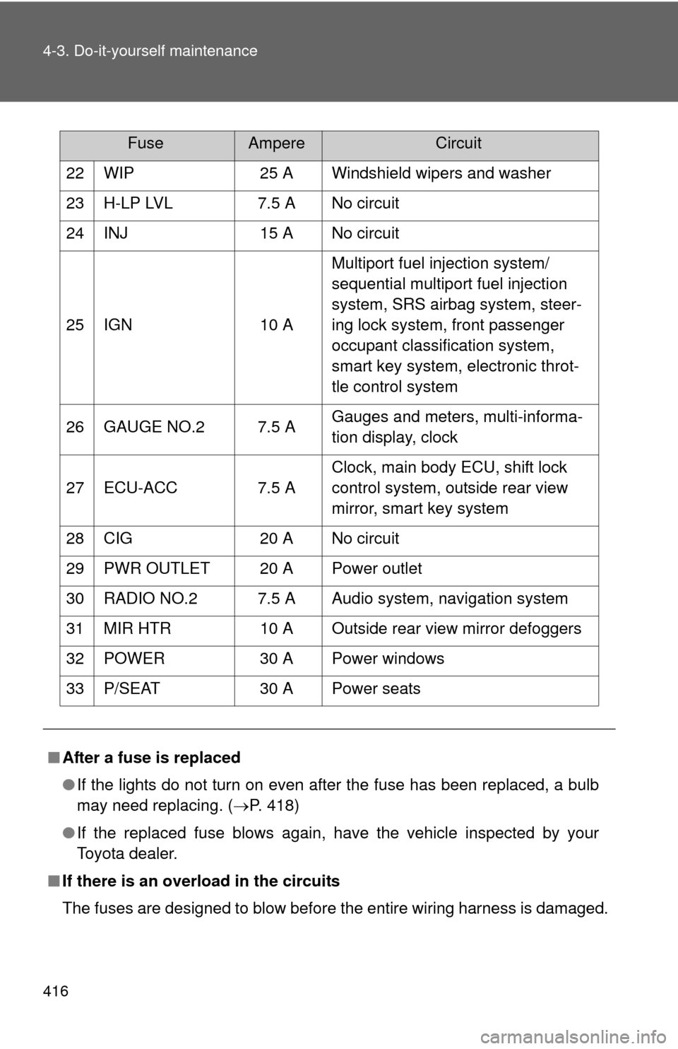
22 WIP25 A Windshield wipers and washer
23 H-LP LVL 7.5 A No circuit
24 INJ 15 A No circuit
25 IGN 10 AMultiport fuel injection system/
sequential multiport fuel injection
system, SRS airbag system, steer-
ing lock system, front passenger
occupant classification system,
smart key system, electronic throt-
tle control system
26 GAUGE NO.2 7.5 A Gauges and meters, multi-informa-
tion display, clock
27 ECU-ACC 7.5 A Clock, main body ECU, shift lock
control system, outside rear view
mirror, smart key system
28 CIG 20 A No circuit
29 PWR OUTLET 20 A Power outlet
30 RADIO NO.2 7.5 A Audio system, navigation system
31 MIR HTR 10 A Outside rear view mirror defoggers
32 POWER 30 A Power windows
33 P/SEAT 30 A Power seats
■ After a fuse is replaced
●If the lights do not turn on even after the fuse has been replaced, a bulb
may need replacing. ( P. 418)
● If the replaced fuse blows again, have the vehicle inspected by your
Toyota dealer.
■ If there is an overload in the circuits
The fuses are designed to blow before the entire wiring harness is damaged.
FuseAmpereCircuit
Page 419 of 538
417
4-3. Do-it-yourself maintenance
4
Maintenance and care
CAUTION
■
To prevent system breakdowns and vehicle fire
Observe the following precautions.
Failing to do so may cause damage, and possibly a fire or injury.
●Never use a fuse of a higher amperage rating than indicated, or use any
other object in place of a fuse.
● Always use a genuine Toyota fuse or equivalent.
Never replace a fuse with a wire, even as a temporary fix.
This can cause extensive damage or even fire.
● Do not modify the fuse or the fuse box.
NOTICE
■Before replacing fuses
Have the cause of electrical overload determined and repaired by your
Toyota dealer, as soon as possible.
Page 420 of 538
418
4-3. Do-it-yourself maintenance
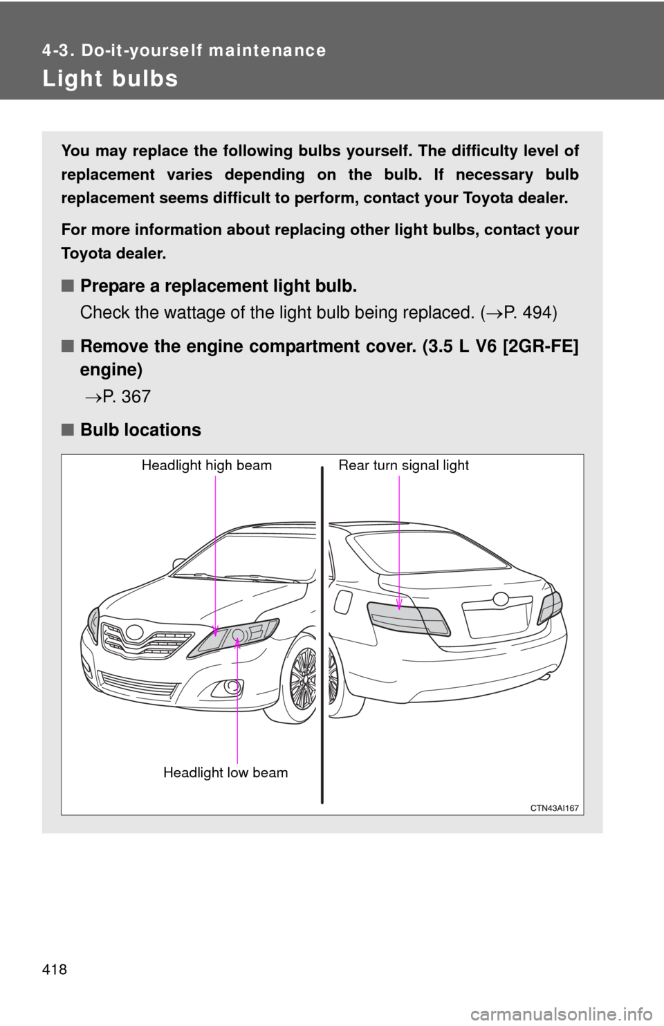
Light bulbs
You may replace the following bulbs yourself. The difficulty level of
replacement varies depending on the bulb. If necessary bulb
replacement seems difficult to perfor m, contact your Toyota dealer.
For more information about replacing other light bulbs, contact your
Toyota dealer.
■ Prepare a replacement light bulb.
Check the wattage of the light bulb being replaced. ( P. 494)
■ Remove the engine compartment cover. (3.5 L V6 [2GR-FE]
engine)
P. 3 6 7
■ Bulb locations
Headlight high beam
Headlight low beam
Rear turn signal light