navigation TOYOTA CAMRY 2020 Accessories, Audio & Navigation (in English)
[x] Cancel search | Manufacturer: TOYOTA, Model Year: 2020, Model line: CAMRY, Model: TOYOTA CAMRY 2020Pages: 350, PDF Size: 8.63 MB
Page 191 of 350
191
3. PANORAMIC VIEW MONITOR
PERIPHERAL MONITORING SYSTEM
6
4. CHECKING THE SIDES OF THE VEHICLE
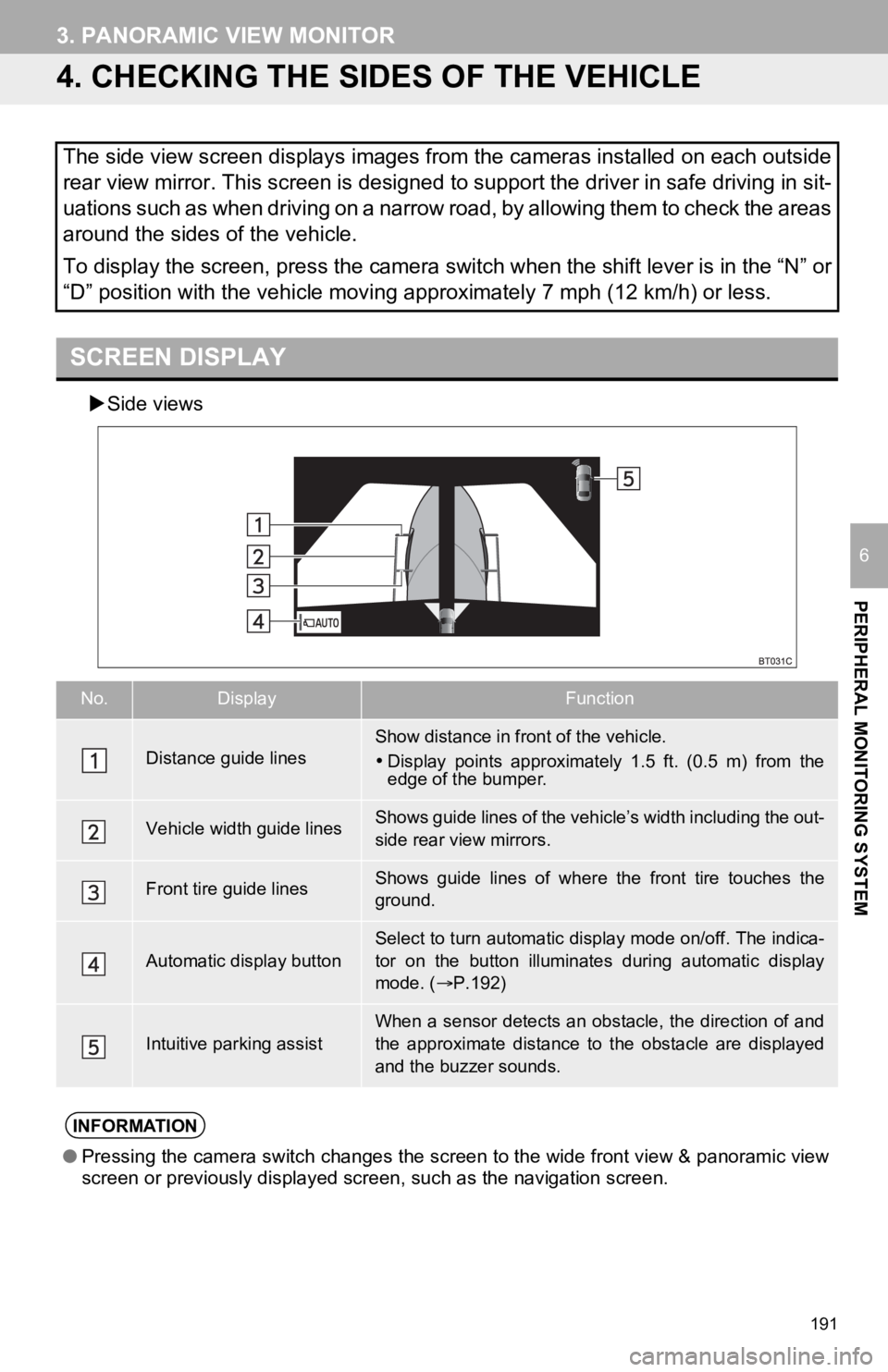
Side views
The side view screen displays images from the cameras installed on each outside
rear view mirror. This screen is designed to support the driver in safe driving in sit-
uations such as when driving on a narrow road, by allowing them to check the areas
around the sides of the vehicle.
To display the screen, press the camera switch when the shift l ever is in the “N” or
“D” position with the vehicle moving approximately 7 mph (12 km /h) or less.
SCREEN DISPLAY
No.DisplayFunction
Distance guide linesShow distance in front of the vehicle.
Display points approximately 1.5 ft. (0.5 m) from the
edge of the bumper.
Vehicle width guide linesShows guide lines of the vehicl e’s width including the out-
side rear view mirrors.
Front tire guide linesShows guide lines of where the front tire touches the
ground.
Automatic display button
Select to turn automatic display mode on/off. The indica-
tor on the button illuminates during automatic display
mode. ( P.192)
Intuitive parking assistWhen a sensor detects an obstacle, the direction of and
the approximate distance to the obstacle are displayed
and the buzzer sounds.
INFORMATION
● Pressing the camera switch changes the screen to the wide front view & panoramic view
screen or previously displayed screen, such as the navigation s creen.
Page 233 of 350
233
1. PHONE OPERATION (HANDS-FREE SYSTEM FOR CELLULAR PHONES)
PHONE
7
■EDITING QUICK REPLY MESSAG-
ES
1Select corresponding to the de-
sired message to edit.
2Select “OK” when editing is complet-
ed.
*: Premium Audio only
■CALLING FROM E-MAIL/SMS/MMS
MESSAGE DISPLAY
1Display the message screen.
(P.230)
2Select the desired message.
3Select , or press the switch on
the steering wheel.
If there are 2 or more phone numbers,
select the desired number.
4Check that the “Dialing...” screen is
displayed.
This operation cannot be performed
while driving.
INFORMATION
● To reset the edit quick reply messages,
select “Default”.
● Quick Message 1 (“I am driving and
will arrive in approximately [ETA]
minutes.”)*:
This message cannot be edited and will
automatically fill in [ETA] with the
navigation calculated estimated time of
arrival on the confirm message screen.
If there are waypoints set, [ETA] to the
next waypoint will be shown.
If there is no route currently set in the
navigation system, Quick Message 1
cannot be selected.
● Depending on the type of Bluetooth
®
phone used for receiving messages,
reply function may not be used.
CALLING THE MESSAGE
SENDER
Calls can be made to an e-mail/SMS/
MMS message sender’s phone num-
ber.
This operation can be performed while
driving.
Page 252 of 350
252
1. QUICK REFERENCE ................... 254
MAP SCREEN ..................................... 254
2. MAP SCREEN OPERATION ....... 256
CURRENT POSITION DISPLAY ......... 256
MAP SCALE ........................................ 256
ORIENTATION OF THE MAP ............. 257
MAP SCROLL OPERATION................ 258
DISPLAYING INFORMATION ABOUT THE ICON WHERE
THE CURSOR IS SET ...................... 258
STANDARD MAP ICONS .................... 259
3. MAP OPTIONS OPERATION ...... 260
SWITCHING THE MAP MODE............ 260
SELECTING THE POI*2 ICONS .......... 262
ROUTE TRACE ................................... 263
4. TRAFFIC INFORMATION ............ 264
DISPLAYING TRAFFIC INFORMATION ON THE MAP .......... 266
1. DESTINATION SEARCH OPERATION ............................. 267
SELECTING SEARCH AREA .............. 269
SETTING HOME AS
DESTINATION................................... 269
SEARCHING BY KEYWORD............... 269
SEARCHING BY FAVORITES LIST ................................................... 270
SEARCHING BY Destination Assist ................................................. 270
SEARCHING BY RECENT DESTINATIONS ................................ 270
SEARCHING BY EMERGENCY .......... 271
SEARCHING BY CONTACT ................ 271
SEARCHING BY ADDRESS ................ 271
SEARCHING BY POINT OF INTEREST ......................................... 272
ONE-TOUCH SETTING HOME/ FAVORITE AS A DESTINATION ...... 274
2. STARTING ROUTE GUIDANCE ....... ....................... .. 276
CONFIRM DESTINATION
SCREEN ............................................ 277
ROUTE OVERVIEW SCREEN ............ 277
A ROUTE FROM THE Cloud ............... 280
1BASIC OPERATION2DESTINATION SEARCH
8
NAVIGATION SYSTEM*1
Page 253 of 350
8
253
4
5
6
7
9
1
2
3
8
1. ROUTE GUIDANCE SCREEN ..... 281
SCREEN FOR ROUTE GUIDANCE ....................................... 281
LANE RECOMMENDATION ............... 282
DURING FREEWAY DRIVING............ 282
WHEN APPROACHING AN INTERSECTION ............................... 284
TURN LIST SCREEN .......................... 285
TURN-BY-TURN ARROW SCREEN ........................................... 285
2. TYPICAL VOICE GUIDANCE PROMPTS.................................. 286
3. ROUTE OPTIONS OPERATION .............................. 287
REORDERING DESTINATIONS ......... 287
SETTING ROUTE
PREFERENCES ............................... 288
SELECTING ROUTE TYPE ................ 288
DETOUR SETTING ............................. 289
ADJACENT ROAD .............................. 290
1. MEMORY POINTS SETTINGS ................................. 291
SETTING UP HOME ........................... 292
SETTING UP FAVORITES LIST ......... 293
SETTING UP AREAS TO AVOID ........ 294
1. DETAILED NAVIGATIONSETTINGS ................................. 296
SCREENS FOR NAVIGATION
SETTINGS ........................................ 296
2. TRAFFIC SETTINGS................... 300
SCREEN FOR TRAFFIC SETTINGS ........................................ 300
AVOID TRAFFIC................................. 301
MY TRAFFIC ROUTES ....................... 302
3. USE OF INFORMATION ACCUMULATED BY
NAVIGATION SYSTEM ............ 305
1. GPS (GLOBAL POSITIONING SYSTEM) .................... ............... 306
LIMITATIONS OF THE
NAVIGATION SYSTEM..................... 306
2. MAP DATABASE VERSION AND COVERED AREA ............. 308
MAP INFORMATION ........................... 308
TEMPORARY UPDATES OF THE
MAP ................................................... 308
3ROUTE GUIDANCE
4MEMORY POINTS
5SETUP
6TIPS FOR THE
NAVIGATION SYSTEM
NAVIGATION SYSTEM*1
*1: Premium Audio only
*2: Point of Interest
Page 255 of 350
255
1. BASIC OPERATION
NAVIGATION SYSTEM
8
Speed limit iconIndicates the speed limit on the current road. The
display of the speed limit icon can be set to on/off.260
Route informa-
tion bar
Displays the distance with the estimated travel
time/arrival time to the destination. The route in-
formation bar fills from left to right as the vehicle
progresses on the route.
282
Delete destina-
tion buttonSelect to delete destinations.
No.NameFunctionPage
INFORMATION
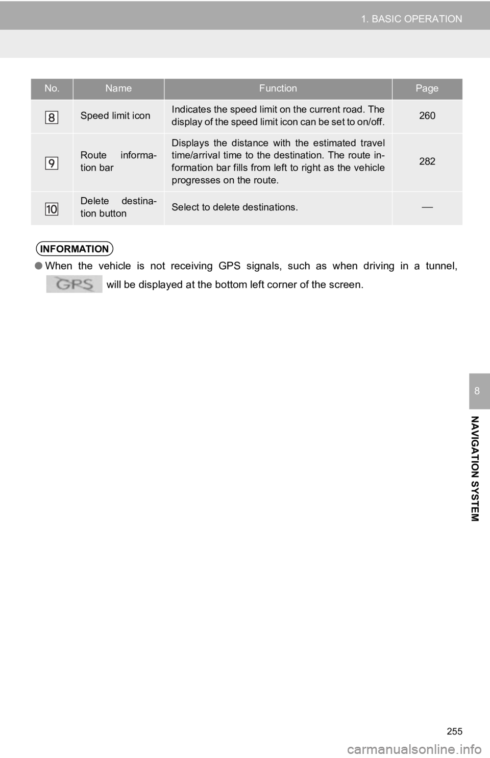
● When the vehicle is not receiving GPS signals, such as when dri ving in a tunnel,
will be displayed at the bottom left corner of the screen.
Page 257 of 350
257
1. BASIC OPERATION
NAVIGATION SYSTEM
8
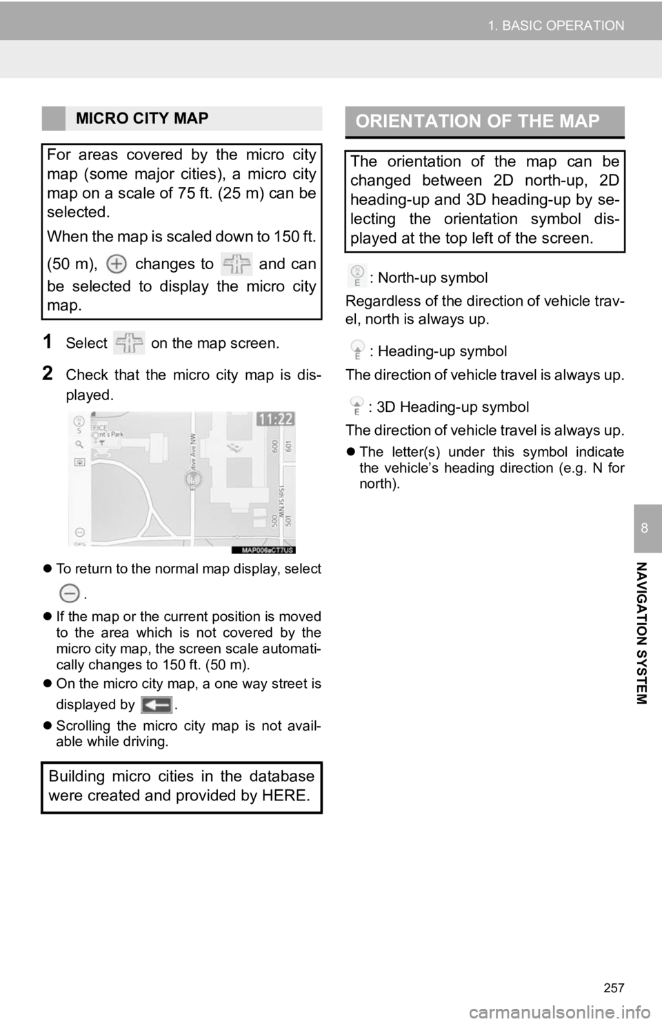
1Select on the map screen.
2Check that the micro city map is dis-
played.
To return to the normal map display, select
.
If the map or the current position is moved
to the area which is not covered by the
micro city map, the screen scale automati-
cally changes to 150 ft. (50 m).
On the micro city map, a one way street is
displayed by .
Scrolling the micro city map is not avail-
able while driving.
: North-up symbol
Regardless of the direction of vehicle trav-
el, north is always up.
: Heading-up symbol
The direction of vehicle travel is always up.
: 3D Heading-up symbol
The direction of vehicle travel is always up.
The letter(s) under this symbol indicate
the vehicle’s heading direction (e.g. N for
north).
MICRO CITY MAP
For areas covered by the micro city
map (some major cities), a micro city
map on a scale of 75 ft. (25 m) can be
selected.
When the map is scaled down to 150 ft.
(50 m), changes to and can
be selected to display the micro city
map.
Building micro cities in the database
were created and provided by HERE.ORIENTATION OF THE MAP
The orientation of the map can be
changed between 2D north-up, 2D
heading-up and 3D heading-up by se-
lecting the orientation symbol dis-
played at the top left of the screen.
Page 259 of 350
259
1. BASIC OPERATION
NAVIGATION SYSTEM
8
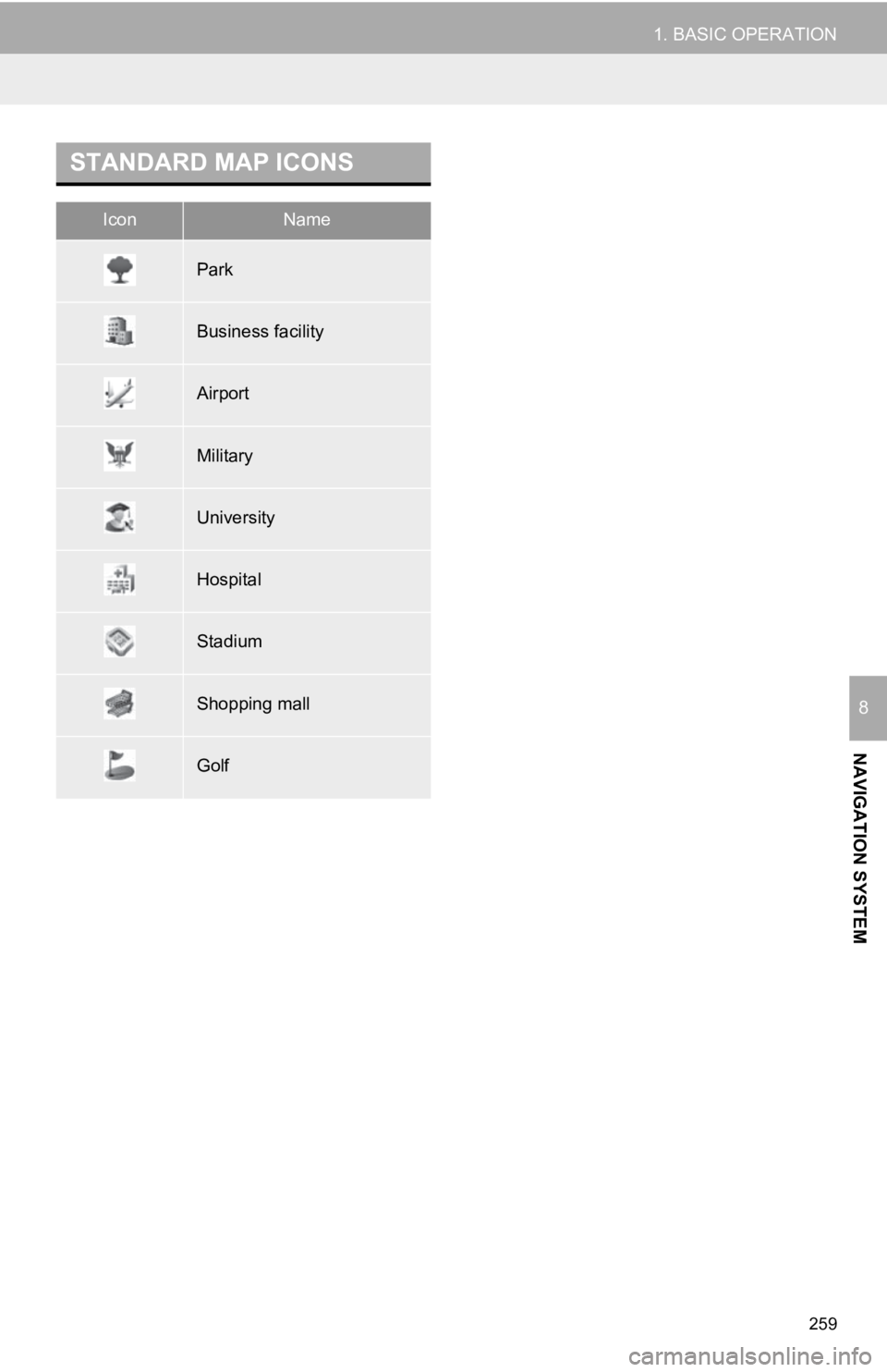
STANDARD MAP ICONS
IconName
Park
Business facility
Airport
Military
University
Hospital
Stadium
Shopping mall
Golf
Page 261 of 350
261
1. BASIC OPERATION
NAVIGATION SYSTEM
8
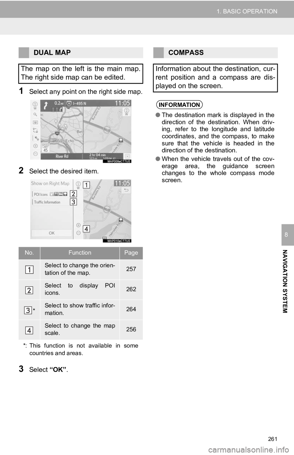
1Select any point on the right side map.
2Select the desired item.
3Select “OK”.
DUAL MAP
The map on the left is the main map.
The right side map can be edited.
No.FunctionPage
Select to change the orien-
tation of the map.257
Select to display POI
icons.262
*Select to show traffic infor-
mation. 264
Select to change the map
scale.256
*: This function is not available in some countries and areas.
COMPASS
Information about the destination, cur-
rent position and a compass are dis-
played on the screen.
INFORMATION
● The destination mark is displayed in the
direction of the destination. When driv-
ing, refer to the longitude and latitude
coordinates, and the compass, to make
sure that the vehicle is headed in the
direction of the destination.
● When the vehicle travels out of the cov-
erage area, the guidance screen
changes to the whole compass mode
screen.
Page 263 of 350
263
1. BASIC OPERATION
NAVIGATION SYSTEM
8
1Select on the map screen.
(P.254)
2Select “Route Trace”.
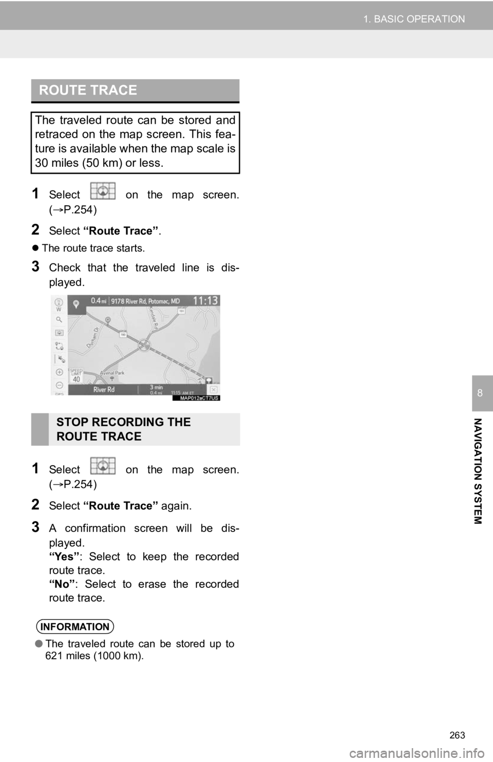
The route trace starts.
3Check that the traveled line is dis-
played.
1Select on the map screen.
(P.254)
2Select “Route Trace” again.
3A confirmation screen will be dis-
played.
“Yes”: Select to keep the recorded
route trace.
“No” : Select to erase the recorded
route trace.
ROUTE TRACE
The traveled route can be stored and
retraced on the map screen. This fea-
ture is available when the map scale is
30 miles (50 km) or less.
STOP RECORDING THE
ROUTE TRACE
INFORMATION
● The traveled route can be stored up to
621 miles (1000 km).
Page 265 of 350
265
1. BASIC OPERATION
NAVIGATION SYSTEM
8
1Display the traffic incidents screen.
(P.264)
2Select “Traffic Events on Current
Road”, “Traffic Events on Current
Route” or “Traffic Events Nearby” .
3Select the desired traffic information.
When “Traffic Events Nearby” is se-
lected, depending on whether the traffic
flow information is enabled/disabled, the
following will be displayed:
When enabled: Traffic event and conges-
tion information
When disabled: Traffic event information
only
4Check that the traffic information is dis-
played.
“Detail” : Select to display detailed traffic
information.
1Display the traffic incidents screen.
(P.264)
2Select “Predictive Traffic Map” .
3Scroll the map to the desired point and
set the time of predictive traffic infor-
mation.
The time of the predictive traffic informa-
tion can be changed in 15-minute intervals
up to +45 minutes.
“<”: Moves the time forward 15 minutes.
“
>”: Moves the time back 15 minutes.
DISPLAYING TRAFFIC
INFORMATION
A list of current traffic information can
be displayed along with information on
the location of each incident.DISPLAYING PREDICTIVE
TRAFFIC INFORMATION
A map with predictive traffic data can
be displayed.