relay TOYOTA CAMRY V20 1986 Service Information
[x] Cancel search | Manufacturer: TOYOTA, Model Year: 1986, Model line: CAMRY V20, Model: TOYOTA CAMRY V20 1986Pages: 2389, PDF Size: 84.44 MB
Page 2260 of 2389
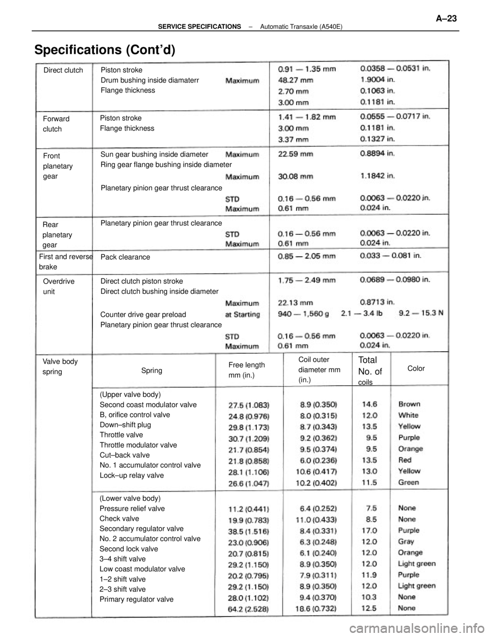
(Lower valve body)
Pressure relief valve
Check valve
Secondary regulator valve
No. 2 accumulator control valve
Second lock valve
3±4 shift valve
Low coast modulator valve
1±2 shift valve
2±3 shift valve
Primary regulator valve(Upper valve body)
Second coast modulator valve
B, orifice control valve
Down±shift plug
Throttle valve
Throttle modulator valve
Cut±back vaIve
No. 1 accumulator control valve
Lock±up relay valvePiston stroke
Drum bushing inside diamaterr
Flange thickness
Sun gear bushing inside diameter
Ring gear flange bushing inside diameter
Counter drive gear preload
Planetary pinion gear thrust clearanceDirect clutch piston stroke
Direct clutch bushing inside diameter Planetary pinion gear thrust clearancePlanetary pinion gear thrust clearance
Specifications (Cont'd)
Piston stroke
Flange thickness
Coil outer
diameter mm
(in.) Rear
planetary
gearFront
planetary
gear Forward
clutch
First and reverse
brake
Free length
mm (in.) Valve body
springOverdrive
unit
Total
No. of
coils Pack clearance Direct clutch
SpringColor
± SERVICE SPECIFICATIONSAutomatic Transaxle (A540E)A±23
Page 2261 of 2389
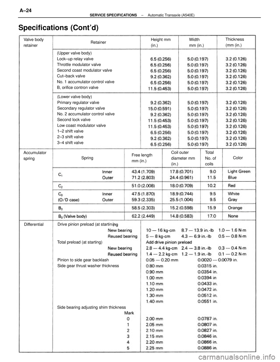
(Lower valve body)
Primary regulator valve
Secondary regulator valve
No. 2 accumulator control valve
Second lock valve
Low coast modulator valve
1±2 shift valve
2±3 shift valve
3±4 shift valve (Upper valve body)
Lock±up relay valve
Throttle modulator valve
Second coast modulator valve
Cut±back valve
No. 1 accumulator control valve
B, orifice contron valve
Pinion to side gear backlash
Side gear thrust washer thickness
Specifications (Cont'd)
Side bearing adjusting shim thicknessDrive pinion preload (at startin )
Total preload (at starting)Coil outer
diameter mm
(in.) Accumulator
springFree length
mm (in.) Valve body
retainerThickness
(mm (in.)
Total
No. of
coils Width
mm (in.) Height mm
(in.)
DifferentialRetainer
SpringColor
± SERVICE SPECIFICATIONSAutomatic Transaxle (A540E)A±24
Page 2310 of 2389
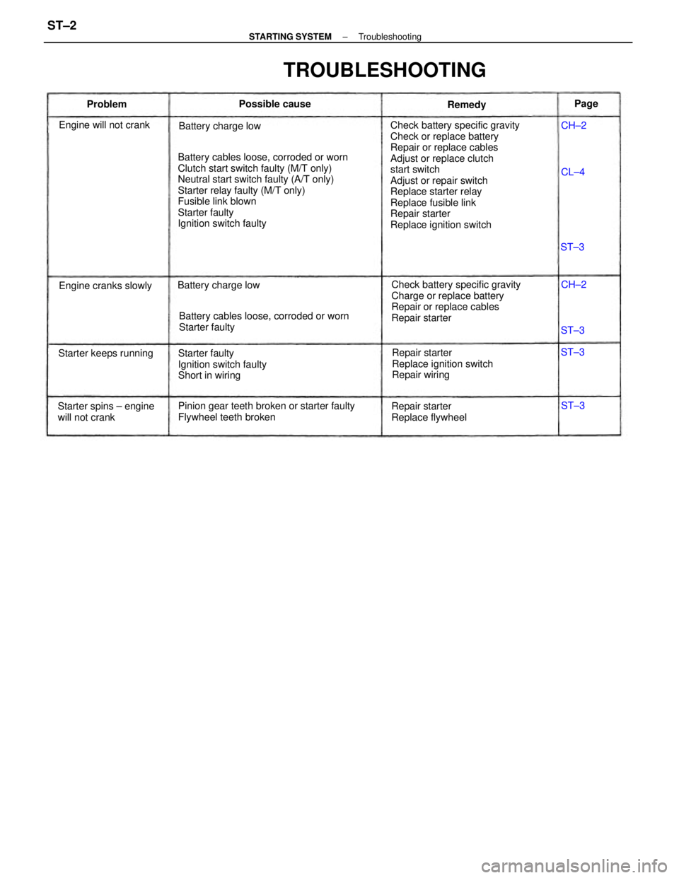
Check battery specific gravity
Check or replace battery
Repair or replace cables
Adjust or replace clutch
start switch
Adjust or repair switch
Replace starter relay
Replace fusible link
Repair starter
Replace ignition switch Battery cables loose, corroded or worn
Clutch start switch faulty (M/T only)
Neutral start switch faulty (A/T only)
Starter relay faulty (M/T only)
Fusible link blown
Starter faulty
Ignition switch faulty
Check battery specific gravity
Charge or replace battery
Repair or replace cables
Repair starter
Pinion gear teeth broken or starter faulty
Flywheel teeth brokenBattery cables loose, corroded or worn
Starter faulty
Repair starter
Replace ignition switch
Repair wiring Starter faulty
Ignition switch faulty
Short in wiring
TROUBLESHOOTING
Starter spins ± engine
will not crankRepair starter
Replace flywheel Engine will not crank
Starter keeps runningBattery charge low
Engine cranks slowlyBattery charge lowPossible cause
Remedy ProblemPage
CH±2
CH±2
ST±3 ST±3
ST±3
ST±3 CL±4
± STARTING SYSTEMTroubleshootingST±2
Page 2324 of 2389
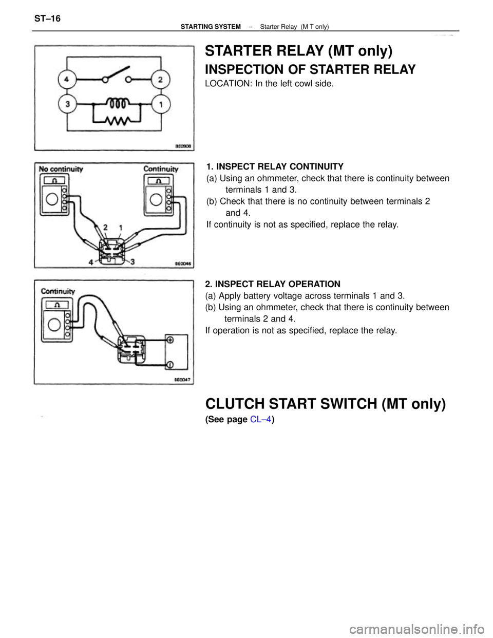
1. INSPECT RELAY CONTINUITY
(a) Using an ohmmeter, check that there is continuity between
terminals 1 and 3.
(b) Check that there is no continuity between terminals 2
and 4.
If continuity is not as specified, replace the relay.
2. INSPECT RELAY OPERATION
(a) Apply battery voltage across terminals 1 and 3.
(b) Using an ohmmeter, check that there is continuity between
terminals 2 and 4.
If operation is not as specified, replace the relay.
STARTER RELAY (MT only)
INSPECTION OF STARTER RELAY
LOCATION: In the left cowl side.
CLUTCH START SWITCH (MT only)
(See page CL±4)
± STARTING SYSTEMStarter Relay (M T only)ST±16
Page 2325 of 2389
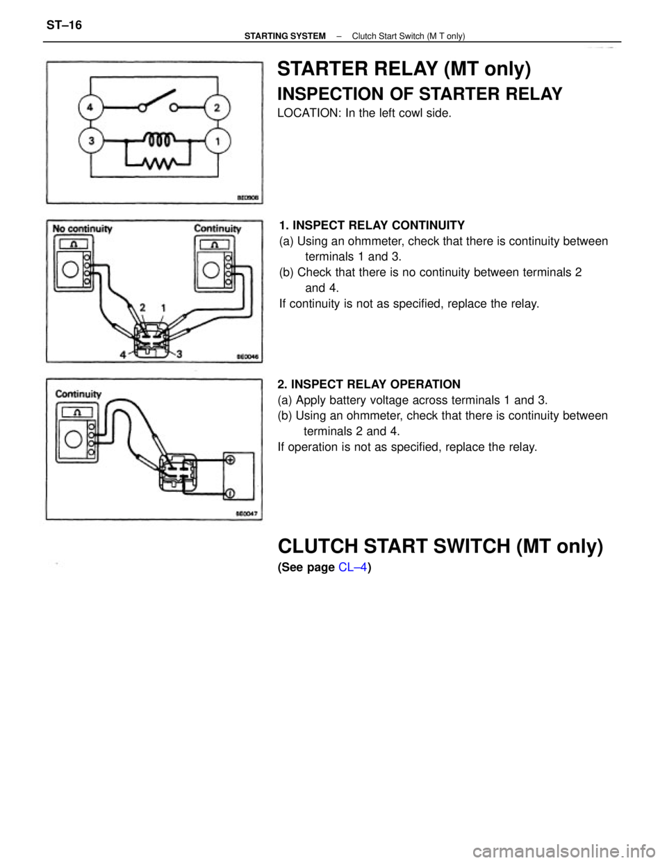
1. INSPECT RELAY CONTINUITY
(a) Using an ohmmeter, check that there is continuity between
terminals 1 and 3.
(b) Check that there is no continuity between terminals 2
and 4.
If continuity is not as specified, replace the relay.
2. INSPECT RELAY OPERATION
(a) Apply battery voltage across terminals 1 and 3.
(b) Using an ohmmeter, check that there is continuity between
terminals 2 and 4.
If operation is not as specified, replace the relay.
STARTER RELAY (MT only)
INSPECTION OF STARTER RELAY
LOCATION: In the left cowl side.
CLUTCH START SWITCH (MT only)
(See page CL±4)
± STARTING SYSTEMClutch Start Switch (M T only)ST±16